
![]()
Using Arduino with PIC32 and ATtiny Atmel Chips
Transitioning from standard to custom Arduino hardware can save space and money. Custom boards can add new capabilities to projects through increased speed, memory, and pins, as well as new features. This chapter will look at chips and boards on a spectrum from the power and complexity of the Leonardo to the inexpensive simplicity of the ATtiny. It will examine the unique capabilities of the chipKIT environment based on the Microchip’s PIC32 series micro-controller. Then the chapter will demonstrate some unique libraries and features of the chipKIT environment, including support for scheduling timers, which make object detection with Infra-Red (IR) simple. As an example using the Atmel ATtiny environment, you will program a secret knock to operate a servo motor, which will open and close a small wooden box.
Arduino and Nonstandard Environments
Arduino is both a physical specification and a software abstraction layer. Since the Arduino API functions so effectively, it has been ported to many different platforms and microcontrollers. chipKIT is one of the earliest of these platforms and the first one that supported compiling code for both itself and Arduino. Multiplatform Arduino means that that the Arduino environment can compile code for multiple families of different chips. The multiplatform IDE (MPIDE) can compile Arduino code for Atmel chips and the multiple-platform PIC32.
There is now a broad choice of Arduino-compatible options, including faster and slower chips, with a range of available numbers of pins, and a variety of other features. This spectrum of complexity results in a spectrum of price points. For example, the Arduino Due has an ARM Cortex 3 chip that enhances Arduino performance and has capabilities at similar levels to that of the chipKIT.
These high-performance options work best for some purposes. For example, such an option would be ideal if you were trying to create a project that causes 26 small boxes to blink Morse code, listen with piezos, or unlock boxes. You could customize the projects to include a low-cost chip that has a custom circuit board to make the project affordable. Using these additional environments through the Arduino API allows you to use a high-end prototype. With the Arduino advantage of quick code prototyping, you can make a smooth transition for porting a project from a standard Arduino Uno and put the project on a smaller and less expensive ATtiny family of chips.
Lastly, I will be showing how to program smaller chips like the ATtiny85 from a standard Arduino. You will examine how to make the Arduino a programmer for the ATtiny85 chip—a technique that can be used for the entire ATtiny family, and for many other chips. You will also use the MPIDE to create a PIC32 Arduino-inspired project.
chipKIT is an Arduino-derived variation that uses significantly faster hardware and has much more memory. In this section, you will explore bigger, high-end options. The reference boards for the chipKIT environments are the Digilent chipKIT Uno32 (shown in Figure 9-1) and the chipKIT Max32. The platform has been around long enough that there are chipKIT-compatible boards, such as the chipKIT FubarinoSD and chipKIT Fubarino Mini. These boards all fall in the same price range as the Arduino Uno and the Arduino Mega, but they have significantly improved performance. The Arduino Due board is comparable in speed.

Figure 9-1. Chipkit Reference Board the Uno32 by Digilent Inc
The chipKIT home page is at http://chipkit.net, and the documentation for the project is located at http://chipkit.net/category/chipkit-projects. Support and discussion of the project is at the chipKIT forum, at http://chipkit.org/forum. Lastly, the MPIDE source code and bootloader are located at https://github.com/chipKIT32/chipKIT32-MAX. Table 9-1 gives a comparison of the two boards.
Table 9-1. Comparison of the Built-In Features of the chipKIT Max32 and the Arduino Mega
| Features | chipKIT Max32 | Arduino Mega |
|---|---|---|
| CPU performance | 80 MHz | 16 MHz |
| Core | 32 bit | 8 bit |
| Flash memory | 512 KB | 256 KB |
| SRAM/program memory | 128 KB | 8 KB |
| Digital I/O | 83/5 PWM | 54/14 PWM |
| Analog I/O | 16 | 16 |
| RTCC | Yes | No |
| Ethernet | Yes, with add-on shield | No |
| USB | USB 2.0 FS, device/host, OTG | |
| CAN controllers | 2 | 0 |
| Timers | 16/32 bit | 8/16 bit |
| Comparators | 2 | 1 |
| I2C | 5 | 1 |
| SPI | 2 | 1 |
| UART | 6, with IrDA | 4 |
Digilent has created additional libraries to take advantage of the unique hardware. In addition to the standard Arduino SPI, there are some improved SPI libraries, including Digilent SPI (DSPI) and Open Source Serial Peripheral Interface hardware with SPI support. Software SPI (SoftSPI) is a software implementation of SPI that allows any pin to be used for SPI communication. Software Pulse Width Modulation Servo (SoftPWMServo) ensures that every pin can be used. It also has improved timer support with the Core Timer Service, and a Task Management service. I will demo those features later in this section.
![]() Note The editor is a derivation of the ArduinoThis ChipKit Max32 board in Table 9-1 has many features which put it on the same playing field as the Arduino Due. Additional features like Ethernet, and Car Area Network(CAN) Bus allow for less expensive shields that bring out these features to pins on Ethernet, or CAN Bus shield. More chip details can be found at http://www.chipkit.org/wiki/index.php?title=ChipKIT_Max32.
Note The editor is a derivation of the ArduinoThis ChipKit Max32 board in Table 9-1 has many features which put it on the same playing field as the Arduino Due. Additional features like Ethernet, and Car Area Network(CAN) Bus allow for less expensive shields that bring out these features to pins on Ethernet, or CAN Bus shield. More chip details can be found at http://www.chipkit.org/wiki/index.php?title=ChipKIT_Max32.
Another thing in common with the Arduino Due is power issues. There are many pins on the ChipKit Max32 that are 5v tolerant, but not all are. Here are some caveats when powering pins:
- The PIC32 MCUs on these boards have an operational voltage of 3.3V. The ChipKit MAX32, UNO32, and u32 boards are 5V tolerant, meaning you can input 5V to get a digital or analog reading without burning out the chip. However, these chips only output a maximum of 3.3V. Some 5V components may not recognize 3.3V.
- The readings will be made by default in the range of 0–3.3V instead of 0–5V. So, you will have to change the values in your own code or libraries in order to obtain the correct range. This may include using a logic level converter for a 5V device. However, many components are already 3.3V compatible, so, for example, you will not need a logic level converter for chipKIT or Arduino Due boards. The Arduino revision 3 shield specification includes an IOREF pin. If your code checks this pin value, you can enable the appropriate level converter for your board.
- For I2C, there needs to be external pull-up resistors. The PIC32 does not have internal pull-up resistors for every digital pin, so it is best to not use them. You can also design shields or breadboard projects by including the needed pull-up resistors, typically 2–2.7kΩ. This helps make a shield or project compatible with the Arduino Leonardo, which also does not have pull-up resistors on the I2C pins.
![]() Note The editor is a derivation of the Arduino IDE, and it acts and performs the same as the Arduino 1.0 editor. However, at the time of writing, it supports the Arduino 0023 core.
Note The editor is a derivation of the Arduino IDE, and it acts and performs the same as the Arduino 1.0 editor. However, at the time of writing, it supports the Arduino 0023 core.
Digilent Incorporated has created additional libraries to take advantage of the unique hardware. In addition to the standard Arduino SPI, there is Digilent Serial Peripheral Interface (DSPI) for hardware based SPI support. Additionally, there is an official Software SPI (SoftSPI) is a software implementation of SPI that allows any pin to be used for SPI communication. It is common when using shield to have a conflict with a pin that is already using SPI. Being able to use software create a new SPI pin gets around that conflict.
Software Pulse Width Modulation Servo (SoftPWMServo) ensures that every pin can be used. The SoftPWMServo library allows for any pin on a ChipKit board to support servos.
It also has improved timer support with the Core Timer Service, and a Task Management service. The Core Timer Service will let you work on timing issues with micro second resolution. Whereas the Task Management Service will let you work at millisecond resolution. We will use the Task Management Service to do object detection with in timed intervals that will not interfere with your code in the main loop. Also, it will not require polling the sensors in your loop code.
Example: Object Detection using the Task Manager service
In this example, you will use one chipKIT Uno32, two IR LEDs, and one IR sensor. The example uses the ChipKit Task Manager to register two tasks that blink the IR LEDs at specified intervals. Figure 9-2 shows the project breadboard layout. The sensors are connected to pins 5, and 6. The IR sensor is connected to pin 2 which is an interrupt pin. This will allow the IR sensor to immediately trigger upon the detection of IR.

Figure 9-2. Uno32 IR LED sensor and emmiter wiring example
The code in Listing 9-1 is loaded using MPIDE. The chipKIT Uno32 is both a listener and broadcaster. It blinks and receives information about whether or not reflections from the IR LEDs. The code is non-blocking, so you can simultaneously perform other actions while it is working. It is possible to operate a servo and respond to objects detected in the front, left, or right of the sensor.
Listing 9-1. IR Object Detection Using the Task Manager Code Example
/*
* Object Detection with the Core Task Manager Service
 * Determine with one sensor which where an object is
 * 2 - 4 IR LEDs
 * 1 IR Sensor
 */

//PIN_INT1 for the ChipKit UNO32 is Pin 2
#define pinInt PIN_INT1

#define SENSOR1_PIN 2
#define EMITTER1_PIN 5
#define EMITTER2_PIN 6
#define BEATS 6
In Listing 9-2 the interrupt pin is defined as PIN_INT1. This is a generic way to refer to interrupt 1. Depending on what kind of ChipKit you use these can map to different pins on the hardware. For a ChipKit Uno32 these map to pin 2. If you wanted to use a different interrupt you could use:
Listing 9-2. define hardware values
PIN_INT0        38
PIN_INT1        2
PIN_INT2        7
PIN_INT3        8
PIN_INT4        35
When ever you switch to a different board you will want to double check which pins correspond to the correct interrupt.
int emmiter1_id;
int emmiter2_id;

unsigned long blink1_var;
unsigned long blink2_var;
In Listing 9-3 the the required ChipKit Task Manager variables are defined emmiter1_id, and emmiter2_id are the task identifier variable that are used to register the task. The blink1_var, and blink2_var are the the data variables that are passed into the task function and represent the current time information.
Listing 9-3. ChipKit Task Manager Library require variables
volatile boolean emitter1State = LOW;
volatile boolean emitter2State = LOW;
volatile boolean prevEmitter1State = LOW;
volatile boolean prevEmitter2State = LOW;

volatile boolean detected = LOW;
volatile boolean e1detected = LOW;
volatile boolean e2detected = LOW;

volatile unsigned long emit1Count = 0;
volatile unsigned long emit2Count = 0;
volatile unsigned long detectCount = 0;
The meta data about the task are defined. This includes detection count, current emitter status, previous emitter status, and which emitter was detected. These values will be adjusted in the task manger functions, and the when the detection interrupt is triggered.
Listing 9-4. Emmiter data defined and initialized with default values
volatile int phaseA = 0;
volatile int phaseB = 0;
volatile int prevPhaseA = -1;
volatile int prevPhaseB = -1;
volatile int measureA = 0;
volatile int measureB = 0;
volatile int prevMeasureA = -1;
volatile int prevMeasureB = -1;
A measure is defined as the basic container of a set number of intervals that can be thought of as beats per measure. As each of these beats is stepped through the phase of the measure is updated. The default configuration is 6 beats per measure. Every time a task is activated it increases the phase until it reaches the end of the measure and the measure and phases start over again.
Listing 9-5. The measeure and the phase of the measure are defined and initialized
//Prototypes
void blink_emitter1(int id, void * tptr);
void blink_emitter2(int id, void * tptr);
void readIRSensor();
void blink(int);
In Listing 9-6 the prototypes are required because the functions are defined after the loop code. So the prototypes have to be listed.
Listing 9-6. Prototypes of the functions used by the interrupt system, and the task manger code.
void setup() {
  Serial.begin(115200);
  delay(2000);
  // initialize the digital pin as an output.
  // Pin PIN_LED1 has an LED connected on most Arduino boards:
  pinMode(pinInt, INPUT);
  //debugging LED, shows when pulse found
  pinMode(PIN_LED1, OUTPUT);
  digitalWrite(PIN_LED1, HIGH);
  pinMode(SENSOR1_PIN, INPUT);
  pinMode(EMITTER1_PIN, OUTPUT);
  pinMode(EMITTER2_PIN, OUTPUT);

  digitalWrite(EMITTER1_PIN, LOW);
  digitalWrite(EMITTER2_PIN, LOW);
  //blink before timers and interrups
  blinkAll(6);
In Listing 9-7 the code uses the defined hardware and configure it corectly for the starting state of the project. This includes a diagnostic called blinkAll. One you see all the LEDs blinking, the hardware is configured correctly and is ready to detect the IR pulses.
Listing 9-7. Configuration code the hardware.
  attachInterrupt(SENSOR1_PIN, readIRSensor, RISING);
  emmiter1_id = createTask(blink_emitter1, 13, TASK_ENABLE, &blink1_var);
  emmiter2_id = createTask(blink_emitter2, 13, TASK_ENABLE, &blink2_var);

}
In Listing 9-8 the code attaches the interrupt to the pin it is checking to see if it changes. When the pin is in a rising state, meaning that it goes from a LOW state to a HIGH state perform a callback to the readIRSensor function. This guarantees that as soon as the sensor detects an IR pulse it triggers immediately without the need to constantly check in your loop code a pulse came in.
The next section of code in Listing 9-8 uses the createTask function to set up the task of blinking led emmiter1. The task id is stored in emmiter1_id. Any time a manipulation of the task is required this id can be used to reference the task. In the function the first portion is the callback function blink_emmiter1. Blink_emmiter1 is called in a 13 millisecond interval. TASK_ENABLE forces the task start right away, and the task data is stored in blink1_var. The same logic applies for the second emitter. At this point the device is sensing and blinking with no code in the main loop used to control these events. This way your code is always remains specific to your goal, and only needs to respond to a detection of an IR pulse.
Listing 9-8. Create and activate the interrupt, and the tasks that control the IR leds.
void loop() {
  digitalWrite(PIN_LED1, LOW);

  if (detected) {
    Serial.print("{ "IRDetect": ");
    Serial.print(detectCount);
    Serial.print(" ,"measureA": ");
    Serial.print(measureA);
    Serial.print(" ,"measureB": ");
    Serial.print(measureB);
    Serial.print(" ,"phaseA": ");
    Serial.print(phaseA);
    Serial.print(" ,"phaseB": ");
    Serial.print(phaseB);
    Serial.print(" ,"Emmit1": ");
    Serial.print((int)emitter1State);
    Serial.print(" ,"prevEmmit1": ");
    Serial.print((int)prevEmitter1State);
    Serial.print(" ,"count": ");
    Serial.print(emit1Count);
    Serial.print(" ,"Emmit2": ");
    Serial.print((int)emitter2State);
    Serial.print(" ,"prevEmmit2": ");
    Serial.print((int)prevEmitter2State);
    Serial.print(" ,"count": ");
    Serial.print(emit2Count);
The current statue of the system is reported on by using the serial output to show the status of the system in JSON format.
Listing 9-9. The main loop reports on the status of the system in a JSON format via serial.
    if(emitter1State) {
      prevEmitter1State = emitter1State;
      Serial.print(" ,"Obj": "Right"");
    }
    if (prevMeasureA == measureA) {
      if (e1detected && e2detected)
      {
        Serial.print(" ,"Obj": "Front"");
      }
    }
   if(emitter2State) {
      prevEmitter2State = emitter2State;
      Serial.print(" ,"Obj": "Left"");
    }
    Serial.println("}");
    prevMeasureA = measureA;
    prevMeasureB = measureB;
    prevPhaseA = phaseA;
    detected = false;
  }

}
Listing 9-10 shows the detection logic. If only emitter1 is detected in a measure there is an object on the left. If only emitter2 is detected in a measure then an object on the right is detected. If in the measure both emitter1, and emmiter2 are detected there is an object in front of the device.
Listing 9-10. The detection logic is defined by what is detected in a single measure.
void readIRSensor() {
  digitalWrite(PIN_LED1, HIGH);
  if(emitter1State) {
    emit1Count++;
    detectCount++;
    detected = true;
    e1detected = true;
  }
  else if (emitter2State) {
    emit2Count++;++;
    detectCount++;
    detected = true;
    e2detected = true;
  }
}
Listing 9-11. readIRsensor function is defined.
void blink_emitter1(int id, void * tptr) {
  if(phaseA >= BEATS) {
    phaseA = 0;
    measureA++;
    e1detected = false;
  }

  if (phaseA== 1) {
    emitter1State = true;
    phaseA++;
    digitalWrite(EMITTER1_PIN, emitter1State);
  }
  else  {
    emitter1State = false;
    phaseA++;
    digitalWrite(EMITTER1_PIN, emitter1State);

  }
}

void blink_emitter2(int id, void * tptr) {
  if(phaseB >= BEATS) {
    phaseB = 0;
    measureB++;
    e2detected = false;
  }
  if (phaseB == 3) {
    emitter2State = true;
    phaseB++;
    digitalWrite(EMITTER2_PIN, emitter2State);
  }
  else
  {
    emitter2State = false;
    phaseB++;
    digitalWrite(EMITTER2_PIN, emitter2State);
  }
}
Listing 9-12. Blink_emitter1 and blink_emitter2 task are defined.
void blinkAll(int loops)
{
  for (int ii = 0; ii < loops; ii++)
  {
    digitalWrite(PIN_LED1, HIGH);
    digitalWrite(EMITTER1_PIN, HIGH);
    digitalWrite(EMITTER2_PIN, HIGH);
    delay(250);
    digitalWrite(PIN_LED1, LOW);
    digitalWrite(EMITTER1_PIN, LOW);
    digitalWrite(EMITTER2_PIN, LOW);
    delay(250);
  }
}
Blink all is used as diagnostic function
The code sends timed infrared pulses that are then detected by an IR sensor, so you can debug it and determine which port is sending data. Connect the chipKIT Uno32 and open the serial monitor in the MPIDE. Then power up or connect the USB to the FubarinoSD, and it will start transmitting. You should now see frequency counts per second in your serial MPIDE monitor, and you can perform line-of-sight infrared object detection or detect remote beacon.
In this project the code is depends very little on what occurs in the loop. The only loop code that is used is to make a decision about where the object is that was detected. Knowing the object position can cause your robot or device to respond in several different ways including avoidance or point towards it in case you were choosing to move a camera to look at what was detected. By using these advanced features of interrupts with the Core Task Manager, service complicated tasks become much easier.
Arduino Support for the ATtiny Family
There are two main ATtiny cores for Arduino. One is maintained by David Mellis at the Hi-Low Tech MIT web site (http://hlt.media.mit.edu/?p=1695), and the other is a Google Code project called ATtiny core, at http://code.google.com/p/arduino-tiny/. This chapter will use the ATtiny core project from Google Code, as it includes support for a wider array of chips, features, and pins.
The ATtiny chips arrive from the factory with fuses set for less than 1 MHz, so you have to decide at what speed you want your chip to run. The ATtiny85 runs at 1 MHz, but it can be configured to run at 8 MHz, 16 MHz internally, or 20 MHz with a crystal or oscillator. The first step in programming these chips is to burn the fuse configuration to support the clock that you will use.
![]() Note If you don’t burn the bootloader, or if you set it to the wrong speed, your chip will not perform at the expected speed.
Note If you don’t burn the bootloader, or if you set it to the wrong speed, your chip will not perform at the expected speed.
You can do this in the Arduino IDE by selecting the chip and the speed from the Tools menu, as shown in Figure 9-3.
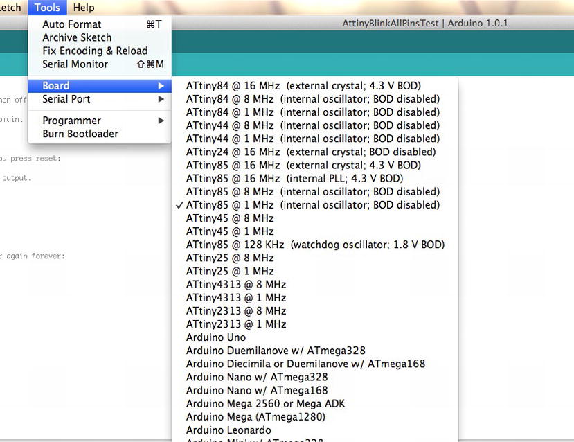
Figure 9-3. The Board option on the Tools menu
Next, select the Burn Bootloader option, as shown in Figure 9-4. This will trigger Avrdude to program the correct options in your chip.

Figure 9-4. The Burn Bootloader option
While the Atmel family of chips is compatible with Arduino, its pin-numbering scheme is different. Let’s look at the features and specifications of the ATtiny chips in Tables 9-2, 9-3, and 9-4, paying particular attention to the pin numbering, as diagrammed in Figures 9-5, 9-6, and 9-7.
The Atmel family consists of the following chips:
- ATtiny 85, 45, and 25
- ATtiny 84, 44, and 24
- ATtiny 4313 and 2313
Table 9-2 shows the chip specifications for the ATtiny 85, 45, and 25.
Table 9-2. Chip Specifications for the Arduino ATtiny 85/45/25
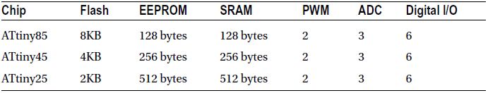

Figure 9-5. Pin layout of the ATtiny 85/45/25
Pin 7 supports I2C, and pin 5 supports SCL and SDA, as shown in Figure 9-3. This support is maintained through the TinyWire library. The code can be found at http://arduino.cc/playground/Code/USIi2c.
Table 9-3 shows the chip specifications for the ATtiny 84, 44, and 24.
Table 9-3. Chip Specifications for the Arduino ATtiny 84/44/24


Figure 9-6. Pin layout of the ATtiny 84/44/24
I2C is supported on pin 7, and SDA and SCL are supported on pin 9, as shown in Figure 9-4.
Table 9-4 shows the chip specifications for the ATtiny 4313 and 2313.
Table 9-4. Chip Specifications for the ATtiny 4313 and 2313


Figure 9-7. Pin layout of the ATtiny 4313 and 2313
These chips do not have a standard serial interface, so the normal Arduino bootloader does not work with these chips. You must manually set the chip configuration in one step, and then you can program the chip using an in-system programmer. The protocol is SPI.
Each of these chips has the following:
- MISO
- MOSI
- Vcc
- GND
- SCK
- RESET
Using the Arduino as an ISP Programmer
An in-system programmer(ISP) is a device that can program other chips. There are several system programmers available. I recommend the Adafruit USBTinyISP, which you can download at https://www.adafruit.com/products/46. In this case, as shown in Figure 9-8, you want to use the Arduino as an ISP programmer, which allows you to wire it directly, and to create a custom PCB, or to make a shield for quick programming.

Figure 9-8. The Arduino Uno as an ISP programmer
The ATtiny in the example is the ATtiny85. Other ATtiny chips can be programmed the same way as long as the correct ISP pins are mapped. The example in Figure 9-6 also shows a corresponding circuit board that you can create.
Since an Arduino resets when connected via a serial port, you will need to disable the reset pin in order to avoid a reset when programming. This can be done in a couple of way—you can either use a 10μF capacitor from the reset pin to the ground or a 124Ω resistor to pull reset high to the 5V pin.
Analog pins are numbered from 1,2 and 3. They correspond to the pins 7, 3, and 2 on the chip, but are referenced in this way: ADC1 is 1, ADC 2 is 2, and ADC 3 is 3. Since they are already properly initialized, do not set the pin mode for analog pins. All the digital pins can be referenced via their pin number on the data sheet.
![]() Note It is possible to program an ATtiny that is configured for 1 MHz, as 8 MHz will cause the delay functions to be extra slow.
Note It is possible to program an ATtiny that is configured for 1 MHz, as 8 MHz will cause the delay functions to be extra slow.
It is also important to note that internal analog reference is usually 1.1, but it is possible to set it to other values too; however, you must not apply an external voltage to the AREF pin, or else you will short out the op amp in the ADC.
Given these features, it is possible to program the ATtiny using an Arduino by configuring an Arduino Uno or another board with the Arduino ISP sketch and wiring the boards to each other, which I will demonstrate in the following example.
In this example, you will use a secret-knock example to open a small box with a servo. The idea is to detect a knock and then trigger a servo to open the box. Then you can then use a double-knock to close the box. The box remains closed until the secret knock is identified. This technique has been used to open doors and boxes and to trigger events based on a knock code. I used them in my Morse’s Secret Box project, where tapping Morse code opened the box. The laser-cut designs for these boxes can be found online at http://github.com/ricklon/morsessecret. A custom circuit board for the project, called the ATtiny Servo, is available as well, at https://github.com/ricklon/attinyservo.
This project is typically done with a larger chip or a standard Arduino Uno. However if you were to make 20, 30, or even a thousand of these boxes the cost and complexity would be very high. This makes it impractical to sell a project for a profit, or efficiently reduce the complexity of project. It is a good idea to prototype on an Arduino Uno which on average costs $35.00 per unit. In this case, though, you want to use the ATtiny85, which costs around $1.29, or approximately $0.75 in quantities of 25.
The options for this chip are somewhat limited, so if Servo.h is unavailable, there are other servo options available. However, because there is only one timer on the chip, there is a conflict with the Arduino standard Servo Library. Other servo options are available, but the very basic option is to operate the servo manually by programming the chip to send the servo pulse commands. This solution works well, and is modeled by this project.
This chapter introduces a project that uses a knock sensor to tap a secret code. LEDs are used to show a knock occurred, and was detected. When the correct code is sensed a command is sent to move a servo to open a box lid. An ATtiny85 is used because it has a small form factor, and the additional electronics can fit in extremely small spaces.
What the Device Does
When you program a knock pattern into the device, the system listens for the knock, and the servo is triggered to open the box. Additionally, there is a programming mode where you can set the knock and use some LEDs for feedback on the programming process. This project transforms the code from just a stand alone sketch to a library that can be used in many projects.
Bill of Materials
For this project, you will need the following:
- Servo
- Piezo
- Two LEDs
- One button
- Two resistors (220kΩ)
- One 6MΩ resistor
The project is small enough to be a simple do-it-yourself PCB or a breadboard, as in Figure 9-9; it can also use dead bug–style wiring.
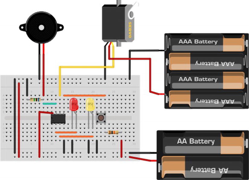
Figure 9-9. Circuit diagram of the knock box
The Arduino sketch is called KnockUnlock.ino, and includes a servo.h library and a SecretKnock.h library. The servo.h library simply configures the servo to move at a specific pulse for a specified number of milliseconds. The SecretKnock.h library defines an object, which allows for the configuration of an initial secret knock and the appropriate feedback pins to reprogram the knock sequence.
Listing 9-13 is the main sketch.
Listing 9-13. Main Sketch of Secret Knock Box
#include "SecretKnock.h"
#define SERVO_PIN 1

int initKnocks[MAX_KNOCKS]= { 50, 25, 25, 50, 100, 50, 50, 0, 0, 0, 0, 0, 0, 0, 0, 0, 0, 0, 0, 0};

SecretKnock sKnock;

void setup() {

sKnock.begin(initKnocks);

}

void loop() {

  sKnock.checkKnock();

}
The current configuration detects a “shave and a haircut, two bits” type of knock. It sounds like “dah, dit, dit, dah, dit, pause, dit, dit”, and can be visualized like “_.._. ..” You can change this to any knock combination by defining the pauses in the antiknocks. The pause ratio is used to determine if there are any matching knocks.
Most of the work is completed in the SecretKnock object. First, the pin configurations include the servo—the green LED is pin 3, the red LED is pin 4, the piezo’s knock sensor is analog pin 1, the program button is pin 0, and the servo pin is #define SERVO_PIN 1, which is digital pin 1.
Then the secret knock properties are defined, as in Listing 9-14.
Listing 9-14. Definging the Properties of the Secret Knock
threshold = 500;           // Minimum signal from the piezo to register as a knock
rejectValue = 25;          // If an individual knock is off by this percentage of a knock we don't unlock.
averageRejectValue = 15;   // If the average timing of the knocks is off by this percent we don't unlock.
knockFadeTime = 200;       // milliseconds we allow a knock to fade before we listen for another one. (Debounce timer.)
lockTurnTime = 650;        // milliseconds that we run the motor to get it to go a half turn.
lockMotor = 2;
knockComplete = 1200;      // Longest time to wait for a knock before we assume that it's finished.
Once this is complete, the code is ready to perform checkKnock() in the main loop() function. Once the first knock is detected, it will seek to match a knock pattern.
The enclosure can be any kind of box that you want; you use the servo as a lock that opens when the secret knock triggers the move-servo code.
You can program the code into the ATtiny85 using the technique demonstrated in Listing 9-13, but be sure to disconnect the servo.
The servo code, as shown in Listing 9-13, is simplified to manually pulse the servo to make it move. This technique requires the chip to keep pulsing for the length of time it takes to move the servo. The result is that only one servo at a time can be active. Even if you were to configure multiple servos, you could only move one at a time.
The key to reading the knock sensor is inside of the checkServo() function. This is analogRead(knockSensor), which checks if the piezo is greater than the trigger threshold. If so, the code will start listening for a knock pattern.
A knock pattern is recognized by the ratio of pauses within a certain tolerance. The code that makes that comparison appears in Listing 9-15.
Listing 9-15. The Code That Identifies the Secret Knock
// Sees if our knock matches the secret.
// returns true if it's a good knock, false if it's not.
// to do: break it into smaller functions for readability.
boolean SecretKnock::validateKnock()
{
  int i=0;

  // simplest check first: Did we get the right number of knocks?
  int currentKnockCount = 0;
  int secretKnockCount = 0;
  int maxKnockInterval = 0;                     // We use this later to normalize the times.

  for (i=0;i<MAX_KNOCKS;i++){
    if (knockReadings[i] > 0){
      currentKnockCount++;
    }
    if (secretCode[i] > 0){                     // todo: precalculate this.
      secretKnockCount++;
    }

    if (knockReadings[i] > maxKnockInterval){   // collect normalization data while we're looping.
      maxKnockInterval = knockReadings[i];
    }
  }

  // If we're recording a new knock, save the info and get out of here.
  if (programButtonPressed==true){
    for (i=0;i<MAX_KNOCKS;i++){ // normalize the times
      secretCode[i]= map(knockReadings[i],0, maxKnockInterval, 0, 100);
    }
    // And flash the lights in the recorded pattern to let us know it's been programmed.
    digitalWrite(greenLED, LOW);
    digitalWrite(redLED, LOW);
    delay(1000);
    digitalWrite(greenLED, HIGH);
    digitalWrite(redLED, HIGH);
    delay(50);
    for (i = 0; i < MAX_KNOCKS ; i++){
      digitalWrite(greenLED, LOW);
      digitalWrite(redLED, LOW);
      // only turn it on if there's a delay
      if (secretCode[i] > 0){
        delay( map(secretCode[i],0, 100, 0, maxKnockInterval)); // Expand the time back out to what it was, roughly.
        digitalWrite(greenLED, HIGH);
        digitalWrite(redLED, HIGH);
      }
      delay(50);
    }
    return false;     // We don't unlock the door when we are recording a new knock.
  }

  if (currentKnockCount != secretKnockCount){
    return false;
  }
Listing 9-16 compares the relative intervals of the knocks, not the absolute time between them. So, for example, the door should open regardless of whether you carry out the pulsing pattern slowly or quickly, as long as the pattern is correct. This makes the timing less tricky, which, while making it less secure, can also make the box less picky about your tempo, which may be slightly off.
Listing 9-16. Code Comparing the Intervals of Knocks
  int totaltimeDifferences=0;
  int timeDiff=0;
  for (i=0;i<MAX_KNOCKS;i++){ // Normalize the times
    knockReadings[i]= map(knockReadings[i],0, maxKnockInterval, 0, 100);
    timeDiff = abs(knockReadings[i]-secretCode[i]);
    if (timeDiff > rejectValue){ // Individual value too far out of whack
      return false;
    }
    totaltimeDifferences += timeDiff;
  }
  // It can also fail if the whole thing is too inaccurate.
  if (totaltimeDifferences/secretKnockCount>averageRejectValue){
    return false;
  }

  return true;

}
The code in Listing 9-16 uses the knock reading array to hold the pattern of knock pauses.
Summary
Transitioning from standard Arduino to a professional approach is a big step. Knowing how to use a high-speed, 32-bit, and feature-rich MCU is critical in moving toward creating high-end projects for video, audio, and peer-to-peer communication. Additionally, working with the low-end Atmel chips cuts costs and allows you to work on projects with multiple small parts. For example, you can create a set of Arduinos, using the ATtiny85, that blinks a single code per block. It is much cheaper to use the ATtiny85, and the form factor is small enough to keep the project relatively small.