![]()
Game development on the Arduino can push both the hardware resources and the developer’s imagination to their potential. Games can be simple or extremely complex, challenging skills or even telling a story. This chapter explores game development as it is related to the Arduino. Games can come in all forms, from a few LEDs testing skill or luck to a full graphical side-scroller made with the help of the Gameduino.
The Arduino is a great platform to get started with when first getting in to game development, being easy to program and expand upon. Modern computer games are incredibly complex and are targeted at a large number of different end devices; they usually involve a lot of development and have game engines that are difficult to understand. This makes it difficult for individual developers to complete these types of projects on their own. With Arduino, developers can build great games, and test and distribute their games with greater ease than with modern computer and console games.
Games Suitable for the Arduino
The average processing power of microcontrollers makes them well suited for the development of coin-operated (coin-op), medal, redemption, and merchandiser-style arcade games. Here are some examples of these types of games:
- Coin-op are games usually table sports played on a table (for example, air hockey and pool) that charge a fee for one complete game.
- Coin pushers and slot machines are examples of medal games.
- Redemption games include alley roll and whack-a-mole; these games give tickets to be traded for prizes.
- Claw cranes are in the game category of merchandisers, which give the prize directly to the player.
- The pinball machine is another popular arcade game. This style game is in the same category as the medal and redemption games, but dates back (in its current form) to the 1950s.
These arcade games became quite popular at video arcades in the early to mid-1990s, just after the peak of video arcades themselves and are still used and developed for modern arcades.
![]() Note Arcade owners began to use coin-op, redemption, medal, and merchandiser games to keep the arcade industry alive after the widespread availability and acceptance of game consoles and personal computers lowered arcade attendance. I’ll refer to these types of games as arcade games to avoid any confusion with video arcade games, such as Space Invaders, Centipede, and Pac-Man.
Note Arcade owners began to use coin-op, redemption, medal, and merchandiser games to keep the arcade industry alive after the widespread availability and acceptance of game consoles and personal computers lowered arcade attendance. I’ll refer to these types of games as arcade games to avoid any confusion with video arcade games, such as Space Invaders, Centipede, and Pac-Man.
Arcade games are akin to robotics development because of the heavy use of motors and sensors to measure and move game play along. Both arcade and video arcade games rely heavily on the game play being balanced, requiring them to be simple to understand and play but difficult to master. Users must be able to easily identify the game mechanics of an arcade game before choosing to play. The game whack-a-mole, for example, has a mechanism that is easily identifiable by both the game’s descriptive name and watching others play—but it has a challenge that pits hand-eye coordination to speed. The game play in home consoles and on personal computers can spend more time teaching a user the unique mechanics of the game in the early stages. An example of a game that teaches a complex game mechanism in the early stages is Valve Corporation’s first Portal game; the game uses each level to teach only one part of the mechanism at a time, until all the basic components can be used to solve more difficult puzzles.
The development of arcade games employs a different skill set than that of computer or console games. The skills of problem development, storytelling, programming, and graphic design are common among most digital game development fields. Arcade games make use of carpentry, hardware integration, and electrical engineering. Carpentry is used to make the cabinets that house the actual arcade games. The Behemoth game company, makers of Castle Crashers, posted a video that demonstrates an arcade cabinet being constructed in time lapse (see www.youtube.com/watch?v=MJ6Lp2GqHoU), to give you an example of how much is involved. Carpentry is a skill that can be acquired with a little practice and a trip to the local book store for a plethora of information on the subject. Arcade game cabinets are usually the flashiest part of the entire game, designed to entice people to play. They usually make sounds, blink lights, and are covered in graphics or eye-popping colors.
The distinctly average power of a microcontroller’s capabilities for complex video graphics is why other methods of attracting the player are used such as intense cabinet design flashing lights and sounds to make games attractive for play instead of relying on the game graphics the way computer games do. Arcade game cabinets also integrate the game surface and playing area into the cabinet; pinball and alley roll are great examples of the game surface being included in the cabinet. Video arcade games use cabinets for reasons similar to arcade games, but the game play is performed on a screen mounted in the cabinet.
The skill of hardware to software integration will be familiar to any Arduino developer that uses sensors, motors, and lights in other developments. Arcade games can perform many types of hardware integration—for example, using sensors to determine if an object has reached a goal. Game play can use motors and solenoids to manipulate and move physical objects. LED displays can be used to keep score. Each arcade game has different requirements on the type of hardware needed and how it connects.
Another type of game that is well-suited to the Arduino is the board game. Using electronics in a board game is great for adding game depth that may not be available via any other method. Milton Bradley’s Omega Virus and Dark Tower are both classic games that demonstrate how electronics can be integrated into a board game, adding a unique game play experience.
Electronics can also be used in pen-and-paper role-playing games (RPGs)—for example, you could use the simulated RFID reader from Chapter 6 in a cyber-style RPG to have players “hack” and intercept access codes for certain game elements. Vintage video games have seen a comeback in the form of stand-alone controllers that integrate one or more games into the controller to provide an easy connection to a display.
This chapter shows you how to build two proof-of-concept games: one that uses 11 LEDs, 11 resistors, and a button; and one that uses the Gameduino and a button.
The games are designed to be simple while demonstrating concepts of game development. This chapter’s hardware requirements are an Arduino Uno or compatible device with a standard pin interface, some LEDs and buttons, and a Gameduino. The Gameduino is graphic coprocessor shield that enables the Arduino to control sprite based games. The Gameduino shield can be acquired at many online retailers, such as Adafruit Industries, Seeed Studio, and SparkFun electronics.
A Simple Game
Game play is one of the most important parts of game development and is crucial to making a fun and entertaining game. After a game concept has been brainstormed, building a proof of concept of a game is an important step to iron out details and mechanics. The proof of concept can help determine if the game is feasible early in the development process. Simple tests of working concepts are also useful to figure out if the challenges are too difficult for anyone to complete. Testing concepts is vital, especially if a game mechanism is going involve components that rely on physics or mechanical contraptions such as a ball toss or claw retrieval. You should develop each game mechanism as best you can before integrating it with other systems, building each and testing for bugs before setting the final product into motion. The extra components that make up an arcade game (such as artwork, coin mechanisms, ticket dispensers, and attractive cabinet accoutrements) can be integrated later in the development process.
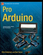
The game that you will set up in section is a simple game that challenges reaction time by making the player stop a sweeping series of LEDs at a specified point within the series. The game is called Stop It, and the main part of this game is the display with the sweeping of a single-light LED from one side of a series to the other. The challenge for this game is the amount of time a player has to react. The game appears to move faster when the time a single LED is on before the next one lights up is lowered. To achieve a level completion the player has to press a button while a specified LED is on. Stop it will use 11 LEDs and a single button; the winning LED is in the middle, and five LEDs are on either side.
After each level is complete or micro-win, Stop It will decrease the time each LED is on before moving on to the next stage. A micro-win will flash an alternating pattern on the LEDs, and after 11 micro-wins, a more elaborate pattern will flash, signifying a big win. If an attempt fails, Stop it will reset back to the first level, and the succession to the big win will be restarted. The flash of the LEDs is the reward for the proof of concept. If Stop it were to be developed in to a full arcade game, the reward would have to be greater than just flashing lights. For example, you might add 1 point to a score or money to a jackpot for every micro-win, and reward the player with tickets for each big win. Stop it will also need a risk for the user to place up front to attempt to play. For example, a number of tokens could be accepted via a coin acceptor before the player is allowed play.
Proof of Concept
Stop It’s proof-of-concept setup is described in Figure 11-1, with 11 1kΩ resistors connected to 5V power and then to the anode side of 11 LEDs. The cathode side of each LED is connected to pins 3 through 13—one cathode per pin. The LEDs will be on when the pin is pulled low, instead of when the pin is high. Turning on the LEDs by grounding is a best practice for lowering the amp draw though the microcontroller. A button is connected to ground on one side and pin 2 on the other so that the interrupt can be utilized to determine when the player has made an attempt to win. Serial is not used for this code, but the pins are left alone so that the serial can be used to communicate to other modules. It is possible to use a couple of shift registers to lessen the pin usage of the Arduino and allow for other devices to connect to digital pins. This example does not use shift registers, keeping the parts requirement to a minimum.
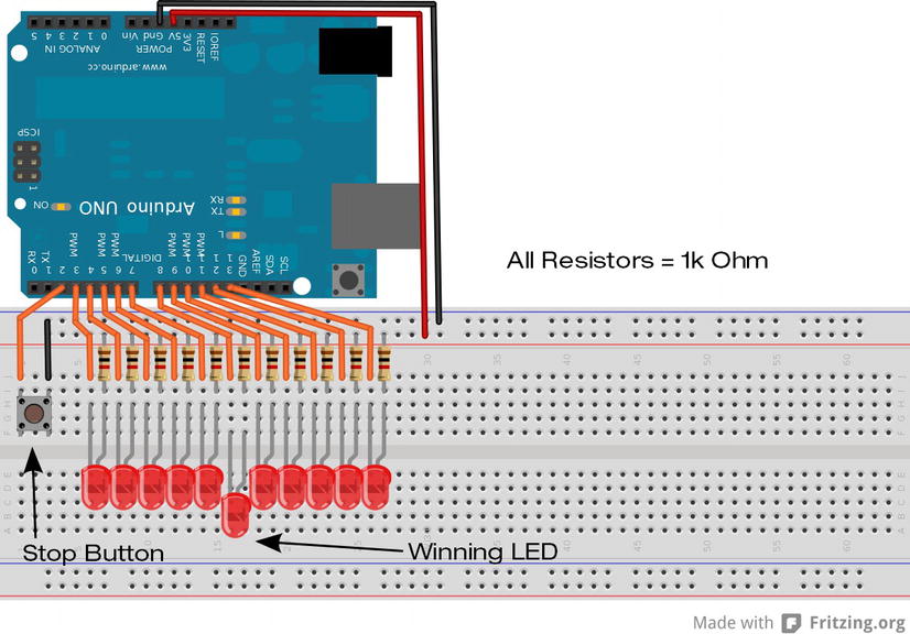
Figure 11-1 . Stop it’s proof-of-concept setup
There are two common methods to accomplish the sweep of an LED in a series:
- The first uses an array to hold the state of each LED and uses a loop to perform a series of digital writes to each individual pin.
- The other method is to directly manipulate the pin registers.
The register method is used for Stop it because it simplifies the program’s logic. Register manipulation was introduced in Chapter 6 to create a fast 10-bit digital-to-analog converter. The method for changing the pin state is the same: a single integer is used to hold the pattern that will be used to turn on or off the pins using bitwise shifts along with AND masks to turn the entire register at once. Stop it’s code, shown in Listing 11-1, is broken up into 11 parts and contains 12 functions.
Coding Stop It
Part 1 of Listing 11-1 sets up the variables for Stop it and the pins’ data direction. The proof of concept has five variables in total: one integer, one byte, and three Booleans. The integer is used to manipulate the pattern of the LEDs; this variable is used for everything that will be displayed to the user, and also to determine the direction of the sweep and whether a win has been archived. The byte variable is used to determine the level and to increase the speed of the sweep. The Booleans are used as flags to tell what direction the sweep needs to travel, and tell if a win condition has been achieved and if the button has been pressed.
Listing 11-1. Stop It’s Code, Part 1 of 11
int LEDshift = 0x0001;     // holds the LED pattern
boolean RightLeft = false; // true for right
boolean Win = false;       // when true, a win state has be achived
boolean button = false;    // flag if the button has been pressed
byte level = 0;            // curent level holder

void setup() {
  DDRD = DDRD | B11111000; // pins 3 - 7 set data direction
  DDRB = DDRB | B00111111; //  pins 8 - 13
  digitalWrite(2,HIGH);    // pull up so the input can be signaled on a low transition
}
The code for part 2 of Stop it is the function to perform the LED sweep. The moveLED() function is called from the main loop. The function first checks if the ON LED is at the first or last LED of the display. The check is performed by AND masking the LEDshift variable. If the mask equals anything other than zero, then the check is true, and depending on which mask is true, you set the flag RightLeft to the proper direction. The function then checks the RightLeft direction variable to bit shift the LEDshift over one every time the moveLED() function is called. The function then calls the displayLED() function.
Listing 11-1. Stop It’s Code, Part 2 of 11
void moveLED() {
  if (LEDshift & 0x0002) {
    RightLeft = false;
  }
  if (LEDshift & 0x0800) {
    RightLeft = true;
  }
  if (!RightLeft ) {
    LEDshift = LEDshift  << 1;
  }
  if (RightLeft) {
    LEDshift = LEDshift   >> 1;
  }
  displayLED();
}  // end  moveLED
The displayLED() function is part 3 for Listing 11-1. This function is responsible for changing the actual pin states to control the LEDs. When the displayLED() function is called, the LEDshift variable is parsed and split to match to the pins that are connected to the LED array. To get the LEDs that are connected to pins 3 through 7, the LEDshift variable is masked against a number that correlates to the position of the bits needed, and the result is then shifted to the left by two positions so that the final result is in the proper position for the pins. Before the total result is written to the register, a NOT operation is performed so that the pins will be in the proper state for the LED.
Listing 11-1. Stop It’s Code, Part 3 of 11
void displayLED() {
  PORTD =  ∼((LEDshift & 0x003E) << 2); // format and place the proper bits into the registers
  PORTB =  ∼((LEDshift & 0x0FC0) >> 6); // portd = low portb = hi
}
Part 4 is the function that will be used for the interrupt when the player attempts to stop the LED. This function is held in a loop while the button attached to pin 2 is depressed. The while loop of this function helps to debounce the interrupt because delays do not work inside of interrupts. The function sets the button flag, signifying that the player has made an attempt to stop it. A check of the LEDshift variable verifies that the winning LED is on; this is done by an AND mask. If the proper LED is on, the flag is set to true; otherwise, the flag remains false and will trigger a win or a loss condition when returning from this function.
Listing 11-1. Stop It’s Code, Part 4 of 11
void Button(){
  while (digitalRead(2)== LOW) {
    button = true;
    if ((LEDshift & 0x0040)) {
      Win = true;
    }
    else {
      Win = false;
    }
  } // end while
} // end button
Part 5 is the function to check if a button event is a win or a loss. This function is called from the main loop only when a button flag is true. The level gets incremented if a win or a big win is achieved. A big win is achieved when the LED has been stopped 11 successful times. This function calls the flashWin() function for every successful stop and the BigWin() function for 11 in a row. The level is incremented for every win. If the player does not stop the LED on the winning point, the function will call the notWin() function to reset the levels and provide the player with the feedback that they have lost.
Listing 11-1. Stop It’s Code, Part 5 of 11
void checkWin() {
  if (Win) {
    if (level < 10) {
      flashWin();
    }
    if (level >= 10) {
      BigWin();
    }
    IncreaseLevel();
  }
  if (!Win) {
    notWin();
  }
  resetPlay ();
} // end checkWin
flashWin() is the function that makes up part 6 of the code for Stop it. This function is a reward for the player. A binary pattern is first loaded in to the LEDshift variable of alternating 1s and 0s. Then a loop is used to invert the LEDshift variable, turning 1s into 0s and vice versa. The pattern is displayed by calling the displayLED() function and waiting until the player can see the pattern before continuing through the loop a total of ten times.
Listing 11-1. Stop It’s Code, Part 6 of 11
void flashWin() {
  delay (100);
  LEDshift = 0xFAAA;
  for ( int i = 0 ; i < 10; i++) {
    LEDshift = ∼LEDshift;
    displayLED();
    delay (100);
  }
} // end flashWin
The BigWin() function of part 7 is called when the player makes 11 successful wins. This function first calls the flashWin() function and then loads a new pattern, starting from the center LED and radiating outward, turning on all the LEDs. The function does this four times before finishing up with another flashWin().
Listing 11-1. Stop It’s Code, Part 7 of 11
void BigWin () {
  flashWin();
  for (int i = 0 ; i < 4 ; i++) {
    LEDshift = 0x0040; // turn on the center LED
    displayLED();
    delay (100);
    for (int i = 0 ; i < 6 ; i++) {
      LEDshift = LEDshift  | (1<< 5 - i); // radiate from the center by a logical OR of the 1s
                                          // into the
      LEDshift = LEDshift  | (1<< 7 + i); // LEDshift variable
      displayLED();
      delay (25);
    }
  }
  flashWin();
} // end BigWin
Every game has to have a condition for not winning. Part 8 of Listing 11-1 is the notWin() function. The notWin() function resets the level back to zero and sweeps the LED from right to left. The loop to display the pattern shifts the LEDshift variable to the left by 1, and then increments the variable till the loop is finished.
Listing 11-1. Stop It’s Code, Part 8 of 11
void notWin() {
  level = 0;
  delay (100);
  LEDshift = 0x0001;
  for ( int i = 0 ; i < 11; i++) {
  LEDshift = LEDshift << 1;
    LEDshift++;
    displayLED();
    delay (100);
  }
} // end notWin
Part 9 is the DspLevel() function, which informs the player what level they are now on. This function is called before the game starts the next level. This function works in the opposite way to the notWin() function, by shifting from left to right. In the loop, 1 is added to the high bit of the LEDshift variable by an OR of 0x1000, then bit shifting the variable LEDshift to the right by 1. The loop will run as many times as there are levels.
Listing 11-1. Stop It’s Code, Part 9 of 11
void DspLevel() {
  LEDshift = 0x0000;
  for (int i = 0 ; i <= level ; i++) {
    LEDshift = LEDshift | 0x1000; // add 1 to the high bits of LEDshift
    LEDshift = LEDshift >> 1 ;
    displayLED();
    delay (50);
  }
  delay (500);
} // end DspLevel
In part 10 of Listing 11-1 are the two functions to handle the resetting of game play for each level after the reward and loss patterns are displayed. Listing 11-1 also includes a function to increment the level after a win condition. The resetPlay() function first calls the DspLevel() function, and then resets all of the game condition variables to their initial state. The level variable is not reset in this function, but is a condition of a loss.
When the IncreaseLevel() function is called, the level variable is incremented by 1. This function also handles the reset to level 0 if the player can make it past level 15; the reset is done by an AND mask. The level variable helps set the speed of the LED sweep and needs to be kept below a certain number; otherwise, the time the LED stays on goes negative and can halt the Arduino. The level reset in this function is also independent of the loss condition reset.
Listing 11-1. Stop It’s Code, Part 10 of 11
void resetPlay () {
  DspLevel();
  Win = false;
  button = false;
  LEDshift = 0x0001;
  RightLeft = false;
}

void IncreaseLevel() {
  level++;
  level = level & 0x0F;// reset level when greater than 15
}
The last function (shown in part 11 of Listing 11-1) is the main loop that sets the game into motion and ties together all the functions of Listing 11-1. The first thing the loop() function does is to detach the interrupts so that the player cannot cause false wins or losses. The interrupts are not turned off by the noInterrupts() function, because that would stop the delay() function from working. Once the interrupts have been turned off, the button press and win state flags are checked for handling. After the check for a win or loss, the loop() function moves the ON LED to the next LED in the current direction it is traveling. The moveLED() function handles the movement and direction changes of all the LEDs. After the new LED is on, the interrupt for the button() function is turned back on, followed by a call to a delay.
The time the delay provides is the amount of time that any one LED is on before going to the next LED in the display; this is also the amount of time the player has to react to stop the LED sweep. The time for the delay is set by subtracting the level times 6 from 100. With the first level being equal to 0, the delay will be 100 ms, and every subsequent level shortens the time by 6 ms. the big win occurs after level 11 has been passed; that level has a time of 40 ms between LEDs. This delay sets the difficulty of getting a win a larger delay make the game easier and smaller is more difficult. The difficulty needs to be balanced for the intended audience, and is usually determined by age for arcade games. Games that are for children are often really easy for adults.
![]() Note It is important that the delay never goes negative; otherwise, the program will freeze up. Stop it allows a level up to 15 before resetting at a delay 10 ms; at this delay time, it is unlikely that a human player can achieve a win.
Note It is important that the delay never goes negative; otherwise, the program will freeze up. Stop it allows a level up to 15 before resetting at a delay 10 ms; at this delay time, it is unlikely that a human player can achieve a win.
Listing 11-1. Stop It’s Code, Part 11 of 11
void loop() {
detachInterrupt(0);
if (button == true) {
 checkWin();
}
moveLED();
attachInterrupt(0, Button, LOW);
delay  ( 100 - (level*6));
}
Stop it is ready to play after an Arduino is connected to the LEDs and button, as per Figure 11-1 (shown previously in the chapter). Upload all 11 parts of Listing 11-1 as a single Arduino sketch. Once the upload is finished, the game should start sweeping one LED from one side of the display. Depending on the color of the LEDs used, the display may be reminiscent of the front of a certain black 1980s sports car with artificial intelligence.
Begin the game by testing your skill, and try to Stop It on the center LED by pressing the button when the center LED is ON. The code should react as describe earlier. Since it may not be easy to test all the way to a big win, this game has a developer (or cheat mode) built in. To enter developer mode and ensure that the code is behaving properly, connect the ground side of the switch to the cathode side of the winning LED. Developer mode will make the button only trigger the interrupt when the center LED is on. Developer mode makes it possible to cycle though all of the levels and back to the first one.
Dirty Little Tricks,
Not to detract from the excitement of developing arcade games, but it is worth mentioning the unfair advantage known as rigging that some arcade games might have built into them. Such rigging only allows prizes to be won after certain conditions are met other than those presented within the game (some games never allow prizes to be won at all). This is like the belief that slot machine will only pay out a jack pot when it has received a certain dollar amount. Because arcade games are not regulated the same way as gambling machines, the possible use of rigged mechanisms has led to some controversy about legalities. Rigging is an unfortunate practice that takes away from a game’s entertainment value and in some places can be illegal. Rigging may come up when developing a redemption or merchandiser game for a client.
It is best practice to make a game as fair as possible but it is up to the developer’s judgment. Players will feel cheated when a rigged game is discovered. If the players have an enjoyable gaming experience, they will return to play more games. Games can be challenging, and as long as the players skill is the only factor keeping the player from winning.
As a game developer be-careful about developing games that are chance based and give prizes, as this can be considered a gambling machine and is highly regulated. But don’t be afraid to develop games that provide prizes; it is usually the monetary value of the prize and the frequency that a prize can be won that determines if a game is classified as a gambling machine. A game that always gives a ticket, a piece of candy or a small toy just for starting the game and the game gives more prizes out the longer the player plays is usually not considered gambling because something is awarded for every play and in some cases just putting in a token will award some tickets. Alley roll is an example of this; most alley roll games will provide one ticket for getting the ball to the other end, but if the ball makes it into a scoring ring, more tickets are awarded. However, it is always best to research the laws and regulations when building games that give out prizes.
Adding Better Displays and Graphics
A lot of unique games can be made with displays made of arrays of LEDs, mechanical flip dots, character LCDs, or small LCD panels. The games made with displays of these styles can sometimes lack the extra shine that may be desired from a television or a computer monitor. The Arduino with a couple of resistors can drive a television using the TV out library (www.arduino.cc/playground/Main/TVout), but is only capable of providing black-and-white images and only works with devices that have an RCA connection. To have the power to drive more complex graphics, additional hardware—a graphics processing unit (GPU)—is required.
The Gameduino was designed to be a GPU for the Arduino and is a shield that provides a graphics platform that can create complex graphics and animations. The Gameduino’s processor is programmed in to a Xilinx Spartan Field Programmable Gate Array (FPGA) and can connect to any microcontroller that is capable of SPI communication, even though it is packaged as a standard Arduino shield. The Gameduino can output video to a VGA-comparable display at 400×300 pixels with 512 colors, and can fully draw sprites, bitmaps, and backgrounds and generate stereo sound. The Gameduino is compatible with computer monitors with at least 800×600 resolution. The graphics capabilities of the Gameduino are very similar to 1980s video game consoles and older arcade games. The Gameduino also includes a secondary coprocessor that is independent of the main graphics functionality and is used to generate bitmaps for wireframe effects and control the video registers to create split-screen games.
The use of the Gameduino offloads all the graphics and display functions from the Arduino, leaving the Arduino free to control the game logic, handle user input, and track game progress. The Arduino initializes the Gameduino by copying to RAM all image data, sound data, and, if necessary, programming for the secondary processor to the Gameduino’s memory. The Gameduino has 32 KB of internal memory and is split up into background images, sprite images, and program space.
This chapter just introduces the Gameduino basics to show you how to build a functional game. Gameduino reference material is available at www.excamera.com/sphinx/gameduino/ and has samples and tutorials for more complex game feature, such as split screen and 3D wireframe. Download the quick-reference poster for working with the example in this section from the above site. The Gameduino is available at many online retailers, such as SparkFun Electronics, Adafruit Industries, and Jameco electronics.
Gameduino Library
The Gameduino is a SPI device that you can run the with standard SPI communication practices mentioned in Chapter 10. But for ease of getting games working quickly, the Gameduino library will be used for this section, and is available on the Gameduino’s website (www.excamera.com/files/gameduino/synth/sketches/Gameduino.zip). The library installs in the standard Arduino location and needs to be modified to work with the Arduino 1.0.1 and above IDE.
To make the Gameduino library compatible, the include "Wprogram.h" in the beginning of GD.cpp needs to be changed to include Arduino.h; this can be done in any text editor.
The following list is a reference of the most common functions that will be used from the Gameduino’s library. All of the functions can be called with a preceding GD. before the function call.
- begin(): Starts a connection to the Gameduino; returns true if successful.
- rd(address): Returns a byte read from the Gameduino’s memory located at address.
- wr(address, data): Writes a byte of data to the Gameduino’s memory at specified address.
- rd16(address): Same as rd(), but reads 16 bits from memory, instead of 8 bits, at address and address +1.
- wr16(address, data): Writes 16 bits to memory.
- fill(address, data, amount): Copies 1 byte to consecutive memory addresses up to amount.
- copy(address, data pointer, amount): Copies data from the Arduino’s memory to a Gameduino address.
- setpal(palette, RGB): Sets the character color palette.
- RGB(R, G, B): Converts RGB byte values to 15-bit encoding for the Gameduino.
- sprite(sprite #, position x, position y, image #, palette, rotation, collision): Tells the Gameduino to draw a sprite to the display. Table 11-1 describes the parameters for drawing sprites to the display.
Table 11-1. Arguments for the sprite() Function
Parameter Description sprite # Onscreen sprite number that addresses the individual sprite value between 0 and 255 position x Horizontal sprite position value between 0 and 511; 0 is the left edge of screen position y Vertical sprite position on the screen value between 0 and 511; 0 is the top edge of screen image # Selects a background sprite to display from The Gameduino’s RAM value between 0 and 63 palette Color palette to use when rendering the sprite value between 0 and15 rotation Sets the rotation and flip of the sprite collision Sets the collision detect flag - sprite2x2(sprite #, position x, position y, image #, palette, rotation, collision): Sets a 2×2 sprite to be drawn at the center four corners; uses same parameters as sprite().
- ascii(): Loads Gameduino’s standard font.
- putstr(position x, position y, string): Prints a string encapsulated in quotes at the position (x, y). Needs ascii() to be run first to load the default font.
- voice(voice #, wave type, frequency, left volume, right volume): Sets a tone to be played out of the Gameduino’s audio port. Table 11-2 describes the voice() parameters.
Table 11-2. Arguments for the voice() Function
Parameter Description voice # Individual hardware voice number used to output sound; takes a value between 0 and 63 wave type Waveform (0 is sine wave, 1 is noise) frequency Frequency in quarter-Hertz (e.g., 100 Hz is 400) left volume, right volume Amplitude of the wave output per channel; takes a value between 0 and 255; total volume for all voices should be less than or equal to 255
Some of the functions require a memory address to be able to read or place data into the Gameduino. The library also defines some keywords that are helpful when calling functions that deal with memory addresses. Table 11-3 provides the name, address, and descriptor; the keywords referenced are the common memory locations for developing games.
Table 11-3. Useful Keywords Specific to the Gameduino’s memory sructure and begging adresse locations. memory addresses * Byte length = total bytes in memory
| Keyword | Address | Description |
|---|---|---|
| RAM_CHR | 0x1000 | Screen characters (256 ×16 = 4096 bytes) |
| RAM_PAL | 0x2000 | Screen character palette (256×8 = 2048 bytes) |
| RAM_SPR | 0x3000 | Sprite control (512×4 = 2048 bytes) |
| RAM_SPRPAL | 0x3800 | Sprite palettes (4×256 = 2048 bytes) |
| RAM_SPRIMG | 0x4000 | Sprite image (64×256 = 16384 bytes) |
| PALETTE16A | 0x2840 | 16-color palette RAM A (32 bytes) |
| PALETTE16B | 0x2860 | 16-color palette RAM B (32 bytes) |
| PALETTE4A | 0x2880 | 4-color palette RAM A (8 bytes) |
| PALETTE4B | 0x2888 | 4-color palette RAM A (8 bytes) |
| VOICES | 0x2a00 | Voice controls |
A New Stop It
Building on top of other working projects is a great way to help simplify the development of more complex projects. The game for this section takes the idea of Stop it and expands it into the second dimension. The new game, called Stack It, as almost the same challenge as Stop It, but instead of requiring the player to stop a scrolling LED, Stack it uses scrolling sprites that need to be stopped when the current moving sprites are in the same position as the past sprites. Stack it speeds up and moves to the next level up the screen instead of displaying the level between each win.
There are two mechanisms of difficulty:
- The speed of the row
- The number of sprites that need to be matched
If the player misses the position of the previous row, the game removes sprites for the next level until the player has no more sprites left to play. Figure 11-2 shows the game play of Stack it with the last level still in play. The first level is always a gimme; it allows the player to decide where to start the stack and then continue through 16 levels to a big win.

Figure 11-2 . Stack it’s game play
The hardware setup for Stack it includes the Gameduino and a button; Figure 11-3 shows the setup for the Arduino. You need to plug the Gameduino into the Arduino, making sure to align the pins and one lead of a button connected to ground, and the other lead connected to pin 2 in the headers of the Gameduino. The Gameduino only uses digital pins 9, 11, 12, and 13. Pin 9 is the slave select and is unavailable for any other function. Pins 11, 12, and 13 are the standard SPI connections and can be used to connect other SPI devices, such as SD cards. The power for the Gameduino comes from the 3.3V, 5V, and ground of the Arduino and requires no extra connectors. The Gameduino can be connected to a monitor or a television with a VGA port.
![]() Note Some televisions may not be compatible with the Gameduino’s signal. For best results, use a monitor that is capable of 800×600 resolutions and has 4:3 aspect ratio. You can try a VGA-to-HDMI converter if no analog display inputs are available.
Note Some televisions may not be compatible with the Gameduino’s signal. For best results, use a monitor that is capable of 800×600 resolutions and has 4:3 aspect ratio. You can try a VGA-to-HDMI converter if no analog display inputs are available.
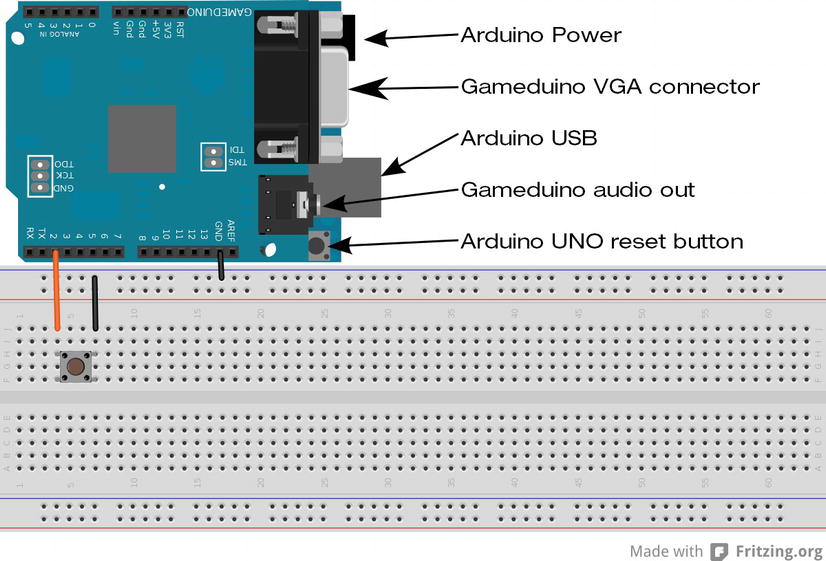
Figure 11-3 . Stack it’s hardware configuration
Art
When developing a game, the art and graphics usually don’t get finished till the all the game mechanisms are working. On the Gameduino, however, some graphics need to be available for display so that the game mechanisms can be developed. The graphics can be a placeholder or a simplistic version of what might be the final graphic. If game is a side-scroller, the player controls a main character that is an animated sprite. For initial development, the sprite can be just a single frame of the animation. Stack it only uses one sprite and the background doesn’t move.
Art for the Gameduino uses a special format that needs to be converted from an existing file or hand coded. Each sprite is 16×16 pixels. The Gameduino does not store each sprite with the color information, but instead uses a separate color palette and draws sprites to the screen in a way similar to color-by-numbers. The Gameduino offers three palette types 4, 16, or 256 and describe the amount of different colors that the palette can hold. The use of the palettes saves memory because each color needs 16 bits and is in ARGB1555 format and if the color information was saved in every pixel, 64 sprites would need 32 KB of memory, as compared to the 16.5 KB used by the separate color palette. Figure 11-4 illustrates the ARGB color format used to create color; bit 15 is the flag for transparency and each of the five bits for R, G, and B. The Gameduino is little-endian when it comes to memory; the lower bits (0 through 7) need to be copied to the address and the higher bits (8 through 15) are copied to the address plus 1.
![]()
Figure 11-4 . ARGB 1555 color format
The sprite used for Stack it is illustrated in Figure 11-5, using the coding to the 4-color palette. Each sprite maps 1 byte to the color palette per pixel. One sprite can be made with a 265-color palette, two sprites with a 16-color palette, and four sprites with a 4-color palette. Using the 4-color palette allows more sprites to be in memory, because it takes 2 bits to map to a color, and 8 bits are available. Each 2 bits of the sprite map can describe a different color used; this is good for space saving and making animated sprites. When multiple sprites are combines in one map, they can be added to the screen by changing the palette argument when calling the sprite() function. Larger graphics can be made by placing two or more sprites side by side on the screen.

Figure 11-5 . Stack it’ s sprite with palette coding
Figure 11-6 illustrates the color palette used for Stack it. It consists of the colors black, red, green, and blue. Any color value can be used, however There is a limit to amount of different colors that the palette can hold. Stack It’s sprite only uses three of the four colors available. You can give sprites transparent pixels by setting bit 15 to 1 on one of the colors. When transparency is used, the color information for R, G, and B are ignored and only one color needs to be transparent. Transparency allows for background colors to show; this is useful for non-square character sprite move over a changing background the background.
Figure 11-6 . Four-color palette using black, red, green, and blue (from left to right)
The Gameduino Tools Online page (http://gameduino.com/tools) offers three great tools that convert image files to the proper coding to avoid hand coding sprites, backgrounds and lossy images. The tool also provides an Arduino sketch to quickly check the sprites on the display before putting them in a game. The tool provides a .h file that contains the converted image. The three types of conversions tools background, sprite sheets and lossy image conversion requires an image to convert. The sprite sheet tool also has options for the sprite size and color palette type.
The easiest way to get started making sprites is to use GIMP (www.gimp.org/)—free, open source image manipulation software that is capable of creating PNG files. When creating a new sprite image, it is best to work at the actual pixel size and with dimensions in multiples of 16. Multiple different sprites can be made in one file, and the conversion tool will divide them up according to the settings. Note that the conversion tool may not always get the colors perfect and manual manipulation of the palette may be required in the Arduino sketch.
Coding Stack It
To get started coding Stack it, create a new sketch and add a new file within the Arduino IDE by pressing Ctrl+Shift+N, and enter cube.h when prompted. Listing 11-2 contains the converted image from the Gameduino image tool—the variables names in cube.h are generated by the image tool. Listing 11-2 uses only the image information and does not include the function that is autogenerated by the image tool. Two static arrays are declared in cube.h. The first is cube_sprimg[], which is the mapping to the color palette, and the other is cube_sprpal[]. The bytes set in both cube_sprimg[] and cube_sprpal[] are in the order they will be loaded into the Gameduino’s memory. Because of the little-endian mode of the Gameduino, the palette has the lower byte of the color set before the higher byte.
Listing 11-2. Sprite Code for Stack It
static PROGMEM prog_uchar cube_sprimg[] = {
0x00,0x00,0x00,0x00,0x00,0x00,0x00,0x00,0x00,0x00,0x00,0x00,0x00,0x00,0x00,0x00,
0x00,0x00,0x00,0x00,0x00,0x00,0x00,0x00,0x00,0x00,0x00,0x00,0x00,0x00,0x00,0x00,
0x00,0x00,0x02,0x02,0x02,0x02,0x02,0x02,0x02,0x02,0x02,0x02,0x02,0x02,0x00,0x00,
0x00,0x00,0x02,0x02,0x02,0x02,0x02,0x02,0x02,0x02,0x02,0x02,0x02,0x02,0x00,0x00,
0x00,0x00,0x02,0x02,0x02,0x02,0x02,0x02,0x02,0x02,0x02,0x02,0x02,0x02,0x00,0x00,
0x00,0x00,0x02,0x02,0x02,0x02,0x01,0x01,0x01,0x01,0x02,0x02,0x02,0x02,0x00,0x00,
0x00,0x00,0x02,0x02,0x02,0x01,0x01,0x01,0x01,0x01,0x01,0x02,0x02,0x02,0x00,0x00,
0x00,0x00,0x02,0x02,0x02,0x01,0x01,0x01,0x01,0x01,0x01,0x02,0x02,0x02,0x00,0x00,
0x00,0x00,0x02,0x02,0x02,0x01,0x01,0x01,0x01,0x01,0x01,0x02,0x02,0x02,0x00,0x00,
0x00,0x00,0x02,0x02,0x02,0x01,0x01,0x01,0x01,0x01,0x01,0x02,0x02,0x02,0x00,0x00,
0x00,0x00,0x02,0x02,0x02,0x02,0x01,0x01,0x01,0x01,0x02,0x02,0x02,0x02,0x00,0x00,
0x00,0x00,0x02,0x02,0x02,0x02,0x02,0x02,0x02,0x02,0x02,0x02,0x02,0x02,0x00,0x00,
0x00,0x00,0x02,0x02,0x02,0x02,0x02,0x02,0x02,0x02,0x02,0x02,0x02,0x02,0x00,0x00,
0x00,0x00,0x02,0x02,0x02,0x02,0x02,0x02,0x02,0x02,0x02,0x02,0x02,0x02,0x00,0x00,
0x00,0x00,0x00,0x00,0x00,0x00,0x00,0x00,0x00,0x00,0x00,0x00,0x00,0x00,0x00,0x00,
0x00,0x00,0x00,0x00,0x00,0x00,0x00,0x00,0x00,0x00,0x00,0x00,0x00,0x00,0x00,0x00,
};

static PROGMEM prog_uchar cube_sprpal[] = {
0x00,0x00,  0x00,0x7c,  0xe0,0x03,  0xff,0xff,
};
With the sprite for Stack it ready, the game-play code can be added. Stack it shares a similar concept with Stop it and also shares similar coding methods for the game mechanisms. Listing 11-3 is entered in to the main part of the sketch and is broken up into seven parts. Part 1 of Stack it sets up the variable decorations, includes, and the setup() function. The Gameduino library (GD.h), SPI library (SPI.h), and cube header (cube.h) needs to be included to have access to the functions used by Stack It. The cube.h file is included with quotes instead of < >, signaling the compiler to look for a local file in the sketch folder instead of searching for the header file in a library location. The order of the library includes is important; the SPI.h include comes before cube.h, and GD.h is the last include.
Listing 11-3. Stack It’s Sketch, Part 1 of 7
#include <SPI.h>
#include "cube.h"
#include <GD.h>

long cubeMove[18];
boolean RightLeft;
boolean Win = false;
boolean button = false;
int level = 0;

long initPattern = 0x0000001f;

void setup() {
  pinMode(2,INPUT);
  digitalWrite(2,HIGH);
  GD.begin();
  GD.copy(PALETTE4A, cube_sprpal, sizeof(cube_sprpal));
  GD.copy(RAM_SPRIMG, cube_sprimg, sizeof(cube_sprimg));
  resetPlay();
}  // end setup
The integer that was the LEDshift variable in Stop it is changed to a long array; this is to account for the increased number of elements that can be displayed on the screen. The array is declared as size 18 so that every level can be accounted for when displaying the sprites. The flags for the win, direction, and button press serve the same function as those used in Stop It. A variable that stores the initial pattern that will be used for the first level of the game is created here. The binary pattern of the variable is used when displaying the sprites. The pattern of the bits can be used to make the game more challenging the more bits that are placed consecutively will provide an easier challenge, allowing for the player to miss the target more often. The bit pattern does not have to be consecutive making the game more interesting. Remember that the Gameduino can only have 256 sprites on the screen at any given moment, so choose an initial pattern that will keep the sprite count below 256. There are 17 levels of Stack it, but 18 array positions—one of the array positions is used to create a base at the bottom of the screen below the first level and will use 24 of the available sprites.
The setup() function prepares the Arduino pin that will be used for the button, and is similar to the setup function as used in Stop it. The setup function adds the initialization of the Gameduino and copies the sprite and palette to memory. The memory locations used is the first four-color palette and the start of the sprite RAM section. The image is copied from the cube.h variables. The final step in the setup() function is to call resetPlay() to make sure the game is ready to play.
The function for part 2 is responsible for shifting the row of sprites from one side of the display to the other. The RowShift() function is almost identical to the moveLED() function for Stop it; it checks for when the bit-shift reaches the existents of the screen changing the bit-shift direction. The only change accounts for the increased bits used for the position, and the level determines what position of the array is currently in play.
Listing 11-3. Stack It’s Sketch, Part 2 of 7
void RowShift() {
  if (cubeMove[16-level] & 0x00000001){
    RightLeft = false;
  }
  if (cubeMove[16-level] & 0x00800000){
    RightLeft = true;
  }
  if (!RightLeft ){
    cubeMove[16-level] = cubeMove[16-level]  << 1;
  }
  if (RightLeft){
    cubeMove[16-level] = cubeMove[16-level]  >> 1;
  }
} // end row shift
The function that is responsible for displaying the game to the player is the same in functionality as the display function for Stop it, but is executed differently. The use of the Gameduino allows for dynamic positioning of game elements within the 400×300 pixel viewing area, and there are no registers to directly manipulate. Part 3 is the function for displaying all the sprites to the screen. The cubeMove array is used to hold the patterns that need to be displayed. Every time the displaySprites() function is called, it will display all the current values of cubeMove; A value of 1 equals a sprite, and a sprite will be displayed according to position within the array. The array is two dimensional there is a vertical and a horizontal component; the array position is the vertical and the individual bits within the variable makes up the horizontal position. Stepping through the array is done with one for loop, while a nested for loop shifts though the bits of the variable. When there is a 1 in the variable, a sprite is displayed, and when there is a 0, the loop continues to the next step. The position of the sprite on the screen is determined by what step each for loop is at, the sprite is 16×16 pixels. The step count of the for loops is multiplied by 16 so the sprites will be place side by side on the screen. A counter that is incremented when a 1 is found to keep track of the number of sprites being displayed and is used to create a dynamic sprite count for the Gameduino.
Listing 11-3. Stack It’s Sketch, Part 3 of 7
void displaySprites() {
  int spriteNum = 0; // start sprite count at 0
  for (int y = 0 ; y < 18 ; y ++ ) { // loop though the array for y positon
    for (int x = 0 ; x < 24 ; x ++) {  //  loop though the variable for x positon
      if ((cubeMove[y] >> x) & 0x00000001) { // check current variable position for a 1
        GD.sprite(spriteNum, (x* 16)+7, (y*16)+7 ,0, 8 , 0);
        spriteNum++;
      } // end if
    } // end for loop x
  } // end for loop y
} // end displaySprites
The buttonInterrupt() and WinState() functions implement part 4. buttonInterrupt() is called when the player attempts to win the current level and move on to the next. The interrupt is activated in the same fashion as in Stop it. buttonInterrupt() waits in a loop while the button is depressed and calls the WinState() function to determine if the player has won or not. The check for a win condition has been moved to a separate function to allow for possible other functions to check for win conditions outside of the player’s control. A win state is true if there is at least 1 bit in common between the current level and the prior level. The first level of the game is compared against the foundation bits in the cubeMove array. The first level is always a gimme, and allows the player to decide where the stack starts. If there are no common bits, the win state is false and the game is reset.
Listing 11-3. Stack It’s Sketch, Part 4 of 7
void buttonInterrupt  () {
  while ( digitalRead(2)== LOW) {
   WinState();
  }
} // end buttonInterrupt

void WinState() {
  button = true;
  if ((cubeMove[16-level] & cubeMove[17-level])) {
    Win = true;
  }
  else {
    Win = false;
  }
} // end WinState
Part 5 performs actions based on the win state when the player presses the button and increases the level. If the win state is true, then the prior level is masked with the current to determine the amount of sprites that are in common. If some of the sprites are not directly above the prior level, they get removed, and the new amount of sprites is copied to the next level, making it more difficult for the player along with decreasing the time the player has to react. If the win state is false, the game simply resets. The IncreaseLevel() function works like the one for Stop it, but the masking of the level count is unavailable because of the array. An if statement is used in place of the mask, and when the level reaches 17, the final pattern within cubeMove() is displayed and the game is reset. A reward function can be called at the point the level is maxed.
Listing 11-3. Stack It’s Sketch, Part 5 of 7
void checkWin() {
  if (Win) {
    // check prior level and set curent level to any misses and copy to next level
    cubeMove[15-level] = cubeMove[16-level] = cubeMove[16-level] & cubeMove[17-level];
    IncreaseLevel();
  }
  if (!Win) {
    resetPlay ();
  }
  button = false;
} // end checkWin

void IncreaseLevel() {
  level ++ ;
  if (level >= 17) {
    // display winning pattern and reset play
    displaySprites();
    delay (200);
    resetPlay();
  }
} // end IncreaseLevel
The resetPlay() function of part 6 ensures that the game is set back to the beginning and ready for a new attempt. The cubeMove array is first zeroed and loaded with the initial state. The Gameduino then needs the sprite buffer cleared, because sprites with a higher number than that currently produced from the cubeMove pattern will remain on the screen. A loop is used to step through all 256 possible sprites and tell the Gameduino to draw blank sprites off the screen.
Listing 11-3. Stack It’s Sketch, Part 6 of 7
void resetPlay () {
  for (int i = 0 ; i < 17 ; i ++) {
  cubeMove [i] = 0x00000000;
  }
  cubeMove[16] = initPattern;
  cubeMove[17] = 0x00ffffff;
  for (int i = 0 ; i < 256 ; i ++) {
  GD.sprite(i,450,450,0,0,0);
  }
  level = 0;
} // end resetPlay
As with Stop it, the final function is the loop (shown in part 7) sets the play into motion for the game. Other than the names of the functions that are called, this function is nearly identical to the one used in Stop it. To account for the increase in levels and the gimme level, the initial delay has been increased to 120 ms, leaving 18 ms for the player to react at the final level. Because of the increased complexity and the display speeds included with the Gameduino, the program spends a bit more time with the interrupt off.
Listing 11-3. Stack It’s Sketch, Part 7 of 7
void loop() {
  detachInterrupt(0);
  if (button) {
    checkWin();
  }
  RowShift();
  displaySprites();
  attachInterrupt(0, buttonInterrupt, LOW);
  delay (120 - ( level * 6));
} // end loop
At this point, the code for Stack it is ready for a trial run. Configure the hardware as per Figure 11-3 (shown earlier in the chapter), and load the sketch onto the Arduino. The game should start immediately after the upload is finished and display four sprites in a row sweeping from side to side above a full row of sprites at the bottom. Once the button is pressed, the current level will stop and move to the next level. Check to see if the game-loss functionality is working by failing to match up the sprites. The game should fully reset when the last sprite is lost. Stack it does not have a convenient developer mode like Stop it has; the final levels have to be reached naturally or the delay has to be increased to check the reset to the beginning from the final win.
![]() Note The SPI library is standard and included with the Arduino IDE. Go to the root directory, and then arduino/avr/libraries; also remember to fix the reference to Wprogram.h to point to Arduino.h within GD.cpp.
Note The SPI library is standard and included with the Arduino IDE. Go to the root directory, and then arduino/avr/libraries; also remember to fix the reference to Wprogram.h to point to Arduino.h within GD.cpp.
Making Sounds
The Gameduino has the capability to produce stereo sounds via the audio plug. The voice() function in the Gameduino library can play two different types of wave functions: a sine wave and noise. The frequency range is about 10 to 8,000 Hz via a 12-bit synthesizer. The Gameduino is capable of 64 different voices that combine to create the output. The total amplitude of all the playing voices’ output is a maximum value of 255 per channel—to avoid clipping, keep the total amplitude under 255. The frequency argument of the voices is in quarter-Hertz—for example, a frequency of 880 Hz (an A note) would require an input of 3,520. By adding the sine waves together simulated square and sawtooth waves can be created to better mimic the sound of old game systems. The noise wave in conjunction with sine waves can create sound effects for rockets, car engines, and even fighting games. Once the Gameduino is told to start making a sound, it will continue till told to change. The sound needs time to be heard by the listener, so there will have to be time delays in the code. This can slow down other aspects in the game. Note that changes should happen between running of loops, or in more advanced cases, run in the Gameduino’s secondary processor. Sound is a great way to give the player feedback on what is going on (e.g., for losing or completing a level, or to produce a sense of urgency at certain parts of the game).
Adding the first sound effect to Stack it provides an auditory signal when the button has been pressed, add the following code line to the beginning of buttonInterrupt() before the loop is entered to have the game make a sound when the button is pressed.
GD.voice(0, 0, 5000,254,254);
A sound of 1,250 Hz (approximately an E-flat) will start playing from both channels. To get the sound to turn off, add a corresponding call at the end of the buttonInterrupt() that would appear just before the buttonInterrupt() function returns:
GD.voice(0,0, 0,0,0);
Listing 11-4 describes three functions that produce more complicated sounds to inform the player of a loss, a big win, and that the game is currently being played.
The first sound function, moveTone(), plays three notes: 500 Hz (∼B), 750 Hz (∼F sharp), and 1,000 Hz (∼B + 1 octave). The note timings are based on the delay of the main loop. moveTone() generates sound that increases in tempo along with the increase in sweep speed of the sprite. The increase in the tempo as the game approaches the final level provides the feeling of greater urgency. moveTone() needs two global variables that are used to count the steps between note changes and to allow other functions to turn the move tone on and off. The variables are an integer and a Boolean declared at the beginning of the code, just after the include section.
int movetonecount = 0;
boolean moveToneflag = true;
Listing 11-4 is split into three parts. The moveTone(), WinTone(), and LossTone() functions are added to the end of the main sketch after the end of the loop() function. The call to moveTone() is at the end of the loop() function just before loop()’s ending curly bracket.
Listing 11-4. moveTone() Sound Functions for Stack It, Part 1 of 3
void moveTone() {
  if (moveToneflag) {
    if (movetonecount >= 2) {
    GD.voice(0, 0, movetonecount*1000,127,127);
    }
    if (movetonecount == 5){
    GD.voice(0, 0, 0,0,0);
    movetonecount = 0 ;
    }
    movetonecount++;
  } // end if moveToneflag
} // end moveTone
Listing 11-4 part 2 is the WinTone() sound function, and is used to signify the final win. WinTone() plays six tones (750 Hz, 1000 Hz, 1250 HZ, 1000 Hz, 750 Hz, and 500 Hz) twice in a row to give the player a pleasant audio reward for completion. The function should be called from the IncreaseLevel() function just after the call to dispaySprites() within the if statement used to roll the game back to the first level when the player surpasses the game limits.
Listing 11-4. moveTone() Sound Functions for Stack It, Part 2 of 3
void WinTone() {
  for (int t =0 ; t < 2 ; t ++) {
    for(int i = 3 ; i < 5 ; i++) {
      GD.voice(0, 0, i*1000,     254,    254);
      delay (150);
    }
    for(int i = 5 ; i > 1 ; i--) {
      GD.voice(0, 0, i*1000,254,254);;
      delay (150);
    }
    GD.voice(0, 0, 0,0,0);
  } // end for loop that plays the tone twice
} // end WinTone
In part 3, the third sound function, LossTone(), creates a sound that plays four notes in descending frequency: 1250 HZ, 1000 Hz, 750 Hz, and 500 Hz. This tone is only played once—when the player has missed the last sprite available. This function needs to be called from the checkWin() function inside the if statement that checking for a win before the play resets back to the first level.
Listing 11-4. moveTone() Sound Functions for Stack It, Part 3 of 3
void LossTone() {
  for(int i = 5 ; i > 1 ; i--) {
  GD.voice(0, 0, i*500,     254,    254);
  delay (150);
  }
  GD.voice(0, 0, 0,    0,    0);
} // end loss tone
Adding a Bit of Splash
After the sound is added to the game a bit of more ambience can be achieved by creating a splash screen so the game can advertise itself when it is turned on and is not being played. Stack it will display anything placed in the cubeMove array when displaySprites() is called. Adding a pattern to the screen is the same as Stop It’s method of showing status to the player. The two-dimensional nature of the Gameduino allows for the creation of text using the placement of sprites with a binary pattern loaded into the cubeMove array.
The stackIt() function in Listing 11-5 loads a second array with a binary pattern that represents the words STACK IT. The pattern is backward in the logo array because of how the displaySprites() function steps though the cubeMove array. The function copies and displays one row of the logo array to the cubeMove array every 300 μs; then the win tone is played before the game is prepared for play. The StackIt() function can be called in the setup() function, replacing the resetPlay() function call so that when the game starts, the logo will be displayed.
Listing 11-5. A Splash Function for Stack It
void StackIt() {
GD.voice(0, 0, 0,0,0);
  long logo[18];
  logo[0]  = 0x00000000;  // hex is revese pattern  1 = # 0 = .
  logo[1]  = 0x00498df6;  // .##.#####.##...##..#..#.
  logo[2]  = 0x002a5249;  // #..#..#..#..#.#..#.#.#..
  logo[3]  = 0x00185241;  // #.....#..#..#.#....##...
  logo[4]  = 0x00185e46;  // .##…#..####.#....##...
  logo[5]  = 0x00285248;  // ...#..#..#..#.#....#.#..
  logo[6]  = 0x004a5249;  // #..#..#..#..#.#..#.#..#.
  logo[7]  = 0x00899246;  // .##...#..#..#..##..#...#
  logo[8]  = 0x00000000;
  logo[9]  = 0x0003e7c0;  // ......#####..#####......
  logo[10] = 0x00008100;  // ........#......#........
  logo[11] = 0x00008100;  // ........#......#........
  logo[12] = 0x00008100;  // ........#......#........
  logo[13] = 0x00008100;  // ........#......#........
  logo[14] = 0x00008100;  // ........#......#........
  logo[15] = 0x000087c0;  // ......#####....#........
  logo[16] = 0x00000000;
  logo[17] = 0x00ffffff;  // ########################
  for (int i = 17 ; i >= 0 ; i --) {
    cubeMove[i] = logo[i];
      displaySprites();
      delay (300);
    }
  WinTone();
  delay (500);
  resetPlay();
} // end Stack it logo
Programming the Game to Play Itself
Most arcade games have a demo mode, which shows the game being played without a human player. Unlike console games, arcade machines are left on during business hours at an arcade. The demo mode entices a player to take part in the game and displays information on how to start playing. Listing 11-6 is split into three parts and demonstrates a method of adding self-play to Stack It. Most games just have a few set patterns that are played before displaying a splash screen; this can be accomplished by creating an array that holds the set patterns. This method would use a lot of program space, however; a procedural method of play, on the other hand, would use less program space and could provide a wider variation on the self-play patters. By utilizing functions used for a human player, Stack it could use random number generation to make decisions on game play. The random numbers could tell the selfPlay() function to call for a check of WinState() to simulate an actual button press.
Listing 11-6, part 1 is the main selfPlay() function, and is called from the loop just before the delay and after the interrupt function is attached. Every time selfPlay() is called, a check is performed to see if the loop has been executed for a sufficient amount of time without player interaction to initiate the self-play mode. The check is based on a count that increments every time selfPlay() is called and not activated; the count has been chosen to be a reasonable amount of time to consider the player inactive.
Listing 11-6. Self-Play for Stack It, Part 1 of 3
void selfPlay() {
  if (selfPlayCount >= 300) {
      detachInterrupt(0);
      attachInterrupt(0, exitSelfPlay, LOW);
      GD.putstr(0, 0, "PRESS BUTTON TO PLAY");
      moveToneflag = false;
      if (logoCount >= 51 ){
        StackIt();
        logoCount = 0;
      }
      randomSeed(analogRead(0));
      if (level == 0 && random(10) == 5){
        selfPlayButton();
      }
      else if ((cubeMove[16-level] == cubeMove[17-level])) {
        if (random(2) == 1){
        RowShift();
        delay (120 - ( level * 6));
        displaySprites();
      }
      if (random(2) == 1) {
        selfPlayButton();
      }
      } // end else if level check
  } // end if self play count check
  else {
      selfPlayCount++ ;
  }
} // end self play
selfPlay() checks to see if the current level is equal to the last level, and then randomly chooses to push the virtual button by comparing a randomly generated number to a chosen number and when the numbers match the virtual button is pressed. A perfect game will be played if the selfPlay() function can only press the virtual button when the current level is perfectly aligned with the last level even with randomly deciding when to press the virtual button. To add the feel of imperfection to the selfplay() function the same method used as to determine when to press the virtual button to randomly be off by one so that a perfect game is not guaranteed and selfPlay() can lose. When the game is playing, the first level will never equal the foundation level, and the virtual button call will never be activated. selfplay() has to has to trigger the virtual button at a random point to proceed from the first level. The random numbers are generated from seed that is created by reading the Arduino’s analog pin 0 while it is not connected and is electrically floating. When a generated random number is checked against a set number, corresponding events will be triggered in the self-play mode.
The move sound is turned off when the game is in self-play mode so that the game does not get irritating to people when it is idle. selfPlay() displays the splash screen every 51 virtual button presses, or about every three to five selfplay() games. The selfPlay() function attaches a different interrupt function to the physical button so that the self-play can be exited and the game can return to a playable state when a player wants to play it. A few things need to be set up in the beginning of the sketch to enable self-play. Two variables need to be initialized so that the program will know when to play the splash screen and to keep track of whether a player is not at the game. One of the variables is incremented when the self-play is called and is initialized to a value of 300 so the self-play functionality starts when the game is turned on. The other variable is incremented when the self-play presses the virtual button. Both variables are reset when a player engages the game. Add the following two variables to the global declarations after the library includes:
int logoCount = 0;
int selfPlayCount = 300;
A reset of the self-play count (selfPlayCount = 0) is added to the beginning of the buttonInterrupt() function so that the self-play will not be engaged while the player is in the middle of a game. Finally, a call is made to GD.ascii() before the call to StackIt() in the setup() function, allowing the game to use the standard Gameduino font. The font is used so that a string can be printed to the top-left corner of the display to inform a prospective player on how to start a new game.
Part 2 is the virtual button the self-play mode uses to advance the game. A tone is played that is similar when the physical button is pressed. The virtual button makes a call to WinState() to check if the self-play has matched the prior level. The self-play mode uses all the game play mechanisms and mimics an actual player. Self-play will not always win or play the same game every time. logoCount is incremented within this function to signal the splash screen to be displayed.
Listing 11-6. Self-Play for Stack It, Part 2 of 3
void selfPlayButton() {
  GD.voice(0, 0, 5000, 254, 254);
  delay (50);
  WinState();
  logoCount++;
  GD.voice(0,0,0,0,0);
} // end self play button
The game will return to a normal play mode because the self-play changes the interrupt function. Part 3 is for handling the returning to normal play when a player presses the button while the self-play mode is activated. The string is removed for the top of the screen, play is reset, the move sound is turned back on, and the counts are set to the appropriate states. The logo count is set to 51 so that self-play will execute after the game goes idle.
Listing 11-6. Self-Play for Stack It, Part 3 of 3
void exitSelfPlay(){
  GD.voice(0, 0, 5000,254 ,254);
  GD.putstr(0, 0, "                    ");
  while (digitalRead(2)== LOW){
  resetPlay();
  selfPlayCount = 0;
  logoCount = 51;
  moveToneflag = true;
  }
  GD.voice(0, 0, 0,   0 ,    0);
} // end exit self play
The Finishing Polish
With Listings 11-4 through 11-6 added to the initial Stack it code and working, the game has moved from a proof of concept to nearing completion. The sprites can be formalized, backgrounds can be created, and coin mechanisms and ticket dispensers can be integrated. The cabinet can be constructed and extras can be added to complete the game for an arcade. By working on small components and adding them to working components one at a time, a fairly complex game can be developed easily.
It is possible for games to quickly outgrow the Arduino Uno hardware by sheer number of pins or memory space. Using other hardware is always a viable solution, but it is always best to make an attempt to create something on less-equipped hardware. This helps developers create efficient code, which can always be ported to different systems. If the Arduino Uno is not capable, the next step for more pins and memory might be the Arduino Mega. If you’ve outgrown the Gameduino, you can modify the processor and upload it to a bigger Field Programmable Gate Array FPGA. Some clones of the Gameduino have also added extra RAM, such as the MOD-VGA made by Olimex (http://olimex.wordpress.com/).
The Gameduino is an SPI device and can be connected to any master SPI-capable device. Figure 11-7 shows how to connect the Gameduino shield to an Arduino Mega. This set up opens other opportunities for creating interesting gaming platforms for example integrating hardware such as the ADK Mega and Android devices with the graphics capabilities of the Gameduino. Stack It can be uploaded to an Arduino Mega without any changes to the code by selecting the proper board and connecting the Gameduino as per Figure 11-7.

Figure 11-7 . Gameduino to Arduino Mega
The following list provides some extra resources that might be helpful for further research into game construction and development. It includes examples of suppliers that handle arcade equipment and supplies. Some professional arcade game development companies are listed to provide an example of arcade games and the industry.
- www.artlum.com: This site has a lot of Gameduino projects, including a tutorial on how to connect a classic NES controller to an Arduino.
- www.brainwagon.org/the-arduino-n-gameduino-satellite-tracker: This is a wonderful nongame project that uses the Gameduino.
- www.adafruit.com/products/787 and www.adafruit.com/products/786: Provided here are two different coin mechanisms available from Adafruit industries.
- www.coinmech.com and www.imonex.com: These are two good sources for commercial-grade coin mechanisms.
- www.deltroniclabs.com: This company provides commercial-grade ticket dispersers.
- www.nationalticket.com and www.tokensdirect.com: These supply tickets and tokens for arcade machines.
- www.uniarcade.com, www.coinopexpress.com, and www.happmart.com: These companies offer various replacement arcade machine components, such as main boards and buttons.
- www.xgaming.com: This site offers other hardware game development systems, such as the Hydra gaming system.
- www.bmigaming.com, www.benchmarkgames.com, www.laigames.com, www.universal-space.com, and www.baytekgames.com: These are a few professional arcade game developers; these companies are a great cross section of the arcade games that are currently in use in a majority of arcades.
- www.iaapa.org: The International Association of Amusement Parks and Attractions (IAAPA) hosts a few conventions that show off the technology for arcades and amusement parks, and is a great resource for arcade game developers.
- www.paxsite.com and www.gencon.com: These are couple of large conventions that showcase games from many categories—including board, card, and computer games—from professional and independent developers alike. These conventions are not associated with the IAAPA.
Summary
Developing games of any type is rewarding, fun, and challenging. Game development is a field that combines artistry, storytelling, and many other skills. Starting a game is as simple as having an idea and breaking it down into small components that combine together for a final product. Taking ideas and building them into proofs of concept will help build a game portfolio that can be used to develop more complex games. An increasing number of independent developers are making good games thanks to more outlets for distribution and ease of obtaining skills and knowledge. Arduino development makes a viable platform for developing games because of the unique experience it can provide for any game type.