
![]()
XBees
Radio communication is a fundamental method of communicating over varying distances without having an encumbrance of wires. Arduino developers take advantage of radio communication in robotics, home automation, and remote-sensing applications. To avoid the headaches of developing radio communications systems from scratch, a lot of developers use XBee radio modules to add wireless functionality to projects. The XBee is a full-featured radio transceiver module made by Digi International (www.digi.com) and is compliant with FCC regulations as long as you use the module without modification and adhere to a few other restrictions.
The restrictions that apply to the use of the XBee by the FCC and by other countries are listed in the data sheet provided by Digi. Most XBee modules are also compliant with the ZigBee communication protocol, a standard based on the IEEE 802.15.4 standard. XBees have the ability to communicate with other ZigBee-compliant devices.
The minimum hardware to get started exploring the world of XBees is a USB adapter, a serial adapter, an Arduino-compatible board, and two XBee modules. You can use the USB XBee adapter sold by Adafruit Industries (www.adafruit.com/products/247) or the one sold by SparkFun Electronics (www.sparkfun.com/products/8687). The USB adapter is needed to interface with the computer for initialization and setup, and can provide a connection from the computer to other XBee modules.
The XBee has a small pin pitch that’s not breadboard compatible, and it’s a 3.3V device, so to use the XBee with an Arduino, you need a serial adapter to make the connections more easily and to convert the voltage levels. There are a few different styles of serial adapters that can be used for connecting the Arduino to the XBee: the two most notable are shields and breakout boards. They come with and without voltage conversion. Shields provide a method of simplified packaging—excellent for semipermanent setups. Shields limit the number of devices that can be easily used and are usually restricted to boards with the standard Arduino pin out. For greater development flexibility, it is recommended to use breakout boards instead of shields. XBee breakout boards, such as the adapter available from Adafruit (www.adafruit.com/products/126) or SparkFun (www.sparkfun.com/products/9132), will work for the examples in this chapter and Chapter 6.
The examples in this chapter are built using one ATmega328 Arduino-compatible board, two series 2 XBee modules, one USB adapter, and a serial breakout board. The focus of this chapter is on the series 2 XBee modules, but they are not the only modules available from Digi. The first section describes the various models of the XBee modules and the differences in functionality.
Buying XBees
It can be a bit difficult to discern the differences between XBee modules and match them to your project requirements. There are currently nine different series, with multiple variations on antennas, functionality, and transmission power. The series number is not an indication of version revisions, but of functionality and features. Modules with the same series number are always compatible with one another. When deciding what XBee set to purchase, you need to take constraints and the type of project into consideration. For example, for remote-control robots, an XBee that uses a point-to-point communication protocol with an extended transmitting range would be sufficient, even though the data rate may not be as fast as other modules. XBees for large sensor networks, on the other hand, may need to use a mesh protocol to be more robust in getting the data to the endpoint, with the range not being as important. To avoid issues in debugging, and for best results when purchasing a first set of XBees, match modules according to the series number, transmission power, and antenna type.
There may be a need in some projects to mismatch the modules, such as when using two modules with greater range and having others in the network with lower transmitting power to more effectively cover an area. Keep in mind when mixing the ranges of the modules that they can usually receive data at a faster rate than they can transmit data. Another possible mismatch comes with pro versions of XBee modules. Pro modules are clearly labeled with the word Pro on the module itself; these modules provide an integrated programmable microcontroller that acts in the same way as attaching an Arduino to a standard XBee module. The pro modules are useful for stand-alone operations or removing overhead from the Arduino itself. The move to the pro module is not necessary, and can add more complexity because the microcontroller used is made by Freescale and has a programming methodology different from the Arduino.
Here are the different series (series 1 and 2 are the most commonly used in Arduino development):
- Series 1: This series has a network topology of spoke-and-hub or point-to-multipoint and uses the 2.4 GHz frequency band. Series 1 modules can be configured and used out of the box without extra software. This series works well for remote control applications and simple sensor networks. All communications go through a central node; outer nodes cannot communicate with one another. This series has a rage of 300 feet to 1 mile.
- Series 2: This series is a bit more complicated than series 1, but provides more functionality and flexibility. It’s capable of mesh networking, which closely resembles the common wired networking topology of an ISP, router, and computer. There are three different internal firmware options that can be used for a mesh network.
- There must be one controller in the network, which functions like a DHCP server or ISP. The controller assigns the address and determines if a new node can join the network.
- Mesh networks also include router firmware and allow for multiple routers in the network.
- Routers connect to the controller and to endpoints, which are the third firmware option.
- Both the controller and router have to be powered all the time and cannot take advantage of the power-saving feature of sleeping; this is due to the modules keeping track of routing information. The endpoint can be put into a sleep state. This series is usually marked on the board by an S2 below the XBee markings. There are two other variants in this series: S2B and S2C. S2B is the pro package and S2C is a surface-mount package. The regular S2 has the standard XBee through-hole configuration. This series has a range of 400 feet to 2 miles.
- Series 3: This series offers a 900 MHz point-to-multipoint module with about 6 miles of range.
- Series 4: Modules of this series can be used for proprietary Digi mesh and point-to-multipoint; they have an approximate range of 1.8 miles using 900 MHz.
- Series 5: This series is licensed for European point-to-multipoint in the 868 MHz band; it has about 25 miles of range.
- Series 6: This series offers a WiFi module packaged in the XBee format. It uses SPI or UART for connections and can work on B, G, and N networks.
- Xtend: Modules of this series have a range of 15 miles, the longest available for use in the United States. They communicate at 900MHz. The network topology is proprietary multipoint or proprietary mesh.
![]() Note Creating a network bridge is possible by connecting two different series, which converts between network types.
Note Creating a network bridge is possible by connecting two different series, which converts between network types.
Simple Setup
This section’s example sets up a simple communication for a set of series 2 XBee modules. There is some software that needs to be set up before the XBees can start communicating. Unlike series 1 modules, which can be configured for communications via a serial terminal, series 2 modules need different firmware for different nodes on the XBee network. There are two different software packages that can perform the firmware configuration.:
- X-CTU: This is the Digi proprietary software package to program the XBee modules. The software is available from the Digi web site, as well as directly from http://ftp1.digi.com/support/utilities/40003002_B.exe. The X-CTU is capable of running on other operating systems, such as Linux via WINE. You need to download the firmware ZIP file for series 2 devices if setting up the X-CTU on Linux. You can download it from www.digi.com/support/productdetail?pid=3430&type=drivers. You also need to define a link so the WINE software can use ttyUSB to create a link; to do so, type the following into a command shell:
ln -s /dev/ttyUSB0 ∼/.wine/dosdevices/com1
- Moltosenso: This software package is made by a third-party vendor and has the same functionality as the X-CTU. It natively works on the three common operating systems, Linux, Mac, and Windows, and is available at www.moltosenso.com. This software may be a bit buggy on some 64-bit Linux distributions. The ZIP files that contain the firmware have to be downloaded from Digi. Be aware that this software does not automatically determine the firmware that is compatible with the connected XBee module, but will work well for configuring the module’s other settings.
When the XBee is loaded with the AT firmware, a serial terminal program such as minicom, PuTTY, or HyperTerminal can be used to set and read options.
There are two different communication modes that the XBee module can be set to via different firmware:
- Transparent mode: Also known as AT command mode, transparent mode acts as a direct serial connection, the same way hardwired connections work. Sensors like the Parallax RFID readers can be connected over XBees in transparent mode without any other microcontroller in between the sensor and the RF module. This mode provides a great method for direct XBee-to-XBee communications and is useful in instances where the user needs to change settings while a network is up and running. You can enter this mode by typing +++ without a carriage return into a serial program and waiting for an OK to return. All the commands are two characters prefixed by AT and followed by a carriage return. An example is the command ATSL, which will print the lower four bytes of the module’s serial number.
- API mode: This is useful for lager dynamic network setups where the software or microcontroller can easily change configurations without having to convert the human-readable AT command mode. API has a predefined protocol and communicates via packets. The use of the API mode is discussed further on in this chapter.
Transparent (AT Command) Mode
When setting up the series 2 XBee modules, write down the serial numbers for all the modules in a convenient location. The serial numbers is also used as the hardware address and is located on the sticker just below the revision marking and to the right of the 2D bar code on the XBee module. The first eight numbers of the serial number are the higher 32 bits of the address—usually 0013A200. The second eight numbers is the lower 32 bits of the address.
Now it’s time to set up your modules:
- 1. Determine which module will be used as the coordinator and which will be used as the router, and mark them with a label to differentiate between them.
- 2. Plug the XBee module to be used as the router into the USB adapter, making sure to line up the pins to the connector properly. The flat end usually points toward the USB connector.
- 3. Start the X-CTU software and plug the USB adapter into the computer. On the PC Settings tab, select or enter the COM port that the adapter is connected to and click the Test/Query button. The test should come up with the module type, firmware number, and serial number. If there is an error, check the connections and the COM port number in the device manager and retry. If this is the first time that the XBee module is being configured, the standard serial configuration is 9600 8N1.
- 4. After the test is complete, click the Modem Configuration tab and click the Read button in the Modem Parameter and Firmware box. If the module cannot be read at this point, click the “Download new versions…” button. If you’re using Windows, choose “Web source,” and for WINE setups, select file that was downloaded. Then retry reading the configuration.
- 5. Once you have read the module, select ZIGBEE ROUTER AT from the Function Set drop-down menu, and set the version of the firmware to the highest hex number available.
- 6. Check the “Always update firmware” box and click the Write button. This sets the firmware but not any of the networking options; once this operation completes, reread the module settings.
- 7. In the following list, the firmware drop-down shows the options available for change. Options highlighted in green are at their default setting, and options highlighted in blue are set to a different setting. The options that need to be changed are
- The pan ID (ID)
- Destination address high (DH)
- Destination address low (DL)
In transparent mode, the address is where the data will be sent. This can be changed by entering the command mode. The pan ID is like the ESSID for WiFi networks, and can be set from 0 to FFFF. The pan ID chosen for this example is 3300. click “pan ID” and set to the chosen ID. The next two options are the serial numbers written down earlier: the destination’s addresses. Both the high and low should be set to the serial number of the module chosen for the coordinator. These three settings prepare the module for communications in a network.
- 8. One last setting needs to be set before writing the options to the module, and it’s specific to this example: the baud rate. There is a single number to identify the baud rate; the default is 3 for 9600 baud. Change this setting to 6 for a baud rate of 57600. When the options are highlighted in a yellow-green, they have been changed but not written to the module. Uncheck the “Always update firmware” box and click the Write button in the Modem Parameters and Firmware box, which will confirm and update the settings to the module.
- 9. Once the router is configured, unplug the adapter from the computer and remove the module. Plug in the module to be used as the coordinator and repeat the steps used to configure the router, but select ZIGBEE COORDINATOR AT for the firmware options and set the destination address as the router’s serial number. Use the same baud and pan ID as for the router module.
The modules are now ready for communications, and it is time to set up the rest of the example.
- Leave the coordinator plugged into the USB adapter and plug the router into the serial adapter.
- Prepare an Arduino board by uploading the standard Firmata sketch as described in Chapter 3. Make sure that the Arduino can communicate to the Firmata test application before plunging the router into the Arduino, as shown in Figure 5-1.
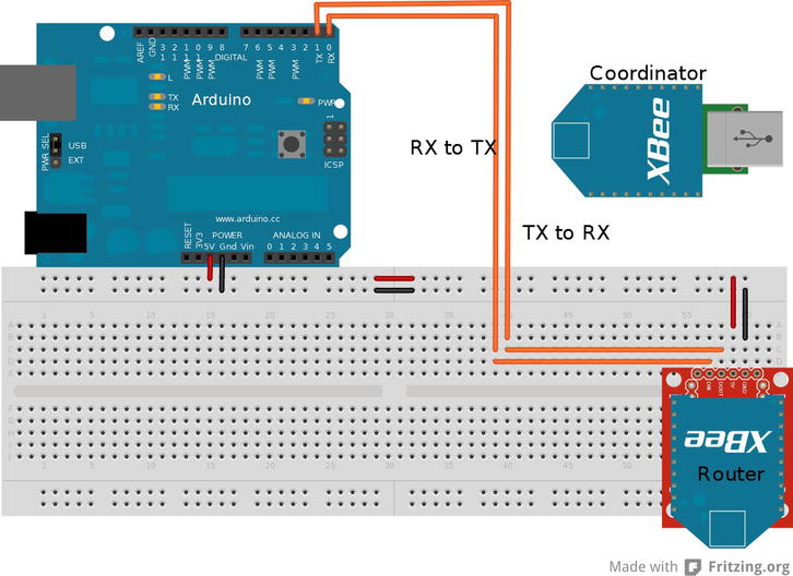
Figure 5-1. Arduino/XBee module configuration
The Firmata sketch is uploaded to the Arduino and the XBees are both plugged into the computer and Arduino. This configuration of the modules is in transparent mode, and the Firmata test app can now communicate with the Arduino. It is optional to add a few buttons, servos, or LEDs to explore the application’s potential, or use the examples created in Chapter 3. If the modules are not communicating, check the connections, settings, and selected COM port.
![]() Note You can make computer-to-computer chat possible with the XBee’s transparent mode and serial terminals by connecting the XBee serial adapter to pins 2 and 3 of the Arduino and loading the software serial sketch onto the Arduino, changing the baud rates in the sketch to match the XBee module.
Note You can make computer-to-computer chat possible with the XBee’s transparent mode and serial terminals by connecting the XBee serial adapter to pins 2 and 3 of the Arduino and loading the software serial sketch onto the Arduino, changing the baud rates in the sketch to match the XBee module.
API Mode
API mode is the alternative to AT command mode. The API that is implemented with the XBee module allows programs to change internal settings, create direct routing, discover new nodes, and push remote AT commands or firmware updates, along with other advanced control options. This mode uses packets that are referred to as frames in the XBee data sheet.
There are currently 18 different frame types for series 2 modules; the first 4 bytes of the frame are always the same type of information, as described in Figure 5-2.
- The first byte of the frame is always 0x7E to show that a frame is starting,
- The next two bytes are the length of the data contained in the frame; this number is the total bytes from the fourth byte to the checksum.
- Byte 4 is the frame type; this describes the data that makes up the data section of the frame, notifying a program how to interpret the data. The frame data is specific to the frame type. The structure is outlined for the various frames in the “API Operation” section of the XBee data sheet; the series 2 data sheet is available at http://ftp1.digi.com/support/documentation/90000976_K.pdf.
- The last byte of the frame is the checksum and is calculated by subtracting the total value of bytes from the frame type to the last byte of the frame data from 0xFF. This calculation is done within a single byte, and any value above 255 is truncated. The checksum is used by the modules to help determine that the frame is formed properly before sending and can be used by the program to determine that the data received is the proper data. The frame may be malformed when a verification frame is not returned or the when frame ID byte is set to zero. The frame ID is usually the first byte of the frame data section of the frame; this is to determine what frame is being talked about when information frames are returned. The frame ID is also useful for sequential frames to determine the order when receiving frames.
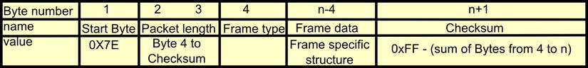
Figure 5-2. API packet structure
![]() Note Frames are what Digi’s data sheet calls the series of data that is used for API mode; the term frame is interchangeable with packet.
Note Frames are what Digi’s data sheet calls the series of data that is used for API mode; the term frame is interchangeable with packet.
Configuring the modules for API mode is similar to the setup for the AT command configuration:
- A single coordinator is needed. Change the firmware settings to ZIGBEE COORDINATOR API and ZIGBEE ROUTER API for the router.
- Set the PANID along with the baud rate; you can use the same settings as before for this setup.
- The destination address is not necessary for this mode to communicate; packets determine where the information is going.
- Choose a name for the node identification (NI) setting when configuring the module; ROUTER and COORDINATOR will suffice. The NI setting is helpful for identifying the node. This is independent of the addresses and equivalent to a computers host name.
- Upload the software serial sketch to an Arduino with both baud rates set to the XBee modules’ rate of 57600, and connect the serial adapter to pins 2 and 3 of the Arduino, as shown in Figure 5-3.

Figure 5-3 . Setup for API examples. The XBee is connected to pins 2 and 3 for software serial
- Once the Arduino is configured, connect via a serial terminal such as PuTTY, minicom, or HyperTerminal, with the setting 57600 8N1.
Before delving into writing code, I’ll describe the X-CTU software, which provides a utility on the Terminal tab to manually build packets. With the Arduino set up and the serial program running, “Goodnight moon!” should be printed the Arduino’s serial monitor, indicating everything is working. Plug the coordinator into the USB adapter, start the X-CTU software, double-check that the module can be accessed, and click the Terminal tab. On the Terminal tab is information on the line status and a few options. Click the Show Hex button to get a side-by-side ASCII-and-hex display, which will be a bit easier to read. Click the Assemble Packet button to bring up a window with an input box to place packet information; by default the input box is in ASCII mode, so make sure to select the Hex option so that the raw data can be entered.
The first packet you’re going to assemble is an AT command; this is equivalent to entering +++ ATND (followed by a carriage return) in transparent mode. The ND command is for network discovery and will return information on all XBees that can be accessed in the network; for example, the network ID, the 64-bit address, and the plain-text name (if you set that option in the configuration). Packets are ordered from left to right or top to bottom. You can lay out the general structure of the packet on a piece of paper: the first four bytes are essentially the header that contains the start, the length, and the frame type.
Two of the bytes are known and can be filled in: 0x7E for the start and 0x08 for the frame type of the AT command to be sent. The packet is not complete, so the length cannot be determined yet. The first byte after the header is the frame ID that identifies the packet and enables the response to the packet: this is going to be set to 0x01 because only this packet is going to be sent for this example.
The AT command comes after the frame ID and is the hex value of the two characters that describe the command; in this case N (0x4E) and D (0x44) for the node-discovery command. Following the AT command characters is the setting value used when changing the setting for this packet, No setting change is needed, so no more bytes are added to this packet. The last byte of the packet is the checksum, which is calculated using the bytes that make up the frame packet with the frame type byte, so add the following value:
0x08 +0x01+0x4E+0x44 = 0x9B
Then subtract this value from 0xFF to get the checksum value:
0xFF – 0x9B = 0x64
The last byte to calculate is the size, which is done by counting the bytes between the size and the checksum (or the bytes used to calculate the checksum); in this case the size is 4 bytes. The final packet looks like this:
0x7E 0x00 0x04 0x08 0x01 0x4E 0x44 0x64
With the packet manually calculated, enter the bytes into the packet-assembly window in the X-CTU software and send the data to the module connected to the computer. The node-discovery command sent will discover the other modules that can receive data from the coordinator. After the command was sent, a reply packet will be received that contains information on the nodes seen. The header of this packet will be 0x7E followed by the size and the frame type 0x88, indicating that it is a response to the AT command sent. Any received frame will be identified by the frame type, and can be compared to the packet type lists later on to help determine how to interpret the frame.
In the frame data, the first byte is the frame ID, which should match the frame ID originally sent, followed by the command being responded to (which should be ND) and the command status of 0x00, indicating that the command was successful. The rest of the data contained in packet includes the 16-bit network address, the 64-bit serial number, a space, the node identifier, the parent network address, the device type, the status, the profile ID, the manufacture ID, and the checksum. If the node-identifier variable was set on all the modules, their plain-text ID should be readable; in this example, the string ROUTER should be clear on the ASCII side of the terminal window.
There are two frame types that affect the local module:
- The AT command frame (0x08), which will immediately change values.
- The AT command queue (0x09), which holds changes until the apply-changes (AC) command has been issued or a subsequent AT command (0x08) is sent.
The ability to send AT commands to a remote module is a unique function that is not available in AT command mode. Sending remote AT commands uses a frame type of 0x17 and is constructed in a similar fashion as the local AT frame (0x08). There is extra data contained in the frame data section after the frame ID byte:
- First is the 64-bit destination address followed by the 16-bit network address. For the example following, (0x00 00 00 00 00 00 FF FF) will be used for the 64-bit and (0xFF FE) for 16-bit.
- The next byte is a command option; it has the same effect if set to 0x00 as the AT command queue and needs the AC command to finalize the changes. The other options for the command option byte are 0x02 to apply the changes immediately, 0x20 to use encryption if globally set in the EE register, and 0x40 to use a longer transmission timeout. Settings 0x00 and 0x02 are the only two of interest for this example.
- The AT command is after the command option byte; the node-discovery command will be used for this packet to see what the ROUTER module can transmit to.
The example packet is the following:
0x7E 0x00 0x0F 0x17 0x01 0x00 0x00 0x00 0x00 0x00 0x00 0xFF 0xFF 0xFF 0xFE 0x00 0x4E 0x44 0x5A
The example packet sends a request to all devices on the network, asking for those modules to perform a node discovery and send back their findings to the originating device. The return packet follows the same structure as any other packet, with the header, frame data, and checksum being in the same order. The returned packet’s frame data has the 64- and 16-bit network address of the remote module added between the frame ID and the command bytes. The frame data is identical in structure to the local command, excluding the added address bytes. The value for this frame type is 0x97.
The example remote AT command packet will execute on all the modules that can hear the coordinator. On large networks this can cause talk-over communication packet corruptions and is not advisable. In some situations broadcasting a change-setting packet is needed, as when changing the pan ID of the whole network or changing encryption settings. When changing settings across an entire network, change and apply the settings to the remote modules before changing the local module.
Up to this point, configuration packets have been constructed and sent, but no data has been sent through to the Arduino that is connected to the serial program. The packets for sending data are constructed in the same order as the AT command packets, with the frame IDs being 0x10 and 0x11.
- The 0x10 data packets are general-purpose data containers that leave the network routing up to the modules.
- In contrast, 0x11 packets have more options on how the packet should reach its destination.
Digi provides a web-based utility that makes the manual assembly of packets easy; it’s available at http://ftp1.digi.com/support/utilities/digi_apiframes.htm. The utility calculates the errorsum and the size bytes for any of the frame types, with a convenient layout of the byte field. To use this utility, select the frame ID to be constructed.
- For this example, select the request transmit (0x10), and use the broadcast address of 0x00 00 00 00 00 00 FF FF for the 64-bit address and 0xFF FE for the 16-bit address.
- Leave the other options as they are and add the hexadecimal equivalent of “HELLO” to the RF packet field (0x48 45 4C 4C 4F).
- The button next to the packet field will build the packet that needs to be entered into the packet assembly window of the X-CTU. The packet should appear as follows:
7E 00 13 10 01 00 00 00 00 00 00 FF FF FF FE 00 00 48 45 4C 4C 4F 7F
On the local module’s side, the return packet is of frame type 0x8B and contains the 16-bit destination address, the number of transmit retries, the delivery status, and the discovery status. If both broadcast addresses are used, the 16-bit network address will be 0xFF FE if the 64-bit address of the module was used in transmitting with the 0xFF FE network address. The returned packet will have discovered the actual network address of the remote module. The three bytes after the network address indicate status—if the values come back as zeros, then the transition succeeded for the example packet.
The Arduino that has the receiving XBee connected should have echoed the packet to the screen. The packet shows up in the serial program as the printable characters, making most of the packet unreadable, but the data section should be a clearly readable “HELLO.” The packet received that is echoed is the reply packet with frame type 0x90. This packet has no frame ID, the bytes after the frame type are the 64-bit and 16-bit addresses. The byte after the network address and before the data is a status byte; this byte provides the program with information that can be valuable when dealing with this packet. The status byte is a sum of four possible options:
- 0x01: Packet was acknowledged
- 0x02: Packet was acknowledged and is a broadcast
- 0x20: Packet is encrypted
- 0x40: Packet was sent from an end device
So, for example, if the byte is sent from an end device with a broadcast, the byte will have a value of 0x22.
The remaining bytes that complete the packet are the data and checksum.
Request Packets
Table 5-1 is a reference for the various packets that can be used to control the XBee modules. The frame name, the frame type, a general description, and the frame data are provided. Remember that the frame type is the last byte of the header, and following the frame data is the checksum.
Table 5-1. Packet Reference

Table 5-2 shows the packets that are usually formed in a response to another packet. They are created outside of the program that creates the packet. These packets contain information that needs to be phrased so that the program can use the information. These packets still follow the same general structure as the request packets.
.jpg)
.jpg)
With a bit of understanding of the formation and reading of packets, this example will demonstrate in code the phrasing, retransmission, and construction of packets the code receives. The code will run on the Arduino and take incoming data packets (0x90) from any module in the network and pull the data out to reassemble the packet and retransmit back to the original source.
While the packet gets transmitted to the source, the code will print relative data to a serial monitor, such as a notification when an incoming packet has been received, the raw packet itself, addresses of the originating source, and the raw reply packet for sending. The code currently identifies and displays two different packets types (0x90) and (0x8B). This is accomplished through a switch statement after the whole packet has been captured.
The switch statement is pretty effective and can be expanded to recognize and handle current packet types plus any future additions. The packets are received and constructed in a byte array of 80 bytes, which is done to buffer the packets and to help ensure they’re complete before any phrasing is done or transmission starts. Although the XBee modules are capable of sending packets of greater sizes, this limit is to save on some space on the Arduino.
The setup is the same as in Figure 5-3, previously. The code uses software serial at 9600 baud and standard serial at 57600 baud; the XBee modules have to be reconfigured to 9600 baud. There are two ways to reconfigure the baud settings:
- Use the X-CTU software to set the baud back to setting 3.
- Construct and issue two AT command packets: one for the remote module and the other for the local module. The AT command is BD or 0x42 44, with the parameter being 3.
Both require you to change the X-CTU COM setting back to 9600 to accommodate the new setting. This example is one-sided, so packets sent to the Arduino will still have to be constructed in the terminal of the X-CTU; the HELLO packet will work for this example, although any properly formed transmit request will work with this code. To finish the setup for this example, step through the code and upload it to the Arduino.
Listing 5-1 is comprised of three parts. The first part sets up the variables and all the initialization of the Arduino’s serial connections before entering the loop function. The loop functions waits for the software serial to be available and checks for the packet start byte of 0x7E. A loop captures the packet and counts the incoming bytes while the software serial is available. When the packet is received, the user is informed of the incoming packet along with the contents of the raw packet by printing the details to the serial monitor before processing the packet. The first part of packet processing is to calculate the checksum by calling a function. If the checksum is correct, the program continues with parsing the packet and constructing and sending a reply packet that contains the same data that the received packet contained.
Listing 5-1. Arduino Packet Echo Code, Part 1 of 3
#include <SoftwareSerial.h>
byte incomePacket[80];                               // buffer for incoming data
char incomeData [64];                                // phrased data holder
byte replyPacket[80];                                // packet construction buffer
byte sourceADR[10];                                  // source addresses
int datalen;                                         // length of data received
int count;                                           // total length of incoming packet
int length;                                          // misc. length holder
byte calcsum ;                                       // checksum
SoftwareSerial softSerial(2, 3);           // the main software serial

void setup()  {
   Serial.begin(57600);      // serial to monitor
   softSerial.begin(9600);   // serial to XBee
   Serial.println("Ready");
} // end setup

void loop(){
  if (softSerial.available() && 0x7E == softSerial.read() ){ // check for start byte
    incomePacket[0] = 0x7E;
    count = 1;
    while (softSerial.available()){
      incomePacket[count] =  softSerial.read();  // receive the incoming packet
      count ++;  // keep track of incoming bytes
    }  // end while (softSerial.available())
    Serial.println ("Recived a new packet");
    Serial.print ("Incoming packet is: ");
    for (int i = 0 ; i < count-1 ; i++){   // print raw packet
      Serial.print (incomePacket[i],HEX);
      Serial.print (' '),
    }
    Serial.println (incomePacket[count-1],HEX);   // last byte of the raw packet
    calcChecksum ();
    if (calcsum == incomePacket[count-1]){  // throw error if the checksum does not match
      processPacket();
    } // end if calcsum
    else {
      Serial.println ("Error packet is not proper");  // the error when packets are malformed
      while (softSerial.available()){
      softSerial.read();  // on error flush software serial buffer
      }
    }
  }// end looking for start byte
}// end loop
Part 2 of the program contains the functions to calculate the checksum and parse the packets’ data. The calcChecksum function pulls the length of the packet from the first two bytes after the packet start, and then the checksum is calculated before retuning back to the loop function. When the processPacket function is called, the user is informed that the packet has the correct checksum; the code then determines the packet type using the fourth position of the packet. The switch statement responds to a transmission-reply packet (0x8B) and a data-receive packet (0x90). The transmission-reply packet is handled by informing the user by printing to the serial monitor. The data packet is handled by parsing out the address of the sending XBee and pulling out the data to be used to construct a reply packet. During the whole process, the information is printed to the serial monitor.
Listing 5-1. Arduino Packet Echo Code, Part 2 of 3
void calcChecksum () {
  calcsum =0;     // begin calculating errorsum of incoming packet
  length = incomePacket[1] +incomePacket[2];
  for (int i = 3 ; i <= length+2 ; i++){
    calcsum = calcsum + incomePacket[i];
  }
  calcsum = 0xFF - calcsum;  // finish calculating errorsum
}     // end void calcChecksum ()

void processPacket(){
  Serial.println ("Packet has correct checksum ");
  switch (incomePacket[3]){  // check packet type and perform any responses
    case 0x90:
      Serial.println ("The packet is a data packet"); // announce packet type
      for (int i = 4 ; i <= 13 ; i++){  // get both addresses of the source device
        sourceADR[i-4]= incomePacket[i];
      }
      datalen = count - 16 ;  // reduce to just the data length to get the data
      for (int i = 15 ; i < datalen+15 ; i++){
        incomeData [i-15] = incomePacket[i]; // phrase out the data
      }
      Serial.print ("source addess is: ");  // begin printing 64 bit address
      for (int i =0 ; i < 7 ; i++){
        Serial.print (sourceADR[i],HEX);
        Serial.print (' '),
      }
      Serial.println (sourceADR[7],HEX); // finish 64-bit address
      Serial.print ("network addess is: "); // begin printing 16-bit address
      Serial.print(sourceADR[8] ,HEX);
      Serial.print (' '),
      Serial.println(sourceADR[9] ,HEX); // finish 64-bit address
      Serial.print ("the packet contains: ");  // start printing the data from packet
      for (int i =0 ; i < datalen ; i++){
        Serial.print (incomeData [i]);
      }
      Serial.println (" : For data");   // finish the data print
      constructReply();
      break; // done with the received packet
    case 0x8B: //start response to the return packet from sending data
      Serial.println ("Received reply ");
      break;
    default: // anouce unknown packet type
      Serial.println ("error: packet type not known");
  }// end switch
}    // end processPacket()
Part 3 of the code echoes the data received from another XBee. The reply packet is built one byte at a time in an array starting with the packet start frame, the type, and the frame ID. Portions of the packet that are a single-byte setting are set one at a time. The parts of the packet that are from the received packet are added to the outgoing packet via for loops (the parts added include the address to send the new packet to and a copy of the received data). When the packet is almost complete, the packet size is calculated and added. The final calculation to be added to the packet is for the checksum before the packet is sent, and the program continues waiting for new packets.
Listing 5-1. Arduino Packet Echo Code, Part 3 of 3
void constructReply(){
  Serial.println ("Constructing a reply packet"); // announce packet construction
  // start adding data to the reply packet buffer
  replyPacket[0] = 0x7E;    // start byte
  replyPacket[1] = 0; // 1st address byte will be zero with current limitations
  replyPacket[3] = 0x10;        // frame type
  replyPacket[4] =  1;         // frame ID
  for (int i =5 ; i <= 14 ; i++){     // add addresses
    replyPacket[i] = sourceADR[i-5] ;
  }
  replyPacket[15] = 0 ;          // set both options
  replyPacket[16] = 0 ;
  for (int i =17 ; i < datalen+17 ; i++){
    replyPacket[i] =  incomeData [i-17];  // add data to packet
  }
  replyPacket[2] = 14 + datalen ;      // set the lower length byte
  calcsum = 0; // start calculating errorsum
  replyPacket[17 + datalen] = 0;
  for (int i = 3 ; i <= replyPacket[2]+3 ; i++){
    calcsum = calcsum + replyPacket[i];
  }
  replyPacket[17 + datalen]= 0xFF - calcsum; // finish packet by adding checksum
  Serial.print ("The packet is: ");  // start printing raw packet before sending
  for (int i = 0 ; i < replyPacket[2]+3 ; i++){
    Serial.print (replyPacket[i],HEX);
    Serial.print (' '),
  }
  Serial.println (replyPacket[17 + datalen],HEX); // finish printing packet
  Serial.println ("Sending Packet");   // start sending packet to original source
  for (int i =0 ; i <= 17 + datalen ; i++){
    softSerial.write ( replyPacket[i]);
  }
} // end void constructReply()
With everything compiled and hooked up, a prepared packet can be sent from the X-CTU’s packet-assembly window. Watch the code’s actions in a serial monitor that is connected to the Arduino. The serial monitor should start printing information when a packet is received and proceed through the programmed responses. This code is a demonstration of packet handling and sometimes messes up on receive and transmit packets, because of the lack of more robust error correction.
To make the error checking a bit more robust, you can the check the reply packet against the created checksum for the new packet and re-create it before the packet is sent. Other error checking can be performed with flow control, timeouts, resends, and packet-acknowledgement communication. The transmit status frame type (0x8B) that is returned when a packet is sent does not indicate that the packet was successfully received by anything other than XBee modules. A microcontroller should form a reply packet to the state of a received packet if the incoming packets are from serial out from an XBee module. This method of packet handling is demonstrated in greater depth in Chapter 8.
If the code in Listing 5-1 does not respond, resend the packet a few times before checking the configurations. You can also issue an ND command to check the XBee radio connection. If the radios can see one another, double-check the serial connections on the Arduino and, if necessary, revert to the software serial, and then double-check the code.
The last firmware option is that of endpoint for both AT and API modes. They act similarly to any other module firmware by issuing and receiving data. However, unlike the router and coordinator, end devices do not route packets to other devices. End devices also have the capability to enter sleep mode because they do not store routing information. Sleep mode makes end devices the preferred choice when making remote sensors or controllers that need low power consumption.
There are three types of sleep configuration that are set via the sleep mode (SM) register:
- Setting a value of 1 in the SM register will put the module in hibernate mode. When XBee pin 9 is high, the module will not respond to any transmissions or requests, but will return from sleep.
- Setting the SM register to 4 is for cyclic sleep. In this mode, the endpoint module will still respond to incoming transmissions. When using API mode, the extended timeout option (0x40) needs to be set in the packet’s transmit options, giving the end device time to wake up and respond. The controlling program in this mode must wait till the Clear to Send (CTS) flow-control line is low.
- Setting the value to 5 works the same as 4, but allows a transition from low to high on XBee pin 9 to wake the module for transmission.
Endpoint modules have the capability to connect to either routers or coordinators. The code and setup for the last example will work for the end device.
- For this setup, reconfigure the router module with ZIGBEE END DEVICE API.
- Use the same settings to create a network, change the node identifier to ENDDEVICE, set the SM register to 4, and connect back to the Arduino.
- Reconstruct the HELLO packet with 0x40 in the options byte, and send this packet to watch the code work. In this configuration, when the end device receives a packet, it will be awake for a period of time to allow the module to transmit the outgoing packet.
The next example (see Listing 5-2) Arduino sketch uses sleep mode 5, demonstrating a method of allowing other modules in the network to wake and send data to the end device, while allowing the code to wake up the module to send data. The code examples use the setup in Figure 5-4; the only change to the Arduino connections is that an extra connection is added between the serial adapter and the Arduino, connecting XBee pin 9 to Arduino pin 9. Both modules need to be set with AT command mode firmware—ZIGBEE COODINATOR AT for one and ZIGBEE END DEVICE AT for the other. The modules need the destination addressed set to be able to communicate. When configuring the end device, set the SM register to 5, allowing the code and other external events wake up the module.
Listing 5-2. Arduino Dual-Direction Communication with Sleep Mode Communications
#include <SoftwareSerial.h>
SoftwareSerial mySerial(2, 3); //rx,tx
void setup()  {
  pinMode (9 , OUTPUT);
  Serial.begin(9600);
  Serial.println("Ready");
  mySerial.begin(9600);
} // end setup

void loop() {
  digitalWrite (9 , LOW);
  if (mySerial.available())
    Serial.write(mySerial.read());
  if (Serial.available()){
    digitalWrite (9 , HIGH);  // transition from LOW to HIGH to wake up module
    delay (2);
    digitalWrite (9 , LOW);
    delay (2);                      // delay to give the chip time to recognize the transition
    mySerial.write(Serial.read());
  } // end if (Serial.available())
}   // end loop

Figure 5-4. End-device configuration
The code is a simple chat-style program that can receive data from another XBee and transmit data itself. With everything configured and plugged in, start a serial program to monitor and send data from the Arduino; use the terminal in the X-CTU’s terminal for the coordinator. Any data typed into either terminal will show up on the other terminal. When typing in the terminal for the Arduino, the code does not echo the typed data back to the terminal; the local echo in the terminal would need to be set for you to see the typed characters. This setup is good when devices need to access or poll from the end device when power consumption is a concern.
Summary
This chapter demonstrated working with XBee modules in both AT command mode and API packet mode. There are a lot more configuration and communication options available, such as implementing encryption, working with other ZigBee-compatible devices, and using the other available pins for analog-to-digital sensors or controlling PWM. The XBee data sheet for the modules provides a wealth of information. This chapter did not discuss setting up a large network of XBees, but the concepts described are scalable.