
![]()
Arduino Test Suite
Whether you are creating projects, sketches, or examples, testing is a skill that you will need. When you are developing a product to share or sell, it is critical that both your hardware and software behave as expected. Having a test helps people learn about how your project works. The Arduino Test Suite provides a way to prove that your product is functioning correctly. Incorporating tests into a project helps highlight the fixes and improvements that you have made. Additionally, using the social coding principles we described in Chapter 2, users are encouraged to submit issues to http://github.com/arduino/tests, including test examples, to demonstrate problems and verify the resolution of those problems. The more confidence people have in your product, the better.
The Arduino Test Suite library allows you to create a standard test suite for your own software and the Arduino software. This library provides a simple, standard way to build these tests. Each test suite run provides output formatted in the Arduino test result format. This output can be parsed by continuous integration testing software, like Jenkins, which can be found at http://jenkins-ci.org/. These tests can be added to your project’s official list of automatic tests, which run every time code is changed in the project’s repository.
In this chapter, I will
- Go through the basic features of the Arduino Test Suite
- Show how the built-in tests can be used with a custom test shield
- Provide a basic procedure using the Arduino Test Suite to create a comprehensive test that tests your project and code libraries
- Provide an example of testing memory usage
- Show an example of how to test the Serial Peripheral Interface (SPI) library
You are encouraged to create your own tests and submit them as official tests. They way this occurs is that you would “fork” the project, and create a new tests or modify an existing test for the project in your own repository. Then send a pull request for the change to the Arduino Test project in GitHub. This process is described in detail described in Chapter 2. You can also file issues for the project that suggest changes and improvements.
Installing the Arduino Test Suite
The Arduino Test Suite is located on GitHub in the Arduino Tests project, at http://github.com/arduino/tests. You can download, install, or clone the code into your sketch library folder. In this case, since the Arduino Test Suite is an Arduino library, the code will be installed in your libraries folder.
You can download the library from the http://github.com/arduino.tests download link, or, if you have installed Git, as explained in Chapter 2, you can issue the following command from libraries directory:
git clone https://github.com/arduino/Tests ArduinoTestSuite
When you restart Arduino, the Arduino Test Suite will appear in the user-contributed libraries, as shown in Figure 13-1. All of the example tests are in a dedicated folder in the Tests library, and these can be loaded from the Examples drop-down list in the Arduino IDE.
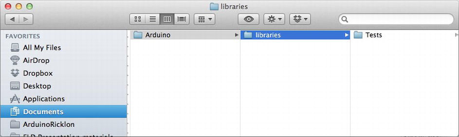
Figure 13-1. Arduino Test Suite installed in the sketch library folder
To verify that Arduino Test Suite is working, compile and upload the ATS_Constants example sketch to your hardware, as shown in Listing 13-1. On the serial monitor, you should see each result come back as OK. This indicates a successful test.
Listing 13-1. Arduino Test of Arduino Constants
#include        <ArduinoTestSuite.h>

//************************************************************************
void setup()
{
  Int           startMemoryUsage;

 //Start memory usage must be site prior to ATS_begin
  startMemoryUsage      =       ATS_GetFreeMemory();
  ATS_begin("Arduino", "Test of Arduino Constants");
  /*
   * Test Run Start
   */

  //test true constant
  ATS_PrintTestStatus("1. Test of true constant", true == 1);

  //test false consts
  ATS_PrintTestStatus( "2. Test of false constant", false == 0);

  //Test of HIGH == 1
  ATS_PrintTestStatus( "3. Test of HIGH == 1", HIGH == 1);

  //Test of LOW ==  0
  ATS_PrintTestStatus( "4. Test of LOW ==  0", LOW == 0);

  ???//Test of INPUT == 1
  ATS_PrintTestStatus( "5. Test of INPUT == 1", INPUT == 1);

  ???//Test of OUTPUT ==  0
  ATS_PrintTestStatus( "6. Test of OUTPUT ==  0", OUTPUT == 0);

  //test decimal
  ATS_PrintTestStatus( "7. Test of decimal constant", 101 == ((1 * pow(10,2)) + (0 * pow(10,1)) + 1));

  //test binary
  ATS_PrintTestStatus( "8. Test of binary constant", B101 == 5);

  //test octal
  ATS_PrintTestStatus( "9. Test of octal constant", 0101 == 65);

  //test hexadecimal
  ATS_PrintTestStatus( "7. Test of hexadecimal constant", (0x101 == 257));

  /*
  * Test Run End
   */
  ATS_ReportMemoryUsage(startMemoryUsage);
  ATS_end();

}

//************************************************************************
void loop()
{
}
Once the code is uploaded to the Arduino, you can connect to the serial port and view the test results. They should look like Figure 13-2.
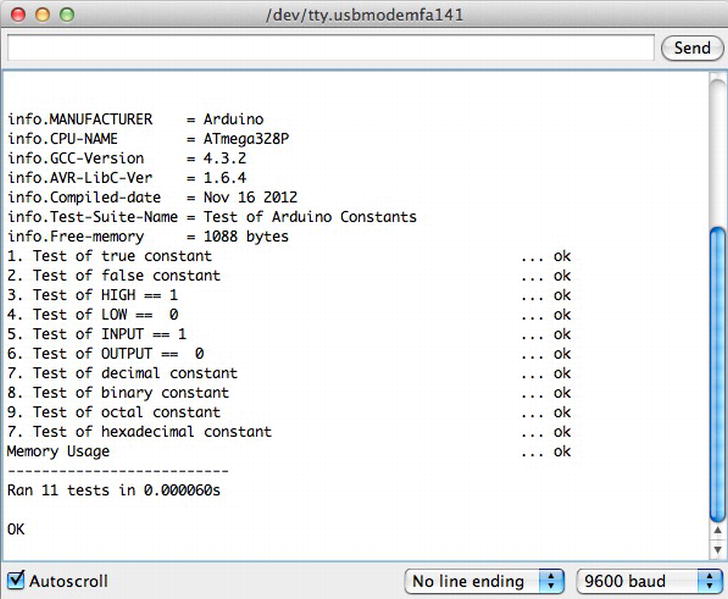
Figure 13-2. Arduino test results
Figure 13-2 shows the results of 11 tests, all which passed with an OK. If any of these tests fail, something is likely wrong with your Arduino environment, since the constants should always be defined. Now you are ready to run the example tests and create your own tests.
Getting Started with Testing
Testing Arduino helps to verify your hardware configuration and the logic of your software, and ensures that your Arduino-inspired board works exactly as expected. To begin, brainstorm the things that you want to test. Create a list and focus on one area at a time. It is effective to number the tests in your sketch and systematically work through each area. Each test you create should test one condition and verify the pass or fail result. In some cases, a function or a value is supposed to have false value as an expected result to be the success if the output is correct it’s considered a success.
Within the Arduino community, it is common to use examples instead of tests. Examples function similarly to tests, but while a test results in either pass or fail, an example allows you to compare what you thought would happen to what actually happens. There are many reasons for testing, including debugging code and observing the behavior of a remote control or line-following robot. Even more importantly, when we create libraries to share with others, we want to ensure that the code works and is easy for people to use. The goal of the Arduino Test Suite is to convert examples into official tests, which you can distribute with your libraries and sample codes, allowing others to learn from them. When someone files an issue against your code, they (or you) can add a test that shows where and how the problem was fixed.
The Arduino Test Suite comes with a test skeleton. This is the smallest test possible, which makes it a good starter sketch. This is shown in Listing 13-2.
Listing 13-2. Minimal Test Sketch
#include <ArduinoTestSuite.h>

//************************************************************************
void setup()
{
     ATS_begin("Arduino", "My bare bones tests");
     testTrue();
     ATS_end();
}
void testTrue()
{
     boolean result;
     result = true;
     ATS_PrintTestStatus("My bare bones test", result);
}
void loop()
{
}
Listing 13-2 shows the standard sketch structure. The tests are placed in setup(), so they are only run once. They can also be placed in loop(), which would run them multiple times; this can be useful if you are testing time and repetition issues. You can put your tests in loop() as long as you include while(1){} after the tests are complete.
In order to access the tests, you need to import the Arduino Test Suite with the #include <ArduinoTestSuite.h> line. Remember that tests need a name and an expected result. In this case, we create a Boolean variable called result. Our goal is to show that the result is TRUE. Here’s where we begin:
ATS_begin("Arduino", "My bare bones tests");
This sets up the test suite run and initializes the starting conditions. Then you can do anything you need to, including setting up variables, calling libraries, and calling any function that you are testing. The test result is set as an outcome of the code, and the status is printed to the serial port:
ATS_PrintTestStatus("My bare bones test", result);
Finally, once ATS_end() is called, the test is over and you can clean up.
An even better option for testing is to place each test in its own function. That way, it is more clearly isolated from other tests and side effects are largely avoided.
The results of the tests appear in the serial monitor format shown in Listing 13-3.
Listing 13-3. Minimal Test Sketch Results
info.MANUFACTURER    = Arduino
info.CPU-NAME        = ATmega328P
info.GCC-Version     = 4.3.2
info.AVR-LibC-Ver    = 1.6.4
info.Compiled-date   = Oct 20 2010
info.Test-Suite-Name = My bare bones tests
info.Free-memory     = 1464 bytes
My bare bones test                                          ... ok
--------------------------
Ran 1 tests in 1.371s

OK
The final OK shows that all tests passed and took a total time of 1.31 seconds. They passed because we created a result variable that held a true value, which was then passed to the ATS_PrintTestStatus() function. It has this function signature:
void ATS_PrintTestStatus(char *testString, boolean passed );
This char *testString is the test name, and boolean passed is the test result.
The Arduino test result format is based on the standard test format used by the Nose testing library from Python (https://nose.readthedocs.org/en/latest/). This format uses verbose mode so that all tests are listed with their outcomes. The output of the format is compatible with several different automated test systems. Since memory is limited and we want to preserve it for the tests as opposed to the testing library, this format is not based on an XML format. Each test must be discrete, and if one element fails, the incomplete XML file will be invalid and unusable. However, you can parse the output and change it to an xUnit test structure.
Another common use of the Arduino Test Suite is to use it to test the compiler toolchain to ensure that the compiler, and it’s support programs running your code properly. It is important for nonstandard compilers to check if an Arduino compiler upgrade is compatible with the Arduino API. The result format has a set of common data that allows you to know what toolchain your code is being compiled against. This is helpful because you can verify an upgraded GCC compiler or AVR-libc and be assured that your code functions, thanks to a passing test result. Another feature of the format is the ability to identify the manufacturer so you know what platform and microcontroller you are testing against. This way, you can test an entire family of Arduinos and clones and know that they are compatible with your code, libraries, or project. Each test has a date, time, and name, so you can keep track of the different tests.
Test Result Section Format Details
The test result file begins with information data. This is indicated by the info. at the beginning of the line, as shown in Listing 13-4.
Listing 13-4. Test Header Info Fields
info.MANUFACTURER    = Arduino
info.CPU-NAME        = ATmega328P
info.GCC-Version     = 4.3.2
info.AVR-LibC-Ver    = 1.6.4
info.Compiled-date   = Oct  4 2010
info.Test-Suite-Name = general
The header information section is followed by the test section, which includes the test results.
The test format is identical for all tests. This makes it easier for other software to parse them. The format includes the following items in the following order:
- The test name
- Information about the test (included in parentheses)
- Ellipsis points (i.e., ...)
- The test result status
The following line shows an example:
name of test(information about test) ...test result status
The tests themselves only have three valid outcomes: success, failure, or error:
ok
FAIL
ERROR
Test Summary
That last section of the test is a summary. It includes information such as how many tests were run, how long they took, and how many failures occurred. The test result summary is separated from the test by dashes, like so:
--------------------------
Here’s an example of the summary format, followed by final condition:
Ran n tests in Secs

OK
FAILED (failures=n)
The variable n is replaced by the correct number of tests, and the exact number of failures that occurred in the test run.
Arduino Test Suite Basic Functions
The following functions allow you to start, print, and end tests, respectively. I’ll describe them in detail in the following sections.
- ATS_begin ()
- ATS_end ()
- ATS_PrintTestStatus ()
This is the function signature for ATS_begin:
void ATS_begin(char *manufName,char *testSuiteName);
Here are some examples of its usage:
ATS_begin("Arduino","My test suite.");
ATS_begin("Teensy", "My test suite.");
ATS_begin("Adafruit Motor Shield", "My motor shield tests.");
These are all valid examples of beginning statements. You can set the manufacturer of the board or shield and test the suite name. The ATS_begin function initializes the serial interface so that you do not have to do this in your test sketches. Once the test starts, it keeps track of the time and other summary test information, such as number of failures.
You use the test status to return the test result to the user. Here is the syntax of the ATS_PrintTestStatus function:
void ATS_PrintTestStatus(char *testString,boolean passed);
And here are some examples of its usage:
ATS_PrintTestStatus("1. Test result is TRUE test" , true);
ATS_PrintTestStatus("2. Test result is FALSE test (a false result is expected)" , false);
In the function, the argument test name is followed by a Boolean test result (true or false). All tests must pass or fail. You can use a parentheses section to add a note about the test to clarify detail, if necessary. In the FALSE test case, we must say that failure is expected, since we want to see the failure case. This is an unusual case so it’s important to note it because interpreting the result could cause confusion.
Numbering is not automatic, so if you want to number your tests, put the numbering in the test name, like so:
ATS_PrintTestsStatus("1. my numbered test" , status);
ATS_end completes the test run. Test time and the final count of successful and failed tests are sent in the summary format to the serial port.
void ATS_end();
Using the Basic Functions
With these functions, you can create custom test suites and verify your code or project. The code in Listing 13-5 is an example that forces a result to be TRUE or FALSE. It is important to keep track of all test results, but especially failure conditions. This way at a glance the test issue can be found quickly. The failure condition can be described in the test name, and the result would be TRUE, which will appear as OK in the result.
Listing 13-5. Bare-Bones Test Sketch
#include <ArduinoTestSuite.h>

//************************************************************************
void setup()
{
     boolean result;
     ATS_begin("Arduino", "My bare bones tests");
     result = true;
     ATS_PrintTestStatus("My bare bones test", result);
     result = false;
     ATS_PrintTestStatus("1. My bare bones test", result);
     ATS_end();
}

void loop()
{
}
Here is the test result:
info.MANUFACTURER = Arduino
info.CPU-NAME = ATmega328P
info.GCC-Version = 4.3.2
info.AVR-LibC-Ver = 1.6.4
info.Compiled-date = Oct 20 2010
info.Test-Suite-Name = My bare bones tests
info.Free-memory = 1442 bytes
My bare bones test                             ... ok
1. My bare bones test                          ... FAIL
--------------------------
Ran 2 tests in 1.443s

FAILED (failures=1)
Once the test is complete, you will be able to see how many test were run, how long the tests took, and how many failures occurred. You can examine the tests to identify what happened. Additionally, you will get information about how much memory was available when you ran the tests. In this case, info.Free-memory shows that 1442 bytes were free in this test run.
Arduino Test Suite Built-In Tests
The Arduino Test Suite contains several built-in tests. These are very useful, as they standardize some of the basic tests. Running these standard tests will help you confirm that a custom Arduino-derived board has the correct pin numbers and behaves appropriately with the digital, analog, and PWM pins as the serial values are transmitted and received. You will need to test for memory leaks or heap fragmentation if things go wrong. The built-in tests are as follow:
ATS_ReportMemoryUsage(int _memoryUsageAtStart)
ATS_Test_DigitalPin(uint8_t digitalPinToTest)
ATS_Test_PWM_Pin(uint8_t digitalPinToTest)
ATS_Test_AnalogInput(uint8_t analogPintoTest)
ATS_Test_EEPROM(void)
ATS_TestSerialLoopback(HardwareSerial *theSerialPort, char *serialPortName)
For the Serial port test the RX/TX pins to be wired to one another. This loops the input and output of serial information into each other for reading, and parsing by the test suite. However, the test results are delivered over the first serial port, and the board is programmed through it. Therefore, you can’t test the port using this technique on the Arduino Uno, the Arduino Mega has multiple serial so there is extra serial ports that can be tested so you can still get the test results from the default serial.
Since these tests make the assumption that the board is wired for testing, you need to make sure your version of Arduino matches the wiring in Figure 13-3 or 13-4.
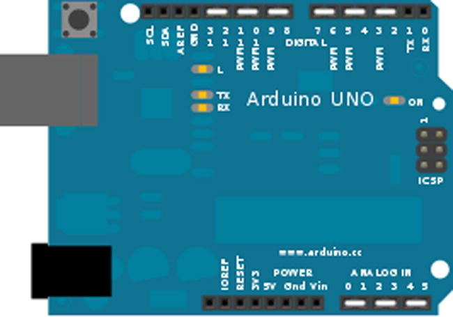
Figure 13-3. Arduino Uno configured for testing
You would use the design in Figure 13-4 to test a board similar to the Arduino Mega.
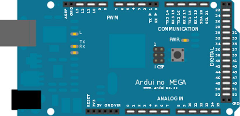
Figure 13-4. Arduino Mega test wiring
Strategies for Testing Your Own Arduino Derivative
The Arduino Test Suite contains all the necessary tests to verify that your board is fully functional. For creating a custom board to be compatible with the Arduino Uno or Mega pin layout, the Arduino Test Suite contains the ATS_General test. This test checks all the features of these two boards, including digital pins, PWM, analog read/write, EEPROM, tone, and serial RX/TX. If your custom board can pass these tests, then the board is pin-for-pin and feature compatible. You can save time and money by identifying problems early.
The ATS_General test requires that you wire the pins in a specific way. The digital I/O pins are tied together, the analog read/write pins are tied together, and serial RX/TX pins can also be tied together. For a board with only one serial port, you will want to skip the RX/TX test. This is detected in the current ATS_General test.
You would use the same wiring options like we’ve done with the Arduino Uno board in Figure 13-3. You would be configured for testing. You can do something similar for your own board.
The Arduino Test Suite provides a test for checking the amount of free memory available. This function is particularly useful for checking how much memory is being consumed and if it is being returned after use. You can find out how to use this function by studying the tests. This section will look at a subset of these tests and then demonstrate using this function to track memory usage and create a test that involves memory use. Listing 13-6 shows the code that we will examine. The complete test is part of the ATS examples. We will look at three tests:
- testAllocatingThenDeallocatingPreservesFreeMemory();
- testAllocatingAndDeallocatingSmallerPreservesFreeMemory();
- testRepeatedlyAllocatingAndDeallocatingMemoryPreservesFreeMemory();
Listing 13-6. ATS_GetFreeMemory Tests Example, from Matthew Murdoch
#include <ArduinoTestSuite.h>

void setup() {
  ATS_begin("Arduino", "ATS_GetFreeMemory() Tests");

  testAllocatingThenDeallocatingPreservesFreeMemory();
  testRepeatedlyAllocatingAndDeallocatingMemoryPreservesFreeMemory();

  testAllocatingAndDeallocatingSmallerPreservesFreeMemory();

  ATS_end();
}

// This test checks that the free list is taken into account when free memory is calculated
// when using versions of free() which *don't* reset __brkval (such as in avr-libc 1.6.4)
void testAllocatingThenDeallocatingPreservesFreeMemory() {
  int startMemory = ATS_GetFreeMemory();

  void* buffer = malloc(10);
  free(buffer);

  ATS_PrintTestStatus("Allocating then deallocating preserves free memory", startMemory ==   ATS_GetFreeMemory());
}

// This test checks that the free list is taken into account when free memory is calculated
// even when using versions of free() which *do* reset __brkval (such as in avr-libc 1.7.1)
void testAllocatingAndDeallocatingInterleavedPreservesFreeMemory() {
  void* buffer1 = malloc(10);
  int startMemory = ATS_GetFreeMemory();

  void* buffer2 = malloc(10);
  free(buffer1);

  ATS_PrintTestStatus("Interleaved allocation and deallocation preserves free memory",   startMemory == ATS_GetFreeMemory());

  free(buffer2);
}

void testRepeatedlyAllocatingAndDeallocatingMemoryPreservesFreeMemory() {
  int startMemory = ATS_GetFreeMemory();

  for (int i = 0; i < 10; i++) {
    void* buffer1 = malloc(10);
    void* buffer2 = malloc(10);
    void* buffer3 = malloc(10);
    free(buffer3);
    free(buffer2);
    free(buffer1);
  }

  ATS_PrintTestStatus("Repeated allocation and deallocation preserves free memory",   startMemory == ATS_GetFreeMemory());
}

// TODO MM Currently fails as __brkval is not increased, but the size of the free list is...
// Therefore looks as if the total amount of free memory increases (i.e. negative memory leak)!
void testReallocatingSmallerPreservesFreeMemory() {
  int startMemory = ATS_GetFreeMemory();

  // Allocate one byte more than the space taken up by a free list node
  void* buffer = malloc(5);
  buffer = realloc(buffer, 1);
  free(buffer);

  ATS_PrintTestStatus("Reallocating smaller preserves free memory",   startMemory == ATS_GetFreeMemory());
}

void testReallocatingLargerPreservesFreeMemory() {
  int startMemory = ATS_GetFreeMemory();

  void* buffer = malloc(1);
  buffer = realloc(buffer, 5);
  free(buffer);

  ATS_PrintTestStatus("Reallocating larger preserves free memory",   startMemory == ATS_GetFreeMemory());
}

void testAllocatingAndDeallocatingSmallerPreservesFreeMemory() {
  int startMemory = ATS_GetFreeMemory();

  // Allocate one byte more than the space taken up by a free list node
  void* buffer = malloc(5);
  free(buffer);
  buffer = malloc(1);
  free(buffer);

  ATS_PrintTestStatus("Allocating and deallocating smaller preserves free memory",   startMemory == ATS_GetFreeMemory());
}

void testReallocatingRepeatedlyLargerPreservesFreeMemory() {
  int startMemory = ATS_GetFreeMemory();

  void* buffer = malloc(2);
  for (int i = 4; i <= 8; i+=2) {
    buffer = realloc(buffer, i);
  }
  free(buffer);

  ATS_PrintTestStatus("Reallocating repeatedly larger preserves free memory",   startMemory == ATS_GetFreeMemory());
}

void loop() {
}
Example: Testing for a Memory Leak
Any new values created inside the memory test will use memory. So, you must declare all the variables that consume memory at the beginning of the setup.
startMemoryUsage = ATS_GetFreeMemory();
Once this is done, your starting memory is set. Anything that takes without putting back will be counted as a failure. The memory test is over when you call the following:
ATS_ReportMemoryUsage(startMemoryUsage);
Here are some hints for debugging:
- By putting the memory test at the bottom of the code, you can gradually move it higher into the code and see where the memory was lost.
- An OK indicates that the memory loss occurred below the memory test.
- A binary search will help you find the problem.
Listing 13-7 is a sketch of the testing skeleton.
Listing 13-7. Sketch of the Testing Skeleton
#include <ArduinoTestSuite.h>

//************************************************************************
void setup()
{
    int startMemoryUsage;

    //startMemoryUsage must be set directly before ATS_begin
    startMemoryUsage = ATS_GetFreeMemory();
    ATS_begin("Arduino", "Skeleton Test");
    /*
     * Test Run Start
     * Test one passes because result is set to true
     * Test two fails becuase result is set to false
     * You can test memory for any set of tests by using the ATS_ReportMemoryUsage test
     * There is also a way to print current memeory for debugging
     */
    ATS_PrintTestStatus("1. Test of true test status", true);
    ATS_PrintTestStatus("2. Test of false test status, this will fail.", false);
    ATS_ReportMemoryUsage(startMemoryUsage);
    /*
     * Test Run End
     */
    ATS_end();
}
//************************************************************************
void loop()
{
}
Here is the test result:
info.MANUFACTURER = Arduino
info.CPU-NAME = ATmega328P
info.GCC-Version = 4.3.2
info.AVR-LibC-Ver = 1.6.4
info.Compiled-date = Oct 20 2010
info.Test-Suite-Name = Skeleton Test
info.Free-memory = 1322 bytes
1. Test of true test status                         ... ok
2. Test of false test status, this will fail.       ... FAIL
Memory Usage ... ok
--------------------------
Ran 3 tests in 1.508s

FAILED (failures=1)
Testing Libraries
One of goals of this chapter is to make it possible to test your own libraries. In this section, we will test an Arduino library, which can be used as a model for testing your own. We’ll test the SPI library, which is used to communicate digitally with other electronic devices, such as temperature sensors, SD cards, and EEPROM, all of which all support the SPI protocol. To test the SPI protocol of Arduino, we can make two Arduinos talk to each other. We will connect them as a master-and-slave device.
The tests will be from the point of view of the master and ensure that the functions defined in the library work correctly. The tests will be part of the sketch that we load onto the master Arduino. The slave Arduino will be loaded with a sketch that configures it in slave mode and provides a set of information that will return known data to the master.
Figure 13-5 shows the two Arduinos configured in master-and-slave configuration. Pins 10, 11, 12, and 13 are tied together between them. Power and ground are connected so that the slave Arduino is powered by the master.

Figure 13-5. Arduino SPI master-slave wiring
We will use the Arduino SPI master test sketch and an Arduino SPI slave sketch, which will process the commands, expected returns, and values from the master, and confirm that an action occurred properly. Listing 13-8 shows the configuration of the slave SPI Arduino.
Listing 13-8. SPI_Slave_test.ino
/*
* SPI Slave test program
 * by Rick Anderson
 *
 * Set the defaults:
 * MSBFIRST
 * DataMode = SPI_MODE0;
 * Clock divider = SPI_CLOCK_DIV4,
 */

#include <SPI.h>

const byte TESTBYTE = 0b11110000;

void setup()
{
  Serial.begin(9600);
  //Slave out needs to be enabled by placing the MISO as OUTPUT
  pinMode(MISO, OUTPUT);

  //Use the AVR Code to turn on slave mode
  SPCR |= _BV(SPE);

  //Standard Arduino settings for SPI
  SPI.setBitOrder(MSBFIRST);
  SPI.setDataMode(SPI_MODE0);
  SPI.setClockDivider(SPI_CLOCK_DIV4);

  //Turn on interrupts for SPI
  SPI.attachInterrupt();
  Serial.println("Slave Configured");

}

/*AVR SPI interrupt callback
*Process commands sent to slave
* First transfer is the command value
* Second command pushes the value to the master
*/
ISR (SPI_STC_vect)
{
  const byte cc = TESTBYTE;
  if (SPDR == 0x00) //Only command is 0x00
  {
    SPDR = 0b11110000; // read byte from SPI Data Register
  }
  else
  {
    SPDR = 0b11111111; //Any other command returns 0xff
  }
}

void loop()
{
  Serial.println("SPI Slave Sketch for testing SPI Master.");
  if (digitalRead (SS) == HIGH)
  {
    SPDR = 0;//When not enable set buffer to 0
  }
}
This kind of test requires an Arduino to be configured in slave mode. In order to get the slave to be in SPI slave mode, you must use AVR code. SPCR |= _BV(SPE); enables slave mode for AVR SPI. Additionally, the SPI interrupt needs to be enabled. It is worth noting that you can use the Arduino SPI.attachInterupt() or call the AVR code directly. In Listing 13-9, you can see that all the function does is call the AVR code.
Listing 13-9. SPI.h attachInterrupt Code
void SPIClass::attachInterrupt() {
  SPCR |= _BV(SPIE);
}
Once the interruptions are turned on, you must write the callback function that will run once the SPI interrupt is triggered. This function is
ISR (SPI_STC_vect) {}
Each function of the SPI library, as well as part of the master Arduino sketch, will need to be tested. The SPI library has defined the following functions:
- begin ()
- end ()
- setBitOrder ()
- setClockDivider ()
- setDataMode ()
- transfer ()
The begin() function instantiates the SPI object. This test will instantiate SPI and determine if the SPI object was created by setting the pin modes for the SPI lines and configuring the hardware SPI feature in master mode.
The end() function disables the SPI configuration using the following AVR code:
SPCR &= ∼_BV(SPE);
This leaves the pin modes as they were: INPUT and OUTPUT.
Given the functions in the SPI library, we can now test them in use. Listing 13-10 is the SPI master test code. The online version provides the full test, https://github.com/ProArd/SPI_Master_test. We will look at a few of the key test cases and examine how they work.
Listing 13-10. SPI_Master_test.ino
#include <ArduinoTestSuite.h>
#include <SPI.h>

void setup ()
{
  // Serial.begin(9600);
  ATS_begin("Arduino", "SPI Tests");
  SPI.begin();
  //Run tests
  refConfig();

  testTransfer();
  refConfig();

  testBitOrderMSB();
  refConfig();

  testBitOrderLSB();

  testDataMode();
  refConfig();

  testClockDivider();

  SPI.end();
  ATS_end();
}

void refConfig()
{
  SPI.setBitOrder(MSBFIRST);
  SPI.setDataMode(SPI_MODE0);
  SPI.setClockDivider(SPI_CLOCK_DIV4);
}
byte SPITransfer(byte val, uint8_t spi_bitorder, uint8_t spi_mode, uint8_t spi_clockdivider)
{
  byte spireturn;
  SPI.setBitOrder(spi_bitorder);
  SPI.setDataMode(spi_mode);
  SPI.setClockDivider(spi_clockdivider);
  digitalWrite(SS, LOW);
  spireturn = SPI.transfer(val);
  delayMicroseconds (10);
  spireturn = SPI.transfer(0x00);
  digitalWrite(SS, HIGH);
  return spireturn;
}

void testTransfer()
{
  boolean result = false;
  byte spireturn;

  spireturn = SPITransfer(0x00, MSBFIRST, SPI_MODE0, SPI_CLOCK_DIV4);

  if (spireturn == 0xf0)
  {
    result = true;
  }
  ATS_PrintTestStatus("1. transfer(0x00)", result);
}

void testBitOrderMSB()
{
  //Sets the bit order to MSBFRIST expects byte 0xf0
  boolean result = false;
  byte spireturn;

  spireturn = SPITransfer(0x00, MSBFIRST, SPI_MODE0, SPI_CLOCK_DIV4);
  if (spireturn == 0xf0)
  {
    result = true;
  }
  ATS_PrintTestStatus("2. setBitOrder(MSBFIRST)", result);
}

void testBitOrderLSB()
{
  //Sets the bit order to LSBFRIST expects byte 0xf
  boolean result = false;
  byte spireturn;

  spireturn = SPITransfer(0x00, LSBFIRST, SPI_MODE0, SPI_CLOCK_DIV4);
  if (spireturn == 0xf)
  {
    result = true;
  }
  ATS_PrintTestStatus("3. setBitOrder(LSBFIRST)", result);
}

void testDataMode()
{
  //asserting the default mode is true
  boolean result = false;
  byte spireturn;

  spireturn = SPITransfer(0x00, MSBFIRST, SPI_MODE0, SPI_CLOCK_DIV4);
  if (spireturn == 0xf0)
  {
    result = true;
  }
  ATS_PrintTestStatus("4. setDataMode(SPI_MODE0)", result);

  result = false;
  spireturn = SPITransfer(0x00, MSBFIRST, SPI_MODE1, SPI_CLOCK_DIV4);
  if (spireturn == 0xf0)
  {
    result = true;
  }
  ATS_PrintTestStatus("5. setDataMode(SPI_MODE1) should fail so reports ok", !result);

  result = false;
  spireturn = SPITransfer(0x00, MSBFIRST, SPI_MODE2, SPI_CLOCK_DIV4);
  if (spireturn == 0xf0)
  {
    result = true;
  }
  ATS_PrintTestStatus("6. setDataMode(SPI_MODE2) should fail so reports ok", !result);

  result = false;
  spireturn = SPITransfer(0x00, MSBFIRST, SPI_MODE3, SPI_CLOCK_DIV4);
  if (spireturn == 0xf0)
  {
    result = true;
  }
  ATS_PrintTestStatus("7. setDataMode(SPI_MODE3) should fail so reports ok", !result);
}

void testClockDivider()
{
  //asserting the default mode is true
  boolean result = false;
  byte spireturn;

  spireturn = SPITransfer(0x00, MSBFIRST, SPI_MODE0, SPI_CLOCK_DIV2);
  //Slave is CLOCK_DIV4 so this should fail
  if (spireturn == 0xf0)
  {
    result = true;
  }

  ATS_PrintTestStatus("8. setClockDivider(SPI_CLOCK_DIV2) should fail so reports ok", !result);
  result = false;

  spireturn = SPITransfer(0x00, MSBFIRST, SPI_MODE0, SPI_CLOCK_DIV4);
  if (spireturn == 0xf0)
  {
    result = true;
  }
  ATS_PrintTestStatus("9. setClockDivider(SPI_CLOCK_DIV4)", result);
  result = false;

  spireturn = SPITransfer(0x00, MSBFIRST, SPI_MODE0, SPI_CLOCK_DIV8);
  if (spireturn == 0xf0)
  {
    result = true;
  }
  ATS_PrintTestStatus("10. setClockDivider(SPI_CLOCK_DIV8)", result);
  result = false;

  spireturn = SPITransfer(0x00, MSBFIRST, SPI_MODE0, SPI_CLOCK_DIV16);
  if (spireturn == 0xf0)
  {
    result = true;
  }
  ATS_PrintTestStatus("11. setClockDivider(SPI_CLOCK_DIV16)", result);
  result = false;

  spireturn = SPITransfer(0x00, MSBFIRST, SPI_MODE0, SPI_CLOCK_DIV32);
  if (spireturn == 0xf0)
  {
    result = true;
  }
  ATS_PrintTestStatus("12. setClockDivider(SPI_CLOCK_DIV32)", result);
  result = false;

  spireturn = SPITransfer(0x00, MSBFIRST, SPI_MODE0, SPI_CLOCK_DIV64);
  if (spireturn == 0xf0)
  {
    result = true;
  }
  ATS_PrintTestStatus("13. setClockDivider(SPI_CLOCK_DIV64)", result);
  result = false;

  spireturn = SPITransfer(0x00, MSBFIRST, SPI_MODE0, SPI_CLOCK_DIV128);
  if (spireturn == 0xf0)
  {
    result = true;
  }
  ATS_PrintTestStatus("14. setClockDivider(SPI_CLOCK_DIV128)", result);
  result = false;
}

void loop (){}
SPI.transfer() is the main function of this library. In the past, we’ve used it to verify that data was sent properly between various configurations. Now we want to test if it sends data as defined in the API. A byte should be sent to the slave device, and a byte will be received as the return value from the slave device, as shown in Listing 13-11.
Listing 13-11. Data Transfer Test
void testTransfer()
{
  boolean result = false;
  byte spireturn;

  spireturn = SPITransfer(0x00, MSBFIRST, SPI_MODE0, SPI_CLOCK_DIV4);

  if (spireturn == 0xf0)
  {
    result = true;
  }
  ATS_PrintTestStatus("1. transfer(0x00)", result);
}
The bit order of the device must be matched by the Arduino communicating with it. There are two supported configurations:
- Least significant bit (LSB)
- Most significant bit (MSB)
For the first test, the slave Arduino must be configured for LSB, and for the second test, the slave Arduino needs to be configured to MSB, as shown in Listing 13-12.
Listing 13-12. setBitOrder MSB Test
void testBitOrderMSB()
{
  //Sets the bit order to MSBFRIST expects byte 0xf0
  boolean result = false;
  byte spireturn;

  spireturn = SPITransfer(0x00, MSBFIRST, SPI_MODE0, SPI_CLOCK_DIV4);
  if (spireturn == 0xf0)
  {
    result = true;
  }
  ATS_PrintTestStatus("2. setBitOrder: MSBFIRST", result);
}
The clock divider changes the SPI speed to be a multiple of the Arduino clock speed. This way, it is possible to change the speed of the SPI bus to match that of the attached device. For this test, we need to set the clock divider at each of its multiples and ask the attached Arduino for a piece of data that matches the clock speed, as shown in Listing 13-13.
Listing 13-13. setClockDivider Test for SPI_CLOCK_DIV2
void testClockDivider()
{
boolean result = false;
 byte spireturn;
  //SPI_MODE0 test 3
  setSlaveClockDivider(SPI_CLOCK_DIV2);
  SPI.setClockDivider(SPI_CLOCK_DIV2);

  spireturn = SPI.transfer(0x02);
  if (spireturn > 0)
  {
    result = true;
  }
  ATS_PrintTestStatus("4. setClockDivider:SPI_CLOCK_DIV2 (failure is OK)", result);
}
The test in Listing 13-13 is a testing condition for when the clock divider is set to twice the speed of the slave device. This type of test is expected to fail. The code is written to discover the failure and report a completed test. A true result is reported as a pass. The parentheses are used to indicate that the test is OK even though failure was expected.
The data mode configures the clock phase and the polarity. For this to be tested, each mode must be set, and the slave Arduino must send a piece of data that shows that it was received and returned properly, as shown in Listing 13-14.
Listing 13-14. SetDataMode Test for SPI_MODE0
void testDataMode()
{
boolean result = false;
 byte spireturn;
  //SPI_MODE0 test 3
  setSlaveDataMode(SPI_MODE0);
  SPI.setDataMode(SPI_MODE0);
  spireturn = SPI.transfer(0x02);
  if (spireturn > 0)
  {
    result = true;
  }
  ATS_PrintTestStatus("3. setDataMode: SPI_MODE0", result);
}
The test in Listing 13-14 will return a TRUE result if you can communicate with the slave device in that mode. If a configuration or communication error occurs, it will fail.
SPI Test Results
In conclusion, the complete set of test runs shows that the expected configuration of the master and slave match. The commands that are issued must be valid configurations of SPI in order to work correctly. If we change the slave configuration, we have to change the master test, or else we will see expected failures due to mismatched configurations.
There are many test cases within each of these variations. The full source for this on the Pro Arduino SPGitHub repository, http://github.com/proardwebsite goes through many more test cases, each with a single change from the last one. Another good challenge for SPI testing would be to reconfigure the slave device to iterate through each of its configurations. Creating these tests proves that SPI is working and simultaneously gives you a chance to learn how SPI works.
Summary
This chapter describes the features and benefits of the Arduino Test Suite. The goal is to show how to move from creating examples that demonstrate your code to creating a test that verifies it. Not only is this good for code quality, but it allows you to make custom circuits, shields, and your own verified Arduino-inspired device. As you share your code and hardware with others, testing provides usage examples and behavior confirmation.
The challenge of creating testable conditions is not simple. The environment of the project must be included, and users are encouraged to submit their tests to the Arduino testing project on GitHub. This ensures that the entire platform is well tested and documented, and provides a high-quality user experience.