
![]()
Simulating Sensors
Arduinos can be used to simulate sensors for Arduinos or other platforms that use sensors. Simulating sensors allows you to produce repeatable and known data that can be used to test and debug systems, as well as explore sensors that may not be available. The concepts in this chapter focus on the connection types of various sensors instead of the data sent. Although the data is purposely skewed, it is being sent via the same methods used by the actual sensors.To better demonstrate that Arduinos can directly simulate the various sensors, reader code for each type of interface is included with the examples; this code is unmodified sensor reader code available from various sources.
These concepts are not designed to replace sensors, and may take more time to get working than using the actual sensor for small projects. The techniques of sensor simulation become useful for applications that require controlled data manipulation, such as robotic development, testing platforms, and studying how a sensor works. Ultimately, this chapter aims to help you get over some of the speed bumps you’ll encounter when developing systems to simulate sensors or creating more complex sensor packages.
Sensors convert various physical changes to electrical data, which can then be read by computer systems. Temperature, position, and chemical concentrations are examples of physical elements that can be measured by sensors. When emulating sensors, it is not important to simulate the entire workings or the complete functionality; however, the data needs to be sent at the same time, in the same order, and with the same method as the sensor being simulated. Data sheets provide the necessary information for a sensor’s important functions (e.g., data range, communication types, and data types). The hardware requirements for this chapter are two Arduino-compatible boards based on the ATmega 328P and a good assortment of general prototyping components. One Arduino is to be used as the sensor reader and the other is to simulate a sensor. Using two boards will accommodate a wide range of sensors and allows the sensor sketch to remain separate from the reader’s sketch. This allows for the most accurate simulation in terms of program timing, and when the simulated sensor is replaced with a functional sensor, it requires no modification of the sketch on the reader side.
Analog Sensors
There are a variety of analog sensors that can measure temperature, movement, or position, for example. These types of sensors continuously control the output voltage, which is directly correlated with the state of the sensor. The output information can then be read by the Arduino when the analog pins are accessed. You could mimic the analog data with a potentiometer, but since a potentiometer is a sensor type itself, it is not effective for automated control.
The Arduino has analog inputs but no true analog out. There are methods to remedy the lack of analog output with a digital-to-analog converter (DAC) or a digital potentiometer, which are great for full production systems, but they are rarely found in the average collection of components. The examples in this section demonstrate how to make two different DACs using only resistors and capacitors to produce analog signals. The first example is focused on an Analog Devices TMP35 temperature sensor code for the Arduino.
Analog Sensor Reader
Listing 6-1 is the reader code for both analog sensor examples. This code should be loaded onto the Arduino that is to be used as the sensor reader; the other Arduino will be used as the sensor that provides the analog signal. The way the code works for Listing 6-1 has not been changed from the original online example from the LadyADA web site (located at www.ladyada.net/learn/sensors/tmp36.html), although the comments have been reworked. The example is for a temperature sensor, but the concept of reading the analog pin and then correlating the math with the sensor’s output works for other analog-type sensors. Listing 6-1 reads analog pin 0 and prints the data converted to temperature to the serial monitor.
Listing 6-1. LadyADA Temperature Sensor Reader Codewith Reworked Comments
int sensorPin = 0;

void setup() {
  Serial.begin(9600);
} // end void setup()

void loop()
{
 int reading = analogRead(sensorPin);
 float voltage = reading * 5.0; // covert reading to voltage
 voltage /= 1024.0; // divide the income voltage by max resolution of the ADC
 Serial.print(voltage); Serial.println(" volts");
 float temperatureC = (voltage - 0.5) * 100 ; // reduce by 500mV and mutiply
                                              // 100 to get degrees Celcius
 Serial.print(temperatureC); Serial.println(" degrees C");
 float temperatureF = (temperatureC * 9.0 / 5.0) + 32.0; // convert C to F
 Serial.print(temperatureF); Serial.println(" degrees F");
 delay(1000);
} // end void loop()
The first method to achieve analog output is to use an RC low-pass filter. The filter is comprised of a capacitor and a resistor connected in serial. The capacitor is charged by a pulse-width modulation (PWM) signal from the Arduino and drains through the resistor to the analog input on the reading Arduino. This method of converting a digital signal to an analog signal works because a capacitor takes time to fully charge, and by controlling the time that the digital pin is high, the charge within the capacitor will achieve a percentage of the total voltage possible from the digital pin. A PWM at a duty cycle of 50 percent will charge to approximately 50 percent, making it half of the voltage available. For a digital pin capable of 5V, the total charge will be ∼2.5V.
In this setup, if the capacitor is too small, it will drain faster than the pulses can charge it and not provide an adequate voltage to the analog pin; a large capacitor will increase the time the filter takes to drop from a full charge. As long as the capacitor value is not to small, a low capacitance can be used to simulate sensors that are very responsive and undergo rapid voltage changes. It may be advantageous on less responsive sensors to use not only a higher capacitance but a somewhat higher resistance to slow the voltage change. The resistor keeps the capacitor from draining back into the PWM pin: use a low resistance to avoid lowering the overall voltage. This method is an effective way to convert a digital signal to analog when precision is not as important because the PWM only has 256 steps (0 to 255) for a 5V system that is approximately 0.019 to 0.02V per step. There is also a small amount of jitter associated with the RC filter in this setup, which reduces the precision. This jitter is not entirely a bad thing, especially for a sensor setup such as a control loop that responds directly to the input. Simply, a sensor that sends an analog signal may experience some jitter, so a simulated sensor that jitters will in those cases better match the actual sensor.
To set up the hardware, refer to Figure 6-1; the 5V pins and one ground on each Arduino are hooked together so the sensor Arduino can get power and to ensure that the Arduinos can communicate by having a common ground (this is the same for all examples). The RC filter setup uses an electrolytic capacitor with the ground side hooked up to Arduino ground and the positive side to analog in on the reader. On the sensor Arduino, pin 9 is connected to one side of a resistor, and the other side is connected to the positive pin on the capacitor.
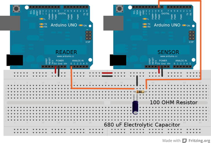
Figure 6-1 . RC low-pass filter setup
Listing 6-2 demonstrates the output by manipulating a variable that is declared as type byte and then written to the PWM pin 9. Any type of manipulation can be performed on the sensorOut variable by receiving commands from the serial monitor to set the output value, or computing a range to better match the sensor type being simulated (such as one that sweeps from 0 to 100°C).
Listing 6-2. Code to Be Uploaded to the Sensor Arduino
byte sensorOut = 0x00;

void setup() {
 pinMode(9,OUTPUT); // serial can be set up here
}// end void setup()

void loop() {
  sensorOut++; // the manipulation of the output variable
  analogWrite (9,sensorOut); // the actual sensor simulation
  delay(1000); // delay is to match the update speed of the sensor
}// end void loop()
Verifying the Code
Once everything is uploaded and set up, plug in the USB from the computer to the reader Arduino and start the serial monitor. The reader will print what it receives off the analog pin and print the voltage, the degrees Celsius, and the Fahrenheit conversion. The sensor Arduino will output from 0V to ∼5V at ∼0.02V per step, or approximately −50°C to 450°C at 2C° per step.
Resistor Ladder
The resistor ladder, or R-R2 ladder, offers the other method to give an Arduino analog out. It uses 20 resistors, with 9 being one value and the other 11 being twice that value. An R-R2 ladder is essentially a network of voltage dividers. This method works by chaining many digital inputs to one output by successively changing voltage across different sets of resistors. This is a parallel binary method of controlling the output voltage. The lowest significant bit is the input closest to the ground resistor, and the highest significant bit is on the opposite end of the chain connected to the output. Figure 6-2 demonstrates a schematic of the resistor ladder, in which Vin 0 is the lowest significant bit and will have the smallest voltage change when it is in a high state. You can expand a resistor ladder to any bit resolution by adding extra Vin n+1 units to the end of the ladder.

Figure 6-2 . R-R2 ladder schematic
The resistor values used can be arbitrary, as long as one value is twice the value of the other and not so great as to affect the final output. Decent values to start with are 1kΩ and 470Ω. With a stack of 5% resistors and a good voltmeter, it is possible to get a good 2:1 ratio with these resistors. You can make an R-R2 ladder scalable to any bit precision by adding or removing two resistors from the chain.
For this example, a 10-bit converter will be made to match the resolution of the Arduino’s ADC. Then the code will implement a 10-bit binary counter to control the constructed DAC. The resistor values will be referred to as 1R for the lower-value resistors and 2R for the ones of twice that value.
To get set up refer to Figure 6-3, start with one 2R and connect one end to ground and the other end to another terminal strip on the same side of the board. Then from that terminal strip in a continuing pattern down that side of the board place the nine 1R connecting, the last one to analog pin 0 on the reader Arduino. The remaining ten 2Rs have one end placed at all the junctions of the 1R and the other end connected to sensor Arduino pins starting from pin 2 to pin 11 in order from the resistor closest to the ground 2R. The other remaining connections are the 5V and ground pins between the Arduinos. The code for the reader is the same as loaded for the RC low-pass filter.
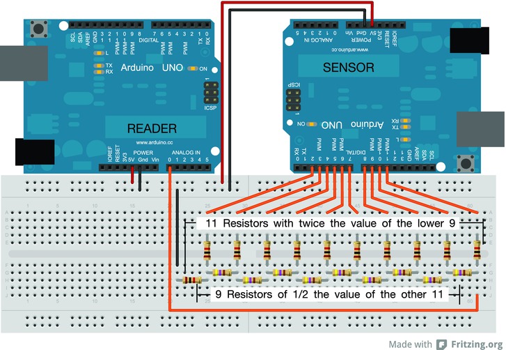
Figure 6-3 . R-R2 ladder setup
The sensor code implements a basic binary counter and introduces the use of programming an Arduino using the AVR registers. The use of the registers in some cases can simplify the code and make it smaller, but it also increases the complexity of the program. Four registers will need to be manipulated for this code: DDRB, DDRD, PORTB, and PORTD. The first four letters of these names refer to the register’s type, and the last letter designates which set of pins on the Arduino is being referenced. All the ports discussed are going to be 8 bits in size (or 2 nybbles).
- If the register descriptor is followed by a D, this refers to pins 0 through 7.
- If followed by a B, then it refers to pins 8 through 13, with the last two bits being unusable on anything being referenced to B.
Correlating the binary to the pin starts at the lowest significant bit as read, so to turn on pin 0 the Arduino PORTD will be equal to 0b00000001.
- The DDRx is the data direction register, which tells the pins whether to be input(0) or output(1). This is done by setting the DDRx equal to a byte of data, such as DDRD = 0b11100011, which will tell pins 7,6,5,1, and 0 to be outputs and pins 4, 3, and 2 to be inputs. Setting pins by this method is the same as calling the pinMode(pin, direction) function for each pin in the setup() function. If serial functions are still required, the two lower bits on xxxxD must be left alone, making the whole byte unavailable.
- Setting the PORTx register equal to a byte allows the groups of pins to be turned on or off within one line of code, depending on the bytes. In contrast, if a variable is set to equal a PORTx, then the contents of the register are read, and, depending on the mode that is set in the DDRx, will determine where the bits of data come from: internally for output(1) and externally for input(0).
You need to load the code from Listing 6-3 onto the Arduino to use it as the sensor. The code sets up pins 2 through 11 with the register to demonstrate the same function as pinMode(). The code then counts a variable of type unsigned int up to a value of 1024 so that the count will not continue to the maximum 16-bit value of 65535, truncating the count to 10 bits by an AND mask. The code then shifts the data to match the proper pins and masks out unneeded bits with the bitwise AND, placing the data in respective registers. Because the Arduino IDE is built on top of the AVR C compiler, nothing needs to be included or declared to use the register names; they can just be typed and work the same way as any variable.
![]() Caution Manipulating the registers directly is an advanced programming technique that may not work consistently on all Arduino-capable boards. Check the pin mapping for the specific board and the data sheet for the register. For example, the Arduino Mega PORTB controls pins 10 through 13 as the upper four bits and pins 50 through 53 for the lower four bits.
Caution Manipulating the registers directly is an advanced programming technique that may not work consistently on all Arduino-capable boards. Check the pin mapping for the specific board and the data sheet for the register. For example, the Arduino Mega PORTB controls pins 10 through 13 as the upper four bits and pins 50 through 53 for the lower four bits.
Listing 6-3. Sensor code
unsigned int manipVar=0; // the only variable needed to achieve output

void setup() {
DDRD = DDRD | 0b11111100; // set pins 2–7 as output  or leave pins 1,2
                          // alone for serial comunications
DDRB = DDRB | 0b00001111; // set 8–11 as output, leaving the rest alone
} // end void setup()

void loop() {
  manipVar++; // any manipulation can be performed on manipVar
  manipVar &= 0b0000001111111111; // mask that resets manipVar when 1024 is
                                  // reached
  PORTD = (manipVar << 2) & 0b11111100;// shift left by 2 bits then mask
                                       // to get pins 2–7 straight out of manipVar
                                       // then write value to pins on pins 2–7
  PORTB = (manipVar >> 6) & 0b00001111;// shift right by nibble+crumb
                                       // to set the value for pins 8–11
  delay (1000); // to match refresh of sensor type
} // end void loop()
Verifying the Code
With the code uploaded to both Arduinos and the breadboard populated, plug in the reader and start the serial monitor. The same information that was displayed in the last example will print to the screen this time, with approximately 0.0048V per step, or about 0.5°C and the same temperature range.
This method reduces the jitter that is associated with the RC filter and matches the maximum resolution of the ADC, making it a better choice to simulate an analog sensor. The disadvantages are the number of pins used, the number of parts, and the advanced programming method required to achieve a clean count. With the setup demonstrated in this section minus the delay, it takes around 4ms to count from 0 back to 0, making a ∼250HZ sawtooth wave and about 4μs between output changes. If the code is kept small, it is feasible to make a lightweight function generator out of an Arduino by looping a byte array; it is also feasible to simulate piezoelectric knock sensors.
![]() Note To explore this code a bit more, replace the R-2R ladder with an array of ten LEDs, hook up a potentiometer to analog 0, and then set manipVar equal to analogRead(0) and lower the delay to 100 ms. Power up and watch the conversion from the potentiometer to binary.
Note To explore this code a bit more, replace the R-2R ladder with an array of ten LEDs, hook up a potentiometer to analog 0, and then set manipVar equal to analogRead(0) and lower the delay to 100 ms. Power up and watch the conversion from the potentiometer to binary.
When working with sensors, it often feels like there are as many different ways to digitally work with them as there are sensor types. This section covers a common cross-section of communication styles. To simulate these sensors, it is important to match the specifications of the various protocols. Data can be sent or received, sent in any order, sent to multiple devices, or requested at any time, making some of these devices very difficult to implement. Both the devices and the Atmel data sheets are valuable resources for determining the best method needed to simulate a sensor.
PWM sensors are not as common as other types, but still deserve an honorable mention. PWM is commonly used to control servos; in a sense, PWM sensors replace the R/C receiver, which is arguably a type of sensor. Although the microcontrollers used in Arduino lack some elements to precisely match the specifications of a majority of the sensors that use PWM as a data mechanism, they are capable of reading them. The pulseIn() function can read the output PWM signal of another pin with enough consistency that a data correlation can be formed. The code that can be used to simulate a sensor of this type is similar to the code in Listing 6-2; couple that with a lack of sensors that implement PWM within the timing tolerances of the Arduino, and there is no need for an example in this section. The use of this style of passing digital information can be useful in the creation of other sensor packages.
Gray code is a digital method that uses two or more pins to produce a square wave that is out of phase from one sensor output pin to another. The method of phasing multiple signals allows the direction and position changes to be read at any time. The way in which the square waves are out of phase determines whether the bit shift is left or right. Gray code is also known as reflected binary, and is commonly used to make sensors that convert either linear or angular movement into countable pulses to determine position, direction, and speed. This is how scroll wheels on computer mice work. Gray code is also commonly used in robotics for rotary encoders. If one output is read as a reference signal on either a falling or rising logic, then the other outputs read at that time will denote the direction. If the second output is LOW before the first pin is read, it is moving one direction, and if HIGH, it is going the other direction.
The minimum amount of pins needed for this sensor is two for data and one for ground/voltage supply. The more logic pins a sensor has, the more accurate it can be, by providing the ability to error-check for missing pulses. Figure 6-4 shows the pulses of a dual-output encoder with one output read as rising and falling; the state of the second output depends on the shift direction of the first output at read time.
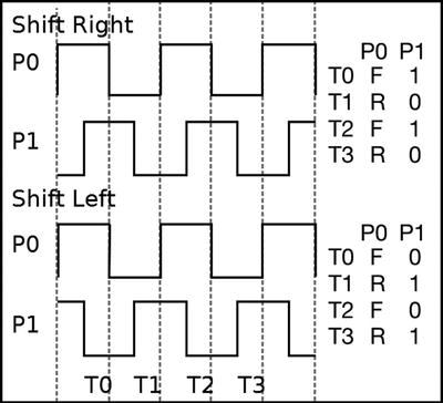
Figure 6-4 . Pulses of a dual-output encoder
It is up to the reader/controller to keep track of the pulses to determine if a full rotation or swing has been achieved. The code for the reader also has to determine the direction the gray code is shifting. For the sensor reader, Dr. Ayars wrote an article on how to read a rotary encoder (SparkFun part number COM-09117). In this example, the code increments/decrements a variable depending on the direction the encoder was traveling when the detent was reached, but not the number of rotations preformed. More information on reading this type of sensor is available on Dr. Ayars’ blog, at http://hacks.ayars.org/2009/12/using-quadrature-encoder-rotary-switch.html.
The technique used in Listing 6-4 is one method of reading gray code and is excellent for reading two output encoders. A more advanced method is needed for three or more pin encoders to achieve the error correction of positioning and count. The following code needs to be loaded on the Arduino to be used as the reader for the first half of this example.
Listing 6-4. Dr. Ayars’ Codewith Reworked Comments
byte Blinker = 13;
int Delay = 250;
byte A = 2;// 1st sensor Out pin
byte B = 3;// 2nd sensor Out pin
volatile int Rotor = 0; // sensor click count

void setup() {
   pinMode(Blinker, OUTPUT);
   pinMode(A, INPUT);
   pinMode(B, INPUT);
   digitalWrite(A, HIGH); // Turn on pull-up resistors
   digitalWrite(B, HIGH);
   attachInterrupt(0, UpdateRotation, FALLING);// use interrupt on pin A
   Serial.begin(9600);
}// end setup()

void loop() {
 digitalWrite(Blinker, HIGH); // Blink LED
  delay(Delay);               // any code can run here. the sensor will be
 digitalWrite(Blinker, LOW);  // updated upon interrupt on pin 2.
  delay(Delay);
} // end loop()
void UpdateRotation() {
  // update sensor's reading upon the falling edge of pin 2
 if (digitalRead(B)) {
  Rotor++;            // increment direction if second pin is HI
 }                    // at time of the interrupt
 else {
   Rotor--;           // decrement direction if second pin is LOW
 }                    // at time of the interrupt
 Serial.println(Rotor, DEC);
} // end UpdateRotation()
Outputting Gray Code
For the Arduino to mimic the gray code, it must produce multiple square waves that are evenly out of phase from one to another. Using a series of digitalWrite() function calls to control the output pins’ states and a delay() to control the phase is a perfect way to control a series of digital signals that need a specific order. One digitalWrite() is used per output of the rotary encoder to be mimicked, with a delay() after each write to make an overlap of the digital cycle. An encoder that has two outputs needs two digitalWrite() calls in a loop, with a delay() after each write, flipping the state that is written to the pin each time the loop is run. A square wave will be produced, having a total cycle time equal to twice the total delay time. Each time the loop is run, one half of the gray code cycle is output. The order in which the pins are manipulated determines the direction of the encoder; the orders are opposite if the forward order goes from pin 1 to 3 and the reverse order goes from 3 to 1. The percentage of time that the cycle is out of phase is controlled by the delay() after the digitalWrite(). To calculate the phase difference, the individual delay() is divided by total delay(). For two outputs having a total delay of 6ms and individual delays of 3ms, the second output is out of phase by 50 percent.
Some rotary encoders have outputs that are out of phase by 100 percent, being in completely opposite states. To achieve a four-output encoder with the third output being the opposite of the first output and still having an even distribution of phase, the first output has to flip state at the same time as the third, and the fourth output needs no delay, creating a cycle of 6ms with a 1ms phase shift. The cycle time created is representative of how fast the sensor can be manipulated.
To calculate the maximum rate an encoder can simulate, divide 60 by the total cycle time multiplied the total steps over a specific distance. The distance for rotary style is one revolution and the linear distance can be inches, centimeters, or another unit. The encoder being emulated for the example has a cycle of 12 steps per revolution. The shortest cycle time implemented by the reader code is 8ms, making the calculation 60s / (0.008s / step * 12 steps / revolution) = 625rpm. The digitalWrite() is negligible in calculating maximum manipulation speed. The added time is about 6.75μs for this code, giving a 0.3% tolerance. If the delay is removed, the sensor can run at about 1.8 million rpm.
Calculating the maximum speed capable is not for determining the delay to use, but for information about the application of the simulated hardware in control feedback loops. The delay to use between the pin writes should be at least 1ms, and a separate delay should be used to control and vary the manipulation speed. If the sensor code is having problems accurately reading the sensor’s output, increase the delay between the digitalWrite() function calls.
The setup for the hardware is as shown in Figure 6-5, with reader pins 2 and 3 connected to sensor pins 10 and 11, respectively. Two momentary switches used to control the direction of the output pulses are connected to ground and independently connected to sensor pin 2 for down and 3 for up. The code from Listing 6-5 needs to be loaded on the Arduino to be used as the sensor. The reader Arduino is loaded with the code from Listing 6-4. Simulating this rotary encoder requires one more pin than the actual sensor; the ground and 5V pins need to be connected between the two Arduinos.

Figure 6-5 . Gray code simulation setup
Listing 6-5. Arduino Sensor Code
byte first , second; // order of pin change
boolean click , stateChang;// send click and the state to change to variables

void setup() {
  pinMode(2 , INPUT); // encoder down button
  pinMode(3 , INPUT); // encoder up button
  pinMode(11 , OUTPUT); pinMode(10 , OUTPUT); // encoder outputs
  digitalWrite(2 , HIGH); digitalWrite(3 , HIGH);  // input pull-up resistors
  digitalWrite(10 , HIGH); // initial state
  digitalWrite(11 , LOW);
  stateChang = true;
}// end void setup()

void loop() {
  if (digitalRead(2) == 0 ){ // down
    first = 10; second = 11; // pin 10 writen befor pin 11 for down diretion
    click = true;
  }
  if (digitalRead(3) == 0 ){ // up
    first = 11; second = 10; // pin 11 written before pin 10 for up direction
    click  = true;
  }
  if (click == true ) {  // send 1/2 pulse when a button is pressed
  stateChang = !stateChang; // flip the state to be written
  digitalWrite(first, stateChang); // change 1st pin
  delay (2); // delay befor changinng next pin
  digitalWrite(second , stateChang); // change 2nd pin
  delay (2); // delay befor changning next pin at highest speed
  click = false ; // reset
  }
   delay (100); // slowing the code down = moving encoder slower
}// end void loop()
With everything set up, plug the reader Arduino into the computer and start the serial monitor. The reader prints the count when pin 2 transitions low, decrementing or incrementing the count depending on the incoming signal. The sensor Arduino will send one-half of the gray code per button press. If a button is held down, a continuous signal will be sent at a maximum rate of 208ms, as defined in the code. When the code is running and the buttons are not being pressed, the Arduino will be held in the last state. Using this sensor simulation is very helpful in debugging control code for robots CNC or any system using control loops.
![]() Note If an oscilloscope is not available to visualize what happens in the sensor code, increase all the delays to about 200ms and replace the reader with two LEDs.
Note If an oscilloscope is not available to visualize what happens in the sensor code, increase all the delays to about 200ms and replace the reader with two LEDs.
Serial communication is one of the cornerstone communication types in computer engineering, and many sensors communicate via this method. Serial sensors are capable of sending and receiving more information than analog sensors by sending data by the byte. Setting up a simulated serial sensor is simple on the Arduino using the built-inserial functions or with software serial. The trick is matching the baud rate and the actual data being sent; the specifications should be available on the sensor’s data sheet. It is recommended that software serial be used so that the other serial connection is still available for control and monitoring.
Outputting Serial Data
The sensor for this section is the blue Parallax RFID reader that transmits serial at a baud of 2400. The RFID reader reads special tags that contain a 40-bit identifier that is transmitted as ten hexadecimal numbers converted to plain ASCII. A byte with a value of 10 is sent at the beginning of the tag code and is ended by a byte value of 13; there is also a pin to activate the RFID reader. The code for the Arduino to access the RFID information is available at http://arduino.cc/playground/Learning/PRFID, in the section modified by Worapoht K. using software serial. Upload Listing 6-6 to the Arduino that will be used for retrieving the RFID data.
Listing 6-6. Worapoht K. Code with Reworked Comments
#include <SoftwareSerial.h>
int  val = 0; // temporary holder
char code[10]; // the Tag ID
int bytesread = 0; // byte count
#define rxPin 8 // RFID reader SOUT pin
#define txPin 9 // no connection

void setup() {
  Serial.begin(2400);  // Hardware serial for Monitor 2400bps

  pinMode(2,OUTPUT); // RFID ENABLE pin
  digitalWrite(2, LOW);    // Activates RFID reader
} // end void setup()
void loop() {
  SoftwareSerial RFID = SoftwareSerial(rxPin,txPin);
  RFID.begin(2400);
  if((val = RFID.read()) == 10) {   // check for header
    bytesread = 0;
    while(bytesread<10) {  // read 10-digit code
      val = RFID.read();
      if((val == 10)||(val == 13)) {  // check for a value of 10 or 13
        break;                       // stop reading
      }
      code[bytesread] = val;         // add the digit
      bytesread++;                   // ready to read next digit
    }
    if(bytesread == 10)  {  // if 10-digit read is complete
      Serial.print("TAG code is: ");   // possibly a good TAG
      Serial.println(code);            // print the TAG code
    }
    bytesread = 0;   // reset byte count
    delay(500);
  }
} // end void loop()
As shown in Figure 6-6, this simulated sensor setup is very similar to the actual sensor: pin 2 on both Arduinos are connected together, and pin 8 on the reader is connected to pin 9 on the sensor Arduino. Also, the 5V and GND need to be connected.
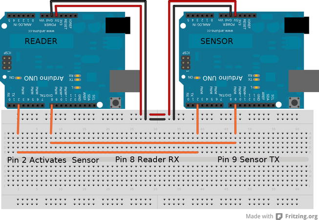
Figure 6-6 . RFID serial setup
Listing 6-7 shows the code for simulating the RFID.
Listing 6-7. RFID Simulator
#include <SoftwareSerial.h>

void setup() {
  Serial.begin(2400);  // Hardware serial for Monitor 2400bps
  pinMode(2,INPUT);
} // end void setup()

void loop() {
  SoftwareSerial RFID = SoftwareSerial(8,9); // pin 8 noconnect, pin 9 transmit
  RFID.begin(2400);
  if(LOW == digitalRead(2)) {   // does the sensor need to be active
  RFID.write(10);  // transmit header
  RFID.write("HelloWorld"); // transmit Tag ID code
  RFID.write(13); // transmit end
  }
} // end void loop()
Verifying the Code
Get everything uploaded and connected, and start the serial monitor running at 2400 baud. The code for simulating the RFID sensor sets up software serial at 2400 baud, and then waits for pin 2 to be low before sending the data sequence. The data that is sent to the reader Arduino starts with a byte value of 10 and ends with a byte value of 13. HelloWorld will then be printed to the serial monitor TAG code is:. HelloWorld just happened to be ten characters and can be replaced with actual tag codes. Sometimes incoherent data will be printed. This is caused by the serial not being synchronous. More code is needed to verify the data, but for this application, it just needs to get at least one good RFID code to compare to the list of valid codes to perform an action.
I2C
The communication method I2C, also known as two-wire, is a synchronous serial communication method using one wire for a clock signal and another wire for data. I2C is a cousin to basic serial, with a few differences in what the hardware does during communications. Sensors that use this type of communication can handle a wide variety of data, devices, and commands. Sensors that communicate via I2C can have multiple functions measuring multiple activities on the same package. The sensor that will be simulated in this section is the SRF10 Ultrasonic Ranger Finder. Its code is included in the Arduino IDE by selecting File ![]() Examples
Examples ![]() Wire
Wire ![]() SFRRange_reader, and should be loaded on the Arduino to be used as the reader.
SFRRange_reader, and should be loaded on the Arduino to be used as the reader.
I2C data transfers happen on one wire, meaning that one only device can transmit at a time; however, more than two devices can be connected together with just two wires. In most common I2C setups, there is one master device that is the receiver of the data and the controller of what devices communicate. Arduino includes a library that implements this communication, and for most basic setups, it works well, especially when used on the master device. The library lacks a bit of finesse that is required when attempting to simulate the workings of an I2C sensors, however.
Getting the best control to simulate sensors using I2C requires manipulating the hardware registers; this method of setting up the I2C bus is a bit more complicated, but isn’t difficult once you have a bit of understanding of the registers.
![]() Note Refer to section 22.5 in the ATmega 328P data sheet (pages 223–247); this section gives an overview of the I2C module included in the Arduino’s microcontroller.
Note Refer to section 22.5 in the ATmega 328P data sheet (pages 223–247); this section gives an overview of the I2C module included in the Arduino’s microcontroller.
I2C communications happen on analog pin 5 for the shared clock (SCL) and analog pin 4 for data (SDL). TWAR, TWCR, TWDR, and TWSR are the four registers that are used to set up I2C slave mode. TWBR is a fifth register in the I2C hardware and is unimportant for slave applications. TWBR is used in master mode to control the SCL speed. SREG is the one register outside the I2C module that will have to be modified for this section. Registers work the same way as variables in that all the manipulation methods for variables work the same way. The register names have already been defined by the main libraries used by the Arduino IDE; declarations to use them are not necessary. All the registers used in this section are 1 byte in size. Some of the registers are for data and others are for control.
The TWCR Register
The TWCR register is the two-wire control register; this is what defines the main working of the I2C communications. Each bit in the byte of the TWCR register controls a different function within the hardware; the name of the bit describes its location within the byte.
- To put the Arduino into slave mode, you must set the TWI Enable Acknowledge (TWEA) and TWI Enable (TWEN) bits to 1 in the TWCR. TWEN (bit 2) activates the I2C hardware, and TWEA (bit 6) tells the hardware to send acknowledgments when appropriate; if the TWEA is not set, this device will not respond to other devices trying to communicate.
- TWI Interrupt (TWINT) (bit 7) and TWI Interrupt Enable (TWIE) (bit 0) are the other two bits that are important in the TWCR and are used for software control. TWINT is a flag that gets set to 1 when there is something that needs attention from the software; the software then has to clear the flag by writing 1 to the TWINT bit when it’s finished handling what needed attention. You can also set up TWINT in conjunction with TWIE as an internal interrupt.
Data being transferred on the I2C is time sensitive, so it is wise to set the communications to be handled using the internal interrupts on the Arduino. This is accomplished by setting the TWIE and the global interrupt enable in the SREG to on. SREG needs to be set with a bitwise OR (|) mask so that the other bits are not manipulated, and has to be reset every time an interrupt happens. When the TWINT flag gets set to 1 by the hardware, the interrupt is triggered. The interrupt service routine (ISR(vector)) is run when an interrupt is triggered; the ISR() works very similarly to a normal function such as Setup() or Loop(). ISR() can be written directly in the Arduino sketch with no preceding information, but a vector is required. A vector is a name that describes the interrupt that the ISR responds to for code execution.
![]() Note A reference of the vector names used in the AVR libraries that the Arduino is built upon is located at www.nongnu.org/avr-libc/user-manual/group__avr__interrupts.html. The vector name that is needed for I2C interrupt on the Arduinos with the 328P chips is TWI_vect.
Note A reference of the vector names used in the AVR libraries that the Arduino is built upon is located at www.nongnu.org/avr-libc/user-manual/group__avr__interrupts.html. The vector name that is needed for I2C interrupt on the Arduinos with the 328P chips is TWI_vect.
The last register that has to be set to get the I2C slave to respond to information moving on the bus is an address. The address is set in the TWI Address Register (TWAR). The top seven bits (7-1) are the address; bit 0 tells the device that it is OK to respond to the general call address. The general call address is 0, and when the master sends this address, every device set to have a response will respond. When the address is set to the TWAR register, it has to shift to the left by 1, making 126 unique devices that can be on the I2C bus.
The TWI Data Register (TWDR) is where all the data bytes will go through. When this register is written (TWDR = FOO;), a data transfer will begin. To read the incoming data, read the data register into a variable (FOO = TWDR). I2C uses unique start and stop values to encapsulate the data; this leaves a full byte for data transmission. This is unlike plain serial, where a portion of a byte is used to denote the beginning and end of larger data amounts, as in the previous example. The TWI Status Register (TWSR) makes it easier to send larger variable types and keep them in proper order.
The TWSR register contains information about what is happening on the I2C bus, such as data direction, errors, and transmission requests. Reading the TWSR is important for controlling the software; there is a list of status codes in the TWI module section of the Atmel data sheet. 0X80 and 0XA8 are the codes of interest for simulating the sensor. 0X80 tells the code that there is incoming data that needs to be read, and 0XA8 tells the sensor to transmit its data. There are three bits in this register—located from 2 to 0—that are not important for the running of the slave and need to be masked out (0b11111000) by a bitwise AND (&); the status codes are calculated for this and do not need any shift.
Outputting I2C Data
Setting up the example as shown in Figure 6-7 involves using two pull-up resistors to make sure the SCL and SDA line are high in accordance with the requirements of I2C. The Arduinos are connected through analog pins 4 and 5, as well as ground and power. The code in Listing 6-8 is uploaded to the Arduino that is to be used as the sensor.
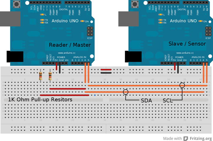
Figure 6-7 . I2C setup
The code demonstrates how to implement I2C communications by directly manipulating hardware registers while combining direct AVR C and Arduino code. For clarity, the value that is set to the registers is in binary, matching the position of the bit in the register. The code increments manipVar each time the loop function is run. The LED on the board turns on or off depending on the command received from the master. All the communication happens in the ISR() function; the data manipulated in the interrupt has to be global; it is not possible to pass data to the ISR() function, because it is called from hardware, not code.
Listing 6-8. I2C Simulated Sensor Code
byte address = 112; // address of this sensor
unsigned int manipVar = 0; // variable to change data
byte bytessent = 2 ; // number of bytes to send
byte bytestosend[2] ; // prepare data to send
byte command = 0 ; // command storage

void setup() {
TWAR = (address << 1) | 0b00000001; // set address and general call response
TWCR = 0b01000101; // set TWEA TWEN and TWIE to 1
SREG |= 0b10000000; // enable global interrupt
pinMode(13 , OUTPUT);
} //end void setup()

void loop() {
     if (command == 0x50){  // turn ON LED to a command 0x50
       digitalWrite (13 , HIGH);
     }
     if (command == 0x02){ // turn OFF LED to a command 0x02
       digitalWrite (13 , LOW);
     }
      manipVar++; // main variable to manipulate outdata two bytes
       bytestosend [0] = manipVar;  // prepare manipVar in to HI and LOW bytes
       bytestosend [1] = manipVar >> 8 ; // manipVar HI
      delay (250); // something else to do while wating
} // end void loop()

ISR (TWI_vect){  // interrupt service routine set to vector
    if (TWCR & (1 << TWINT)) {  // double-check for proper interrupt
       if ((TWSR & 0b11111000) == 0x80){ // incoming data
        command = TWDR; // copy command data for future use
        TWCR = 0b11000100; // reset back to original config
       }
       if ((TWSR & 0b11111000) == 0xA8 ) { // request for outgoing data
         while (bytessent > 0 ){ // send bytes to master
           bytessent--;
           TWDR = bytestosend [bytessent]; // send data from HI to LOW byte
           TWCR = 0b11000101; // reset for each send
           delay (5); // pause a moment on send
         }
           if (bytessent == 0 ){ // reset byte count check to see if empty
           bytessent = 2;
           }
       } // end if ((TWSR & 0b11111000) == 0xA8 )
       TWCR = 0b11000101; // one last reset to make sure
       SREG |= 0b10000000; // reenable interrupt
    } // end if (TWCR & (1 << TWINT))
} // end ISR (TWI_vect)
With everything set up and loaded onto the respective Arduinos, plug the reader into the USB and start the serial monitor. Consecutive numbers should print to the screen, counting up, and the simulated sensor’s LED should blink when the master sends specific commands. Using direct register manipulation to replicate sensors allows maximum control of the I2C interface that the library does not currently allow.
![]() Note Chapter 10 on multi processing, covers methods of SPI communication that can be applied for sensor simulation.
Note Chapter 10 on multi processing, covers methods of SPI communication that can be applied for sensor simulation.
Summary
The techniques described in this chapter are not limited to sensors, and can be applied to other systems that move data from one component to another. This chapter focused on the connection of the sensor to the Arduino, because that is the most difficult hurdle in simulating sensors.
When writing code to simulate sensors, work slowly and tackle one part of the sensor at a time to avoid complications. Also take the time to practice writing code to simulate sensors that are readily available for verification against the code you created.