![]()
Writing Your Own Arduino Libraries
Arduino libraries are written in standard C/C++ code and contain either a set of useful functions or an object that is initialized and used in Arduino sketches. The advantage of this is that you can share these libraries across your own projects and with other users. In this chapter, we will create an example “Hello World” library, a Motor control library, and a more complex DS1631 I2C temperature sensor library.
What you need to know to write your own libraries
The choice to program libraries in C or C++ is up to you. Standard C works when using the Arduino library conventions. If you plan to use structs and enum variables you will have to place them in a header file.
C++ gives you the ability to create objects, but since we are working with an 8-bit MCU, there is limited memory space and usually little or no memory management. Make sure to test your code for memory use and heap fragmentation. Remember that not everything must be an object; it is acceptable to have a set of functions that you use as libraries without writing them from scratch for each sketch.
The major difference between Arduino sketches and Arduino libraries is that a sketch is pre-processed, meaning that you do not have to prototype your functions or write a header file for your main sketch. For this reason, a sketch is easy to use and a good starting place for beginners. Libraries, on the other hand, have to conform to the full rules of C/C++. The C/C++ compiler is powerful, but if you use functions, and variables before they are defined, the compiler will indicate an error and ultimately fail. A helpful metaphor is the idea of enrolling a course that has a required prerequisite, but the system cannot identify what the prerequisite is.
A compiler reads from the top of the file to the bottom. If any variables or functions depend on others and one is not defined, an error occurs. These prototypes and header files are a list of all the functions and variables used in the sketch and library code. The only solution is to place a prototype of your function at the top of your sketch or in the header file. For example, let’s say you a have a function that adds two integers. The prototype would be:
int add(int aa, int bb);
The prototype needs only minimal information about return type, function name, and expected types that it will encounter. The implementation, on the other hand, can be done any way that follows the rules set by the prototype.
int add(int aa, int bb) {
 int res = aa + bb;
 return res;
}
Another valid implementation:
int add(int aa, int bb) {
 return aa + bb;
}
Preprocessing scans the sketch for functions and libraries that are included in your sketch. This process generates a file that ends in the .h extension—the standard extension for a header file. Arduino does that for you, but libraries require a header file and an implementation file. The header file is a list of all the function signatures, including the return type, function name, and the function parameters. In certain cases, you will need to use in-line functions in order to an optimizing goal. If you are defining your library as a C++ object, you should including the following information in the header file: what the object inherits from, the object class name, when functions are members of the class, and whether these functions are public or private.
![]() Note Arduino IDE forces the implementation file to have the *.cpp extension. If you use *.c, you will get errors.
Note Arduino IDE forces the implementation file to have the *.cpp extension. If you use *.c, you will get errors.
One reason you may opt for a C function rather than a C++ object has to do with the potentiometer. In order to read a potentiometer, you issue a function like analogRead(A0). If all you are doing is reading values from the potentiometer, you are already in good shape. Creating a single potentiometer as an object takes memory and can quite easily overcomplicate a simple read from a device. However, if you are trying to avoid a huge number of global variables, it makes sense to have a single object contain all of the information. If needed, you can create libraries just for a single sketch. If your code starts to take multiple pages and you are writing many helper functions, you can transfer that code into sketch-based libraries. Your project will load with all the library code together, and you’ll see multiple tabs. Eventually, you may want to use those libraries in more than one project. To do so, you will need to separate each into their own library area and package them to install easily across the system. Header files can also be used to create hardware profiles. The pins indicate what is used for custom shields, breadboard circuits, and even custom Arduino-compatible boards. This would allow for portable code between hardware devices and configurations.
Figure 12-1 shows the #include "HardwareProfile.h", which pulls in the header file HardwareProfiles.h. In this file, you can define custom variables for a piece of hardware and set their default values.
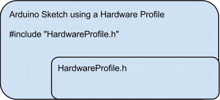
Figure 12-1. Hardware Profile included into an Arduino Sketch
Listing 12-1. Example defines in HardwareProfile.h
#define motor1Dir 7
#define motor2Dir 8
#define motor1PWM 9
#define motor2PWM 10
#define motor1Enable 11
#define motor2Enable 12
Listing 12-1 shows a set of pins defined from the Motor Library example. This guarantees that you use the correct pins every time you work with the same hardware. If you need to change from the default pins, you can redefine the pin numbers in your sketch.
Creating a simple library
There are typically two “Hello World” programs for Arduino. One blinks an LED on and off, and the other sends a "Hello, World!" message over the serial connection. Here, we will convert the sketch into a simple library. Figure 12-2 shows a visualization of the library, implementation, and sketch file that we are creating.
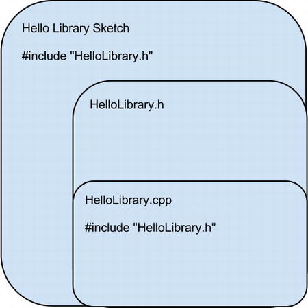
Figure 12-2. SimpleHello.ino sketch and code layout
The starter sketch for this is example is Listing 12-2.
Listing 12-2. Initial sketch code
const int LED_PIN = 13;
void setup()
{
  Serial.begin(9600);
  pinMode(LED_PIN, OUTPUT);
}
void loop()
{
  Serial.println("Hello, World!");
  digitalWrite(LED_PIN, HIGH);
  delay(1000);
  digitalWrite(LED_PIN, LOW);
  delay(1000);
}
There are several small details in this code that we can clean up and place into a library. The pin can differ between boards, so we will want to define a default pin of 13 and allow for it to be overridden.
![]() Note Not all boards have the same LED pin. For example the Arduino Ethernet board uses pin 9.
Note Not all boards have the same LED pin. For example the Arduino Ethernet board uses pin 9.
To create libraries, first create a main sketch, and then add the libraries to that sketch. Since the sketch is an auto-generated header file, the library you create cannot have the same name as the sketch. Let’s start by creating the library’s header file, HelloLibrary.h. In order to create a new library, you have to use a special part of the Arduino IDE. In Figure 12-3, there is a drop down arrow just below the serial monitor button.
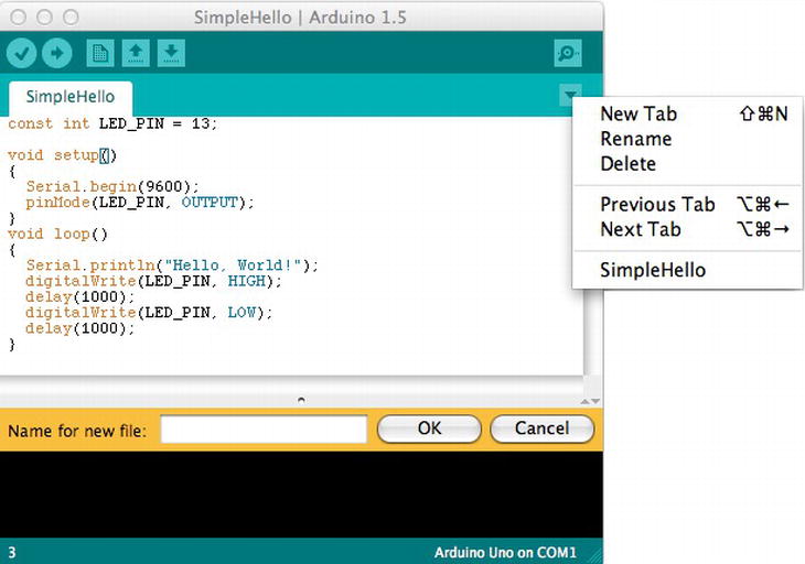
Figure 12-3. SimpleHello.ino sketch with “New Tab” option
Make sure your sketch contains the code from Listing 12-2. Then, in Figure 12-3, select “New Tab” from the triangle menu. You will be prompted to create a file. Call this new file "HelloLibrary.h". Once you have created the new file, enter Listing 12-3.
Listing 12-3. HelloLibrary Header File
/*
*
 * HelloLibrary Header file
 *
 */
#ifndef HelloLibrary_h
#define HelloLibrary_h

#if defined(ARDUINO) && ARDUINO >= 100
#include "Arduino.h"
#else
#include "WProgram.h"
#endif

#define LED_PIN 13
void printHelloLibrary();
void startBlink(int duration);
#endif
If you were programming strictly in C, you may want to name the HelloLibrary implementation file as HelloLibrary.c, but the Arduino compiler process will be looking for HelloLibrary.cpp. Normally, it is okay to put C code in the *.cpp file. Next, we will create the HelloLibrary.cpp implementation file. The HelloLibrary.cpp code that we will use for the implementation is shown in Listing 12-4. It is important to note that the implementation file needs to include a reference to the header file. This way, the created functions will conform to the header specification at compile time.
Listing 12-4. HelloLibrary cpp implementation file
/*
*
 * HelloLibrary cpp implementation file
 *
 */

#include "HelloLibrary.h"
void startBlink(int duration)
{
  digitalWrite(LED_PIN, HIGH);
  delay(duration);
  digitalWrite(LED_PIN, LOW);
  delay(duration);
}

void printHelloLibrary()
{
  Serial.println("Hello Library");
}
The code that causes the actions is now in place in Listing 12-4, and it is almost identical to the code that we made in the main sketch. Once the library is created, the main HelloLibrarySketch.ino sketch resembles Listing 12-5. It includes HelloLibrary.h, as well as the functions and definitions defined in the library that are now available to any application that communicates with the library.
Listing 12-5. Revised main sketch code
/*
*
 * Hello Library Example
 *
 */

#include "HelloLibrary.h"
void setup()
{
}

void loop()
{
  printHelloLibrary();
  startBlink(1000);
}
Listing 12-5 outlines the pattern that all libraries follow. Include the library at the top of the file, and the compiler will process the library, and then you can access the functions according to C/C++ principles. In libraries, there is a common pattern for adding enumerations (enum) and structures (struct) to your code. You can use these as types in your code, but only if you write a function that has them as a return type or parameter. Because of the preprocessing, you cannot put them in your main sketch, but you will need to add them to a header file. For example, you may want to keep track of the part of the day—morning, afternoon, evening, or night. It is possible to do this in one of two ways.
- Using #define:
#define MORNING 0
#define AFTERNOON 1
#define EVENING 2
#define NIGHT 3 - Using an enumeration:
enum {MORNING, AFTERNOON, EVENING, NIGHT};
There is an automatic assigning of values starting from 0 and growing by one, until the final one is reached. This can be overridden, and each can be initialized to a specific value.
enum {
MORNING = 1,
AFTERNOON = 3,
EVENING = 5,
NIGHT = 7
};
For this reason enum sequences are not typically iterated. You should use a different data type for values that you want to iterate.
The other common C feature is structures. Structures are referred to as structs and similarly must be implemented in a header file in order to be used as parameters or return types for functions.
struct position {
        int xx;
        int yy;
};
This struct would declare a position to have an X and Y value. In strict C, you would have to declare the struct or enum with typedef, but in C++ this is not required. This struct could be added to our Hello Library header file, as indicated in Listing 12-6.
Listing 12-6. Position struct in header file HelloLibrary.h updated
/*
*
 * HelloLibrary Header file
 *
 */
#ifndef HelloLibrary_h
#define HelloLibrary_h

#if defined(ARDUINO) && ARDUINO >= 100
#include "Arduino.h"
#else
#include "WProgram.h"
#endif

#define LED_PIN 13
struct position {
        int xx;
        int yy;
};

void printHelloLibrary();
void startBlink(int duration);
#endif
Then the Position struct could be used in the main sketch, as shown in Listing 12-7.
Listing 12-7. Code using the Position struct
#include "HelloLibrary.h"
void setup()
{
Serial.begin(9600);
position Position;
Position.xx = 20;
Position.yy = 30;
Serial.print("Position X: ");
Serial.print(Position.xx);
Serial.print(" Y: ");
Serial.println(Position.yy);
}

void loop()
{
}
Listing 12-7 uses the struct from the header file in the setup portion of the main sketch. Without using libraries to hold these values, you must prototype them manually in the main sketch, which makes the code less portable to other projects. Using libraries unlocks the real power of C/C++, where function definitions, function parameters and return types can conform to the rules that were defined in your library.
Making a Motor Library
Robots help us get the most out of our movement code. We may have many robots based on the same motor driver chips, so most motor movement can be done from a generic motor library that targets a set of common pin compatible motor control chips. For a more in-depth look, we will create a motor library initially based on the L293D chip. In some cases, like Texas Instruments SN754410, they are pin compatible and need to be modified. However, if a different pin layout were used for a new shield, then the pins would have to be redefined . This project is a based on the IEEE Rutgers motor controller shield, https://github.com/erosen/Line-Following-Robot, with two 5-volt motors. The goal is to convert it to a library that conforms to the Arduino and can be easily distributed for anyone using either chip. In this example, we will create a motor object using the basic C++ features of a class with both private and public methods.
A motor controller needs three types of defined pins: motor direction, the pulse width modulation (PWM), and motor enable. These pins enable the motor behavior—for example: on or off and spin forward or backward. The motor will spin at a particular rate controlled by voltage approximated by the PWM pins. Since these pins can change from board to board, we need a way to set a default set of pins and then an override so that custom pins can be used. For instance, software PWM could be used instead of the physical PWM pins that are indicated by the Arduino type.
The example code we are using in Figure 12-8 already supports many helpful features. You can also write directly to the pins to make the motors move. To enable a motor, set the direction and move it to write:
digitalWrite(motor1Enable, HIGH);
digitalWrite(motor1Dir, HIGH);
analogWrite(motor1PWM, 128);
Given these basic features, we can control the motor for forward, back, left, right, stop, and various speeds. In a standard Arduino sketch you would end up cutting and pasting them repeatedly, which is not very sustainable. The next step is to create some useful functions that help to avoid cutting and pasting, so we do not end up with code that is difficult to read. The final step is to create a library that organizes these functions so that you can use them in multiple robot or motor projects. The starting sketch is shown in Listing 12-8.
Listing 12-8. Initial motor controller code
#define motor1Dir 7
#define motor2Dir 8
#define motor1PWM 9
#define motor2PWM 10
#define motor1Enable 11
#define motor2Enable 12

void initMotorDriver()
{
  pinMode(motor1Dir, OUTPUT);
  pinMode(motor2Dir, OUTPUT);

  pinMode(motor1Enable, OUTPUT);
  pinMode(motor2Enable, OUTPUT);
  digitalWrite(motor1Enable,HIGH);
  digitalWrite(motor2Enable,HIGH);
  setLeftMotorSpeed(0); // make sure the motors are stopped
  setRightMotorSpeed(0);
}

void setMotorVel(int dirPin, int pwmPin, int velocity)
{
  if (velocity >= 255)
  {
    velocity = 255;
  }
  if (velocity <= −255)
  {
    velocity = −255;
  }

  if (velocity == 0)
  {
    digitalWrite(dirPin, HIGH);
    digitalWrite(pwmPin, HIGH);
  }
  else if(velocity <0)
  { // Reverse
    digitalWrite(dirPin, HIGH);
    analogWrite(pwmPin, 255+velocity);
  }
  else if(velocity >0)
  { // Forward
    digitalWrite(dirPin,LOW);
    analogWrite(pwmPin, velocity);
  }

}

void setLeftMotorSpeed(int velocity)
{
  //Serial.print("Set Left: ");
  //Serial.println(velocity);
  setMotorVel(motor1Dir, motor1PWM, -velocity);

}

void setRightMotorSpeed(int velocity)
{
  //Serial.print("Set Right: ");
  //Serial.println(velocity);
  setMotorVel(motor2Dir, motor2PWM, -velocity);
}

void setup()
{
  initMotorDriver();
  setRightMotorSpeed(255);
  setLeftMotorSpeed(−255);
  delay(500);
  setRightMotorSpeed(−255);
  setLeftMotorSpeed(255);
  delay(500);
  setRightMotorSpeed(0);
  setLeftMotorSpeed(0);

}

void loop()
{
  //Go Forward 5 secs
  setRightMotorSpeed(355);
  setLeftMotorSpeed(255);
  delay(5000);
  //Stop
  setRightMotorSpeed(0);
  setLeftMotorSpeed(0);

  //loop here forever.
  while(1);

}
In the initial sketch, the individual control commands are combined into one function called setMotorVel:
void setMotorVel(int dirPin, int pwmPin, int velocity)
The direction is set by integer velocity, which accepts −255 through 255. If the velocity is negative, then the opposite direction is enabled.
Listing 12-8 code defines the pins that are mapped to control the chip. This defines a motion function that controls all the options, and there are helper functions that make it easy to initiate left and right control of the robot. Now, we are ready to make the library. These functions will move into their own header file, .h and their own implementation file, .cpp. At this step, we want to create the appropriate project structure.
Listing 12-9. Motor controller header file Motor.h
#ifndef Motor_h
#define Motor_h

#if defined(ARDUINO) && ARDUINO >= 100
#include "Arduino.h"
#else
#include "WProgram.h"
#endif

#define motor1Dir 7
#define motor2Dir 8
#define motor1PWM 9
#define motor2PWM 10
#define motor1Enable 11
#define motor2Enable 12

class Motor
{
 public:
    Motor();
    void begin();
    void setLeftMotorSpeed(int velocity);
    void setRightMotorSpeed(int velocity);

 private:
    void setMotorVel(int dirPin, int pwmPin, int velocity);
};
#endif
Here is what the implementation file looks like:
#include "Motor.h"
Motor::Motor()
{
  pinMode(motor1Dir, OUTPUT);
  pinMode(motor2Dir, OUTPUT);

  pinMode(motor1Enable, OUTPUT);
  pinMode(motor2Enable, OUTPUT);
  digitalWrite(motor1Enable,HIGH);
  digitalWrite(motor2Enable,HIGH);
  setLeftMotorSpeed(0); // make sure the motors are stopped
  setRightMotorSpeed(0);
}

void Motor::setMotorVel(int dirPin, int pwmPin, int velocity)
{
  if (velocity >= 255)
  {
    velocity = 255;
  }
  if (velocity <= −255)
  {
    velocity = −255;
  }

  if (velocity == 0)
  {
    digitalWrite(dirPin, HIGH);
    digitalWrite(pwmPin, HIGH);
  }
  else if(velocity <0){ // Reverse
    digitalWrite(dirPin, HIGH);
    analogWrite(pwmPin, 255+velocity);
  }
  else if(velocity >0){ // Forward
    digitalWrite(dirPin,LOW);
    analogWrite(pwmPin, velocity);
  }

}

void Motor::setLeftMotorSpeed(int velocity)
{
  //Serial.print("Set Left: ");
  //Serial.println(velocity);
  setMotorVel(motor1Dir, motor1PWM, -velocity);

}

void Motor::setRightMotorSpeed(int velocity)
{
  //Serial.print("Set Right: ");
  //Serial.println(velocity);
  setMotorVel(motor2Dir, motor2PWM, -velocity);
}
Once the implementation code is in place, it is time to work on the main sketch that will use the code. To avoid cutting and pasting the code into every sketch, we can just write #include "Motor.h". The following sketch example shows the code controlling the motor and using features of the library, which is much shorter and cleaner than the original sketch in Listing 12-8.
Listing 12-10. Motor controller main sketch
.#include "Motor.h"
Motor motor;

void setup()
{

  motor.setRightMotorSpeed(255);
  motor.setLeftMotorSpeed(−255);
  delay(500);
  motor.setRightMotorSpeed(−255);
  motor.setLeftMotorSpeed(255);
  delay(500);
  motor.setRightMotorSpeed(0);
  motor.setLeftMotorSpeed(0);

}

void loop()
{
  //Go Forward 5 secs
  motor.setRightMotorSpeed(255);
  motor.setLeftMotorSpeed(255);
  delay(5000);
  //Stop
  motor.setRightMotorSpeed(0);
  motor.setLeftMotorSpeed(0);

  //loop here forever.
  while(1);
}
The amount of code for the sketch file is greatly reduced. Now, the sketch is about controlling the robot and less about implementing the low-level motor controlling code. The code can be adapted to be used system-wide across multiple projects.
The anatomy of an Arduino library folder
The previous code shows how to create a library that is available to an individual Arduino sketch, rather than a system-wide sketch that all programs can use. As you continue to develop a set of libraries, you will want to structure them so that other people can use them. This means creating a readme.txt and a keywords.txt, moving examples to their own directory, and placing utility code into a utilities folder, all of which is shown in Figure 12-4.

Figure 12-4. Motor library directory structure
- Library Name: The folder that contains the motor library will be listed with the library name; for instance MotorLibrary not Motor.h
- Examples: These can be demo programs or test sketches that people will find useful when using your library.
- Utilities: A folder for utility code is not needed for main functionality, but provides help code.
- Doc: A documentation folder where .pdf, .txt, or .html files go with documentation for the library.
- Header files: Our example uses Motor.h, but you may have many other header files in your project. Those would all go in this directory.
- Implementation file: This example uses Motor.cpp, but other libraries can have one or more implementation files.
- License: The license your libraries will be distributed under, such as the GNU Public License (GPL).
- keywords.txt: This contains the formatting to highlight the functions and variables that a user will see in the Arduino IDE.
All of these directories and files need to be compressed into a .zip compressed archive file for download and installation by extracting them into the Arduino libraries folder. Let’s examine critical features in more detail.
Examples Folder
The example folder contains all of your example sketches that demonstrate features and instructions. By having examples, your library will appear in the “examples” menu. When your library does not have examples, it will only be found in the “import library” menu. There are occasions where you write several libraries and they all share the same library. In this case, it makes sense to omit additional examples.
![]() Note New users may be confused and not be able to locate the library if it does not have at least one example.
Note New users may be confused and not be able to locate the library if it does not have at least one example.
License
The license file can be anything from GPL to “all rights reserved.” If you are building on top of open source software, the license should be compatible. For Open Hardware check out the Open Source Hardware Association (OSHWA) at http://www.oshwa.org/; they maintain the definition of Open Hardware and have helpful information on what licenses are available.
keywords.txt
This file consists of the datatypes, methods, functions, and constants sections. A data type in parenthesis denotes the section. However, a tab character must separate these key and value pairs. Any spaces will cause the parsing to fail, with no indication as to what is wrong.
# Datatypes (KEYWORD1)
Motor KEYWORD1
# Methods and Functions (KEYWORD2)
setMotorVel    KEYWORD2
setLeftMotorSpeed    KEYWORD2
setRightMotorSpeed    KEYWORD2
# Constants (LITERAL1)
motor1Dir LITERAL1
![]() Note Even before your code is completed in this format, it is good practice to make it a version-controlled project and enable issue tracking. This is explained in detail in Chapter 2.
Note Even before your code is completed in this format, it is good practice to make it a version-controlled project and enable issue tracking. This is explained in detail in Chapter 2.
Installing Arduino Libraries
The libraries are normally installed in the user sketch folder under libraries. Complete libraries are stored there for use in any Arduino sketch. Installation typically consists of extracting the library into the Arduino libraries folder.
If you have placed your code in a version control system like GitHub, users can click the download option and extract or clone the project into the default libraries folder. This is a very efficient way to distribute the code and make it communally available.
Using Arduino Libraries
Once a library is extracted and placed, it is ready for use. The code that references the libraries will need to be updated in one of the following formats.
- To look for a system-level library:
#include <Motor.h>
- To look in the project directory for the library:
#include "Motor.h"
The #include with caret bracketing (< >) indicates a system library, and it will search the library area for your code. This step can be easily overlooked, so be careful and check that you have the correct symbols.
Arduino Objects and Library Conventions
C libraries do not use constructors and destructors. The library simply provides a set of previously created functions and variables. However, in order to use a library, there may be some set-up configuration necessary. This initialization would be in a begin() function, where all necessary elements of the library are configured. However, C++ supports objects that typically have a constructor, which is invoked when the object is created. Conversely, a destructor is invoked when the object is removed from memory, which means begin() is not always needed.
A destructor would usually be defined as a way to clean up the object on delete. However, delete in the AVR environment is not always available. You can free up pins and clean up after the object is finished, or you can use an end() function activated in the void setup() portion of an Arduino sketch.
![]() Note Destructors are not typically used. The examples have the destructors removed.
Note Destructors are not typically used. The examples have the destructors removed.
The setup() function should include all the starting maintenance and object initialization in addition to the constructor. One key reason to use the begin() function is that variables, objects, or communications may not be initialized yet. For instance, if you want to use the Wire (I2C) library in a library or object, the Wire.begin() function must be enabled before your object can use the Wire library. At some point, the user may want to end the use of an object so that the end() function can be accessed, which takes care of any necessary cleanup. The recommended Arduino best practice for writing libraries that have some kind of sequential data includes using “read” and “write” functions instead of “send” and “receive”.
One common temperature sensor is the DS1631 I2C. It is essential to review the characteristics of the device in order for the code to use these features. This includes going to the data sheet http://datasheets.maxim-ic.com/en/ds/DS1631-DS1731.pdf, on which you can derive the following information.
This is an I2C slave device, which has a pin configurable address for up to eight devices on the same I2C chain as the master device.
This is represented by the 7-bit control byte defined here:
- Bit 0: r/w
- Bit 1: A0
- Bit 2: A1
- Bit 3: A2
- Bit 4: 1
- Bit 5: 0
- Bit 6: 0
- Bit 7: 1
We frequently work with these numbers in hexadecimal format. You will see device configuration that looks like this:
0x90
The way to read it is:
- 9 is 1001
- 0 is 0000
That would mean the device address is 0 and writable. The address corresponds to three bits, A0, A1, A2, and the last bit in the sequence configures if the device is in both write and read mode. So, read-only would look like 0001. The address only needs the 000, so in the implementation, we shift the address by one bit. Then the piece of code looks like this:
_addr = 0x90 >> 1;
Now the address can be used to reference the device. The goal with our code is to put those details into the constructor so that the data sheet can be directly read and the address can be pulled from it without forcing the programmer to make the shift. This also means that the user must wire the DS1631 with a valid address. Then, they must define the address for the library or object. When we configure the object, we require an address. The Arduino I2C master sets the control byte in order to tell the correct DS1631 what command to receive.
Ideally, the programmer will be able to use or hide the commands as needed during the implementation stage. So, startConversion() can be done without the programmer knowing the internal commands, such as the fact that 0x51 means “start conversion”. This applies to any of the appropriate and defined commands. For use in the Wire library, these must be converted into a hexadecimal form.
The commands are as follows:
- Start Convert: 0x51
- Stop Convert: 0x22
- Read Temperature: 0xAA
- Access TH: 0xA1
- Access TL: 0xA2
- Access Config: 0xAC
Software POR: 0x54 Registers:
- Temperature, 2 bytes, read only
- Configuration, 1 byte, read/write or set read-only
- Trip point: High, 2 bytes, read/write
- Trip point: Low, 2 bytes, read/write
We will want to obtain and/or set this information. The trigger trip points are very useful because we can set actions to occur if we leave a common boundary. Additionally, we can have interrupts that respond to both high and low conditions.
We will not be using the trip point registers in this example, but they can be found with the website in the final library code.
A typical set of functions would be the getters and setters for those registers:
getConfig();
setConfig();
getTemp();
The goal for the main Arduino sketch is to print out the temperature at specified intervals. When we distribute the code, this will be moved into the examples folder. We also need to create DS1631.h, and DS1631.cpp in the same sketch folder. Then, we will move the code to its own Arduino generic library. Here’s the initial library code, starting with the header file:
Listing 12-11. DS1631 I2C temperature sensor Arduino library DS1631.h
/*
 * DS1631 library object.
 * Registers R1, and R2 are used to set 9, 10, 11, 12 bit temperature resolution
 * Between a range of -55C to +125C
 * A0, A1, A2 are used to set the device address. Which is shifted by the library for use.
 * 1-SHOT readings or Continuous Readings can be configured
 * 12 bit resolution can take up to 750ms to be available
 * Temperature is returned in a 16 bit  two's complement Th, and Tl Register
 * The signed bit S, S = 0 for positive, and S = 1 for negative
 */

#ifndef DS1631_h
#define DS1631_h

#if defined(ARDUINO) && ARDUINO >= 100
#include "Arduino.h"
#include "pins_arduino.h"
#else
#include "WProgram.h"
#include "pins_arduino.h"
#endif

#define DEV0 0x90
#define DEV1 0x91
#define DEV2 0x92
#define DEV3 0x93
#define DEV4 0x94
#define DEV5 0x95
#define DEV6 0x96
#define DEV7 0x97

class DS1631
{
public:
  DS1631(uint8_t _ADDR);
  void begin( );
  byte getConfig();
  void setConfig(uint8_t _ADDR);
  float getTemp();
  void stopConversion();
  void startConversion();

private:
  float calcTemp(int msb, int lsb);
  uint8_t _addr;
  uint8_t _temp[2];
};
#endif
Listing 12-11 defines all the valid device addresses that can be used with the object. It is configured so that when reading the data sheet, the hexadecimal I2C address can be used as listed. Since the header file only shows the signature for the functions, we can tell what the class name, constructor, and destructor are for the defined object.
![]() Note With the AVR GCC, there is not effective memory management. Objects will not get deleted, so the constructor is not used and can be eliminated from the code.
Note With the AVR GCC, there is not effective memory management. Objects will not get deleted, so the constructor is not used and can be eliminated from the code.
As there is no effective memory management, the destructor is not used and no memory will be deallocated. The private variables are declared here, and the compiler will enforce them. If you try to directly access _addr, _temp[2], or calcTemp(), the compiler will show an error indicating that you are trying to access private values. By reviewing this code, you can get a quick idea of the functions and the types of parameters that are defined. This information will be used to ensure that the implementation corresponds to the values that are represented in the header file.
It is possible to describe more than one object in a single header file, but this can confuse library users, so it is best to create only one object per header file. If a set of objects will never be used separately from one another, it may make sense to define more than one object in the same header file.
Listing 12-12. DS1631 I2C temperature sensor implementation DS1631.cpp
#include <Wire.h>
#include "DS1631.h"

uint8_t _temp[2];
uint8_t _addr;

DS1631::DS1631(uint8_t _ADDR)
{
  //Cannot use Wire.begin() here because at declaration time it is unavailable.
  //Shift the address so the user can use the address as described in the Datasheet
  _addr = _ADDR >> 1;
}

void DS1631::begin()
{
}

void DS1631::stopConversion()
{
  Wire.beginTransmission(_addr);
  Wire.write(0x22); //stop conversion command
  Wire.endTransmission();
}

void DS1631::startConversion()
{
  Wire.beginTransmission(_addr);
  Wire.write(0x51); //start conversion command
  Wire.endTransmission();
}

byte DS1631::getConfig()
{
  byte config;
  stopConversion();
  Wire.beginTransmission(_addr);
  Wire.write(0xAC); //get configuration command
  Wire.endTransmission();
  Wire.requestFrom(_addr, (uint8_t) 0x01); //The configuration is one byte get it
  while (Wire.available())
  {
    config = Wire.read();
  }

  Wire.endTransmission();
  startConversion();
  return config;
}

void DS1631::setConfig(uint8_t config)//configuration options
{
  stopConversion();
  Wire.beginTransmission(_addr);
  Wire.write(0xAC); //get configuration command
  Wire.write(config); //configure with options
  Wire.endTransmission();
  startConversion();
}

float DS1631::getTemp() //0xAA command Read Temp, read 2 bytes, one shot temperature read
{
  unsigned char _temp[2];
  int count = 0;

  Wire.beginTransmission(_addr);
  Wire.write(0xAA); // start reading temperature now
  Wire.endTransmission();

  delay(750); //750ms reqiured to get 12 bit resolution temperature
  Wire.requestFrom(_addr,  (uint8_t)2); //get the 2 byte two's complement value back
  while(Wire.available())
  {
    _temp[count] = Wire.read();
    count++;
  }
  float temp = calcTemp(_temp[0],_temp[1]);
  return temp;
}

float DS1631::calcTemp(int msb,  int lsb)
{
  float num = 0.0;
  //Acceptable, but only 2-3 significant digits
   // num = ((((short)msb<<8) | (short)lsb)>>6) / 4.0;
  lsb = lsb >> 4; // shift out the last 4 bits because they are 0
  if (msb & 0x80) // Compare the sign bit = 1, then less than 0;
  {
    msb = msb - 256;
  }
  // Float conversion
  num = (float) (msb + lsb*0.0625);
  return  num;
}
The work of implementing the header file is done in the implementation file. Each of the I2C commands needs to be configured exactly to the data sheet. The constructor takes the defined address and shifts it the required one bit in order to be a proper address on the I2C bus. The details of the I2C communication protocol are wrapped inside the functions so that a library user only needs to have some knowledge of the data sheet.
We have a setConfig(uint8_t) and a uint8_t getConfig() that will accept and display the configuration of the temperature sensor.
The datasheet explains that the temperature is in Celsius and is stored in two’s complement formats, which mean that the most significant bit is the whole number, and the least significant bit is the decimal place. The float getTemp() function returns the Celsius temperature by calling calcTemp(); this is a private function that the sketch cannot call. There are many ways to do calcTemp(); it could be turned into a virtual function and be overridden by the programmer, but by separating it from getTemp(), it is possible to add flexibility to the library.
Listing 12-13. DS1631 I2C main sketch DS1631Example.ino
/*
 * DS1631_CPP Library Example
 */

#include <Wire.h>
#include "DS1631.h"

uint8_t conf = 0x0C;
uint8_t dev1 = DEV0;

DS1631 TempSensor(dev1); //Wire.begin hasn't happened yet
void setup()
{
  Serial.begin(9600);
  Wire.begin();

  TempSensor.stopConversion();
  TempSensor.setConfig(conf);
  byte config = TempSensor.getConfig();
  Serial.print("Config: dev:");
  Serial.print(DEV0, BIN);
  Serial.print(" set: ");
  Serial.print(config, BIN);
  Serial.print(conf, BIN);
  Serial.print(" get: ");
  Serial.println(config, BIN);
}

void loop()
{
  float temp = TempSensor.getTemp();
  Serial.print("TempC: ");
  Serial.print(temp, 4);
  Serial.print(" tempF: ");
  Serial.println((temp*9/5) + 32, 4);
}
One key point is that Wire.begin() must be initiated for any I2C communication to occur. This explains why Wire.begin() is established early in the setup() code, before TempSensor.setConfig(conf) is called. The Serial library can print float values so the temperature returned as float would be printed automatically with two decimal points, but because we have more detail, the code specifies four decimal places.
Lastly, it is possible to have up to eight DS1631 temperature sensors on one Arduino. In this version of the library, the sketch would contain an array of sensors each configured with their own address, as follows:
DS1631 TmpSense[8] = {
  DS1631(DEV0),
  DS1631(DEV1),
  DS1631(DEV2),
  DS1631(DEV3),
  DS1631(DEV4),
  DS1631(DEV5),
  DS1631(DEV6),
  DS1631(DEV7)
};
This code initializes all of the possible DS1631 I2C devices and can be used to monitor all eight possible sensors. You can access sensor four by calling TmpSense[4].getTemp(). You can use a for loop to read through the array and obtain all the sensor values. Lastly, in order to get the most from the library, you must document how the device names are defined; otherwise, users of the library will have to examine the header file and deduce all of the features. Another benefit of using libraries is to organize convenience functions like Fahrenheit conversion as shown in the loop code in Listing 12-13. A good follow up exercise is updating the library to support getTempC() and getTempF().
One benefit of using Listing 12-12 is that we abstract away the details of configuring the temperature sensor, making the main sketch code simpler; we only need to configure and use the device. The library and the object contain all the code that are typically cut and pasted into the main sketch. This allows the user to avoid major headaches by using the temperature sensor instead of debugging the code.
Summary
Arduino libraries are powerful tools for sharing code between projects and users. This code is organized for bundling and easy distribution. In this chapter we showed how to create libraries in a specific sketch directory. You can now choose whether to write C style libraries or C++ object based libraries. Then, we explained how to convert that directory into an Arduino wide library. The Motor controller evolved from a single sketch to a powerful library with many helpful commands that control a robot or a set of motors. The other major example shows how to interact with devices using the I2C protocol and makes those devices easier to access and use. We also reviewed the steps necessary to take a library from a single project and make it available to all of your code system-wide. The next steps are to check your library code into GIT and share the project with other Arduino users as we described in Chapter 2.