
Chapter 9. Identity
RFID (radio frequency identification) has long been hailed as the next big thing in identification. In reality, it’s slowly been becoming part of everyday life. RFID has largely replaced bar codes in warehouses, but bar codes are still used with individual consumer packages of products. RFID can be read from a distance, and it can store more data than a bar code. For example, a bar code identifies a product as “1 liter of Foobar, Inc. milk.” An RFID tag can also tell you that this specific carton was carton number 12,209,312, uniquely identifying it.
Biometric identification is getting commonplace. Many laptops have a fingerprint reader to protect you from bystanders “shoulder-surfing” as you type your password. Most governments want to store fingerprints and digitally readable facial images of every citizen with the excuse of using them in passports. The digital passports also have a standard for storing an iris image, even though that’s not used yet. DNA markers are already used for identifying criminals.
The benefit of biometric identification is that it’s always with you. The biggest downside is that once it’s copied by the adversary, it’s not possible to change it. For example, you can’t change your fingerprints. In practice, many cheap biometric sensors can be easily misled. There have also been claims that even professional, manual fingerprint identification is not as reliable as has been assumed.
Keypad is likely the most common method for identification. Just think how many times a week you type your PIN into different devices.
Keypad
A keypad is a quick way to type in some numbers. If you used a cell phone when they still had keypads, you might remember that keypads work well with one-handed use, and some people could even type numbers (or text!) without looking at the phone. You have similar keypads in television remote controls and microwave oven controls. Keypad are also used for password entry. You have probably used one with an ATM, numeric door lock, or a burglar alarm.
This experiment uses inexpensive numeric keypad, http://dx.com part number 149608, “DIY 4 x 4 16-Key Numeric Keypad - Black,” shown in Figure 9-1. The wiring used is similar to many other cheap number pads.

For Raspberry Pi, you could just use a normal USB keyboard or a USB number pad.
Under each key, vertical and horizontal wires cross. When you press a key, it connects the wires at each crossing.
To find out which key is pressed, you need to take one of the vertical columns LOW, but leave all the other columns HIGH. If one of the horizontal lines goes LOW, the key that was pressed is the one where the HIGH lines cross. If there is no match, test the rest of the columns until you find a key that was pressed. The code keeps testing columns, returning to the first column to check for more keypresses.
Keypad Code and Connection for Arduino
Figure 9-2 shows the connections for the keypad and Arduino. Wire it up as shown, and run the sketch shown in Example 9-1.

Arduino has internal pull-up resistors. When a digital pin is in INPUT mode, digitalWrite(pin, HIGH) connects it to +5 V through 20 kOhm resistor.
// keypad.ino - read 16-key numeric keypad (dx.com sku 149608)// (c) BotBook.com - Karvinen, Karvinen, Valtokariconstintcount=4;//charkeymap[count][count]={//{'1','2','3','A'},{'4','5','6','B'},{'7','8','9','C'},{'*','0','#','D'}};constcharnoKey='n';bytecolumns[count]={9,8,7,6};//byterows[count]={5,4,3,2};unsignedintlastReadTime;unsignedintbounceTime=30;// msvoidsetup(){Serial.begin(115200);lastReadTime=millis();for(inti=0;i<count;i++){pinMode(rows[i],INPUT);digitalWrite(rows[i],HIGH);// pull up //pinMode(columns[i],INPUT);}}voidloop(){charkey=getKeyPress();if(key!=noKey){Serial.(key);}delay(100);}// This does not support multiple presses. first one is// returnedchargetKeyPress(){charfoundKey=noKey;if((millis()-lastReadTime)>bounceTime){////Pulse columns and read row pinsfor(intc=0;c<count;c++){//Start pulsepinMode(columns[c],OUTPUT);//digitalWrite(columns[c],LOW);//Read rowsfor(intr=0;r<count;r++){if(digitalRead(rows[r])==LOW){////Find right characterfoundKey=keymap[r][c];//}}digitalWrite(columns[c],HIGH);pinMode(columns[c],INPUT);//if(foundKey!=noKey){break;}}lastReadTime=millis();}returnfoundKey;}

The count of keys vertically and horizontally. It’s a 4 by 4 keypad.

Map the position of the key (e.g., column 0, row 1) to the key number (“4”). The keymap is a two-dimensional array.

Map columns (e.g., column 2) to Arduino digital pins (D7).

Pull up each row pin (D6, D7, D8, D9), so that when they are not connected, they go HIGH. Using the internal pull-up saves you a bunch of external pull-up resistors!

Check that the difference between uptime, as measured by millis(), and the time of the last read is more than 30 ms. This is the typical program pattern for checking that enough time has passed. In this program, the main program loop() never calls this function more often than once in 100 ms, due to the
delay()inloop(). The check is useful when you start using getKeyPress() in your own programs outside this example.
Turn the current (vertical) column LOW. Other columns are left HIGH.

If a row is LOW…

… then the pressed key is in the intersection of the column you set LOW and the row that went LOW.

In our tests, a column in OUTPUT mode seemed to interfere with the readings. Setting it to INPUT mode sets it to high impedance (off), thus allowing correct readings.
Keypad Code and Connection for Raspberry Pi
Figure 9-3 shows the wiring diagram for Raspberry Pi. Hook everything up as shown, and run the program in Example 9-2.
Try USB keyboards and USB number pads with Raspberry Pi. Just like any keyboard, a USB number pad works automatically when plugged in. You can use raw_input() or pyGame to read keypresses, just like on your normal laptop or desktop.

# keypad.py - read 16-key numeric keypad (dx.com sku 149608)# (c) BotBook.com - Karvinen, Karvinen, Valtokariimporttimeimportbotbook_gpioasgpio#keymap=[]keymap.append(['1','2','3','A'])#keymap.append(['4','5','6','B'])keymap.append(['7','8','9','C'])keymap.append(['*','0','#','D'])columns=[2,3,14,15]#rows=[18,17,27,22]lastReadTime=NonebounceTime=0.03# sdefinitializeKeyPad():forxinrange(len(rows)):gpio.mode(rows[x],'in')gpio.mode(columns[x],'in')defgetKeyPress():globallastReadTimefoundKey=Noneif((time.time()-lastReadTime)>bounceTime):##pulse columns and read pinsforcinrange(len(columns)):gpio.mode(columns[c],'out')gpio.write(columns[c],gpio.LOW)#forrinrange(len(rows)):ifgpio.read(rows[r])==gpio.LOW:#foundKey=keymap[r][c]#gpio.write(columns[c],gpio.HIGH)gpio.mode(columns[c],'in')#ifnotfoundKey==None:break#lastReadTime=time.time()returnfoundKeydefmain():globallastReadTimeinitializeKeyPad()lastReadTime=time.time()whileTrue:key=getKeyPress()ifnotkey==None:(key)time.sleep(0.1)# sif__name__=="__main__":main()
-
Make sure there’s a copy of the botbook_gpio.py library in the same directory as this program. You can download this library along with all the example code from http://botbook.com. See GPIO Without Root for information on configuring your Raspberry Pi for GPIO access.
-
Map the key’s physical position (e.g., row 1, column 0) to a key label (“4”).
-
Map a column number (e.g., 2) to a gpio pin (gpio 14).
-
Check that the keypad is not read more often than once every 30 ms. The check is useful when you start using getKeyPress() in your own programs. In this example, the main() function calls getKeyPress() so rarely that the check is redundant. The
time.time()function returns the time as seconds since the Unix epoch, such as 1376839738.068395. This is compared with the time of the last keypress read, also stored as seconds since the epoch. The epoch is 00:00:00 UTC on January 1, 1970.-
Take one column (vertical) LOW. Others are left HIGH.
-
If a row became LOW, other rows are pulled HIGH by the physical pull-up resistor, as you can see in Figure 9-3.
-
The key that was pressed is at the intersection of LOW column and LOW row.
-
Put the column back to
"in"mode, so that it’s high impedance (off) and doesn’t affect the measurements.-
Break out of the
forloop (because a pressed key was found).
Environment Experiment: Revealing Fingerprints
How can you bypass a keypad, short of breaking it?
You could try all the combinations, but that’s a lot of trial and error. For example, there are a lot of three-character permutations in a 16-key pad.
16 * 16 * 16 = 16**3 = 4096
Can you see which keys are pressed most? In a keypad that’s been used a lot, the paint or sticker on frequently used keys could be worn.
You probably have a new keypad. Press the same code a couple of times. Try, if you can, to see grease on well-used keys by using bright light (Figure 9-4).

What if you pulverize graphite from a pencil or take some beauty powder and spread that on keys? What if you clean the keys before typing the combination? Does it matter if your fingers are greasy?
Latent (hidden) fingerprints can be captured with cyanoacrylate superglue vapor. Even though this is a very efficient technique for glass and plastic, cyanoacrylate fumes are unhealthy and must be handled in a fume hood. Also, superglue annoyingly sticks to everything.
Did you find the three most used keys? Now there are fewer to try, as you just have to find the correct order of these three keys.
3 * 3 * 3 = 3**3 = 27
Fingerprint Scanner GT-511C3
A fingerprint scanner is a more sophisticated identification device than the keypad. It is unique and won’t get lost or forgotten. Also you don’t have to worry about someone shoulder surfing as you type in a password.
The GT-511C3 fingerprint scanner (Figure 9-5) uses serial pins to communicate with Arduino or Raspberry Pi. Its protocol is described in the data sheet, available by searching the Web for “GT-511C3 data sheet” and from the distributor’s (SparkFun) catalog page.
The scanner can store the fingerprints into its own memory, making it easier to use from Arduino.
The GT-511C3 fingerprint scanner communicates at 9600 bit/s over serial port. The scanner is sometimes slow to respond, so you should configure the serial port for an extra-long timeout with setTimeout(), as shown in the next example program.
The protocol consists of packages. This code stores fingerprint images in the scanner, so only command packages are used (see Table 9-1). The header and device are always the same, and checksum is always calculated the same way. The part that changes is your command and parameter.
| Purpose | Example contents | Comment |
Header | 0x55 0xAA | Same for all command packages |
Device ID | 1 | Always the same, fixed on device |
Parameter | 0 | Turn off |
Command | 0x12 | Control LED (CMD_LED) |
Checksum | Sum of bytes |

The microcontroller (master) sends a command package to the scanner (slave). Commands include the following:
- Light up an LED.
- Delete all fingerprints from scanner memory.
- Enroll 1 (scan and store a new fingerprint to slot one).
- Identify (scan a fingerprint and tell if it’s one of the stored fingerprints).
The scanner responds with a command package. The response command is either ACK (acknowledge, OK, success) or NACK (negative acknowledge, failure, error). The parameter in the answer contains additional information, such as the following:
- ID of recognized fingerprint
- The fact that fingerprint is unknown
- Error code
The most common error codes are 100F (connection already opened) and 100A (memory is empty).
You can get a lot done with the code in this chapter. But if you need more details about the fingerprint sensor, search the Web for “GT-511C3 datasheet.”
Fingerprint scanners are vulnerable to fake fingers. Gelatin, like that found in gummy bears, is an easy material to get started with. Other materials include Scotch tape, Play-Doh, and printed transparency with Blu-Tack. The choice of material for fake prints depends on the technique used in the target fingerprint scanner. Chaos Computer Club has published information on extracting fingerprints from objects and using them for creating fake fingerprints.
Fingerprint Sensor Code and Connection for Arduino Mega
Use the Arduino Mega for easier debugging. Mega has multiple serial ports, so you can connect the fingerprint scanner to one serial and use another for USB code upload and debugging.
If you want a cheaper option, try the Arduino Leonardo. Although it looks a lot like an Arduino Uno, the Leonardo has the advantage of having two serial ports. Unlike the Uno, the RX/TX pins (pins 0 and 1) and the USB/Serial port are not tied together. With the Leonardo, Serial refers to the USB/Serial port, and Serial1 refers to pins 0 (RX) and 1 (TX). If you use the Leonardo instead of the Mega, you will need to change the example code and the circuit wiring to use Serial1 (pins 0 and 1) for the fingerprint scanner instead of Serial3 (pins 15 and 14).
Figure 9-6 shows the connection diagram for Arduino. Wire it up as shown, and then run the sketch shown in Example 9-3.
Difficult code! This code is more difficult than some other code examples in this book: it uses pointers to convert between a struct and a byte buffer. You don’t have to completely understand it to use it. You could just build the circuit, upload the code, and enjoy your fingerprint reader. But if you want to understand it, read on.
Arduino uses 5 V, but fingerprint sensor uses 3.3 V. Excessive voltage could destroy the sensor, reduce its usable age, or cause incorrect readings. In this project, you’ll use a voltage divider to reduce the voltage given by the Arduino TX pin. All you need are two resistors.
You don’t need a voltage divider on the sensor’s TX pin, because it has a maximum of 3.3 V—much less than Arduino’s RX pin. Arduino will still recognize 3.3 V as HIGH, because it’s more than half of 5 V.

// fingerprint_scanner.ino - learn and recognize fingerprints with GT-511C3// (c) BotBook.com - Karvinen, Karvinen, Valtokari// Requires Arduino Mega for extra serial portconstbyteSTX1=0x55;//constbyteSTX2=0xAA;constwordCMD_OPEN=0x01;//constwordCMD_CLOSE=0x02;constwordCMD_LED=0x12;constwordCMD_GET_ENROLL_COUNT=0x20;constwordCMD_ENROLL_START=0x22;constwordCMD_ENROLL_1=0x23;constwordCMD_ENROLL_2=0x24;constwordCMD_ENROLL_3=0x25;constwordCMD_IS_FINGER_PRESSED=0x26;constwordCMD_DELETE_ALL=0x41;constwordCMD_IDENTIFY=0x51;constwordCMD_CAPTURE_FINGER=0x60;constwordACK=0x30;//constwordNACK=0x31;//Errorstructpackage{//byteheader1;byteheader2;worddeviceID;unsignedlongparam;wordcmd;wordchecksum;};constintSIZE_OF_PACKAGE=12;/* To calculate checksum we add all bytes in pdu together. */wordcalcChecksum(structpackage*pkg){//wordchecksum=0;byte*buffer=(byte*)pkg;//for(inti=0;i<(sizeof(structpackage)-sizeof(word));i++){checksum+=buffer[i];}returnchecksum;}intsendCmd(wordcmd,intparam){//structpackagepkg;pkg.header1=STX1;pkg.header2=STX2;pkg.deviceID=1;//pkg.param=param;pkg.cmd=cmd;pkg.checksum=calcChecksum(&pkg);//Serial.println("Sending command");byte*buffer=(byte*)&pkg;//intbytesSent=Serial3.write(buffer,sizeof(structpackage));if(bytesSent!=sizeof(structpackage)){Serial.println("Error communicating");return-1;}intbytesReceived=0;charrecvBuffer[SIZE_OF_PACKAGE];//structpackage*recvPkg=(structpackage*)recvBuffer;//bytesReceived=Serial3.readBytes(recvBuffer,sizeof(structpackage));//if(bytesReceived!=SIZE_OF_PACKAGE){Serial.println("Error communicating");return-1;}if(recvPkg->header1!=STX1||recvPkg->header2!=STX2){//Serial.println("Header error!");return-1;}if(recvPkg->checksum!=calcChecksum(recvPkg)){Serial.println("Checksum mismatch error!");return-1;}if(recvPkg->cmd==NACK){Serial.println("NACK - Cmd error!");Serial.("Error:");Serial.println(recvPkg->param,HEX);return-1;}returnrecvPkg->param;}//All custom codes here as they may use variables defined in protocol implementation.voidsetup(){Serial.begin(115200);//Serial3.begin(9600);//Serial3.setTimeout(10*1000);// ms //}voidflashLed(inttime){sendCmd(CMD_LED,1);delay(time);sendCmd(CMD_LED,0);}voidloop(){Serial.println("Sending open command");sendCmd(CMD_OPEN,0);//Delete all fingerprints on start for testing purpose only.if(sendCmd(CMD_DELETE_ALL,0)>=0){//Flash LED 3 times for victory dance and to indicate that we are ready for enrolling.flashLed(500);delay(500);flashLed(500);delay(500);flashLed(500);}Serial.println("Starting capture");intid=0;id=sendCmd(CMD_GET_ENROLL_COUNT,0);//sendCmd(CMD_LED,1);sendCmd(CMD_ENROLL_START,id);Serial.println("Press finger to start enroll");intret=0;WaitForFinger(false);Serial.println("Capturing finger");ret=sendCmd(CMD_CAPTURE_FINGER,1);//if(ret<0){EnrollFail();return;}Serial.println("Remove finger");sendCmd(CMD_ENROLL_1,0);WaitForFinger(true);Serial.println("Press finger again");WaitForFinger(false);ret=sendCmd(CMD_CAPTURE_FINGER,1);if(ret<0){EnrollFail();return;}Serial.println("Remove finger");sendCmd(CMD_ENROLL_2,0);WaitForFinger(true);Serial.println("Press finger again");WaitForFinger(false);ret=sendCmd(CMD_CAPTURE_FINGER,1);if(ret<0){EnrollFail();return;}Serial.println("Remove finger");ret=sendCmd(CMD_ENROLL_3,0);if(ret!=0){EnrollFail();return;}WaitForFinger(true);flashLed(500);delay(500);flashLed(500);delay(500);Serial.println("Enroll completed");Serial.println("Press finger for identify");sendCmd(CMD_LED,1);// IdentifyWaitForFinger(false);ret=sendCmd(CMD_CAPTURE_FINGER,1);//if(ret<0){IdentFail();return;}ret=sendCmd(CMD_IDENTIFY,0);//if(ret>=0&&ret<200){Serial.("ID found:");Serial.println(ret);flashLed(500);delay(500);flashLed(500);delay(500);flashLed(500);delay(500);flashLed(500);delay(500);flashLed(500);delay(500);flashLed(500);delay(500);}else{Serial.println("ID not found");}sendCmd(CMD_CLOSE,0);delay(100000);}voidWaitForFinger(boolbePressed){delay(500);if(!bePressed){while(sendCmd(CMD_IS_FINGER_PRESSED,0)>0){delay(200);}}else{while(sendCmd(CMD_IS_FINGER_PRESSED,0)==0){delay(200);}}}// Flash LED 3 times for failure// and close device.voidIdentFail(){Serial.println("Ident failed!");flashLed(500);delay(500);flashLed(500);delay(500);flashLed(500);delay(500);sendCmd(CMD_CLOSE,0);}// Flash LED 4 times for failure// and close device.voidEnrollFail(){Serial.println("Enroll failed!");flashLed(500);delay(500);flashLed(500);delay(500);flashLed(500);delay(500);flashLed(500);sendCmd(CMD_CLOSE,0);}
-
Command package header. As this code doesn’t read the fingerprint images, data packets are not used.
-
Commands as described in the data sheet. 0x is the hexadecimal prefix (see Hexadecimal, Binary, and Other Numbering Systems).
-
Possible return values: ACK (acknowledge) meaning success, NACK (negative acknowledge) meaning failure.
-
Command package structure. The exact length of variables will come into play later, when you use the struct to decode received data. See Table 9-1.
-
The checksum is the sum of all bytes.
-
To process every byte, the
*pkgmust be converted to abytebuffer.-
sendCmd()sends one command and returns the parameter from the response. It returns -1 for any errors.-
The device ID is fixed on the device side. It must still be accounted for, so that the raw bytes converted from this struct will be correct.
-
Convert the command package struct to raw bytes for transmitting.

The receive buffer is the exact same length as the command package struct.

The
*recvPkgpointer sees the receive buffer as a struct. You can later use this pointer to easily access the variables, as inrecvPkg->cmd.
Fill the receive buffer with bytes, not worrying about what they mean yet.

Using the struct package pointer, the individual values of struct are easily accessible. This would not have been possible with a plain byte buffer.

This first serial port is serial over USB. You can access it from within the Arduino IDE with Tools→Serial Monitor. Debugging is much easier when you can send output to the serial monitor.

The fingerprint scanner is connected to Serial3. This connection is available on Arduino Mega but not on Arduino Uno.

The scanner is sometimes slow, so we extend the timeout to 10 seconds.

Find the first free slot.

Parameter 1-slow capture, 0-quick image.

Scan the finger to be identified.

Identify the last scanned finger. The return value of
sendCmd()will be the id of the finger (1, 2 or 3) or 0 for an unidentified finger.
Fingerprint Sensor Code and Connection for Raspberry Pi
To use the serial port in Raspberry Pi, you must first release it from use as a login terminal. See Enabling the Serial Port in Raspberry Pi. Wire up the scanner as shown in Figure 9-7, and then run the code in Example 9-4.
To access the serial port from Python, you need to install the PySerial library by running the command:
sudo apt-get update && sudo apt-get install python-serial
The connection for Raspberry Pi is simple—even simpler than the connection for Arduino. Raspberry Pi uses 3.3 V for HIGH, the same as the fingerprint sensor. As the voltage is already correct, you don’t need resistors to build a voltage divider with Raspberry Pi.

# fingerprint_scanner.py - learn and recognize fingerprints with GT-511C3# (c) BotBook.com - Karvinen, Karvinen, ValtokariimporttimeimportserialimportstructSTX1=0x55#STX2=0xAACMD_OPEN=0x01#CMD_CLOSE=0x02CMD_LED=0x12CMD_GET_ENROLL_COUNT=0x20CMD_ENROLL_START=0x22CMD_ENROLL_1=0x23CMD_ENROLL_2=0x24CMD_ENROLL_3=0x25CMD_IS_FINGER_PRESSED=0x26CMD_DELETE_ALL=0x41CMD_IDENTIFY=0x51CMD_CAPTURE_FINGER=0x60ACK=0x30#NACK=0x31port=NonedefcalcChecksum(package):#checksum=0forbyteinpackage:checksum+=ord(byte)returnint(checksum)defsendCmd(cmd,param=0):#package=chr(STX1)+chr(STX2)+struct.pack('<hih',1,param,cmd)#checksum=calcChecksum(package)package+=struct.pack('<h',checksum)#sent=port.write(package)if(sent!=len(package)):"Error communicating"return-1recv=port.read(sent)#recvPkg=struct.unpack('cchihh',recv)#ifrecvPkg[4]==NACK:("error:%s"%recvPkg[3])return-2time.sleep(1)returnrecvPkg[3]defstartScanner():("Open scanner communications")sendCmd(CMD_OPEN)defstopScanner():("Close scanner communications")sendCmd(CMD_CLOSE)defled(status=True):ifstatus:sendCmd(CMD_LED,1)else:sendCmd(CMD_LED,0)defenrollFail():("Enroll failed")led(False)stopScanner()defidentFail():("Ident failed")led(False)stopScanner()defstartEnroll(ident):sendCmd(CMD_ENROLL_START,ident)defwaitForFinger(state):if(state):while(sendCmd(CMD_IS_FINGER_PRESSED)==0):time.sleep(0.1)else:while(sendCmd(CMD_IS_FINGER_PRESSED)>0):time.sleep(0.1)defcaptureFinger():returnsendCmd(CMD_CAPTURE_FINGER)defenroll(state):ifstate==1:returnsendCmd(CMD_ENROLL_1)ifstate==2:returnsendCmd(CMD_ENROLL_2)ifstate==3:returnsendCmd(CMD_ENROLL_3)defidentifyUser():returnsendCmd(CMD_IDENTIFY)defgetEnrollCount():returnsendCmd(CMD_GET_ENROLL_COUNT)defremoveAll():returnsendCmd(CMD_DELETE_ALL)defmain():("Remove all identities from scanner")startScanner()removeAll()led()("Start enroll")newID=getEnrollCount()(newID)startEnroll(newID)("Press finger to start enroll")waitForFinger(False)ifcaptureFinger()<0:enrollFail()returnenroll(1)("Remove finger")waitForFinger(True)("Press finger again")waitForFinger(False)ifcaptureFinger()<0:enrollFail()returnenroll(2)("Remove finger")waitForFinger(True)("Press finger again")waitForFinger(False)ifcaptureFinger()<0:enrollFail()returnifenroll(3)!=0:enrollFail()return("Remove finger")waitForFinger(True)("Press finger again to identify")waitForFinger(False)ifcaptureFinger()<0:#identFail()returnident=identifyUser()if(ident>=0andident<200):#("Identity found:%d"%ident)else:("User not found")led(False)stopScanner()if__name__=="__main__":try:ifport==None:port=serial.Serial("/dev/ttyAMA0",baudrate=9600,timeout=None)#main()exceptException,e:eport.close()finally:port.close()
-
Command package header (see Table 9-1).
-
The commands from the data sheet. 0x indicates a hexadecimal number (see Hexadecimal, Binary, and Other Numbering Systems for more information).
-
An ACK (acknowledge) reply means success.
-
Each command package has a checksum. The checksum is the sum of bytes.
-
The
sendCmd()function sends a command package and reads the response. It returns the parameter in the response, or a negative number for any errors.-
Pack the Python variables into raw bytes for transmission. The header bytes STX1 and STX2 are concatenated. The
paramandcmdvalues are packed withstruct.pack: little endian (<), short signed two-byte integer (h), and normal four-byte integer (i).-
The calculated checksum is appended to the raw bytes. The
pack()function converts checksum to little endian (<) and short signed two-byte integer (h).-
Read the response. The command packages are always the same length, so you can use the length
sentas the number of bytes to read.-
Unpack the raw data to a tuple. The parameters to
struct.pack()are: normal one-byte char (c), short int (h), and normal int (i).-
Given the command
CMD_CAPTURE_FINGER(0x60), the scanner returns a negative return value for an error. No identification is attempted yet. ThecaptureFinger()function simply sends this command and returns its value.-
The
identifyUser()function returns the id for recognized finger (1, 2, 3) or a negative number for unknown finger.-
The scanner communicates at 9600 bits/second. In Linux, serial ports are raw device files. The scanner can be slow to answer, so the timeout needs to be disabled (which is what we did here) or set to a long value. The timeout is specified in seconds (you can use floating point for fractions of seconds).
RFID with ELB149C5M Electronic Brick
Radio frequency identification (RFID) offers cheap, unique object identification from a distance. It’s already used a lot in warehouses, and as prices go down, it’s making its way to consumer packages. Some pets have microchips in the neck so that they can be identified even if they lose their collar tags. In Finland, some libraries use RFID instead of EAN bar codes.

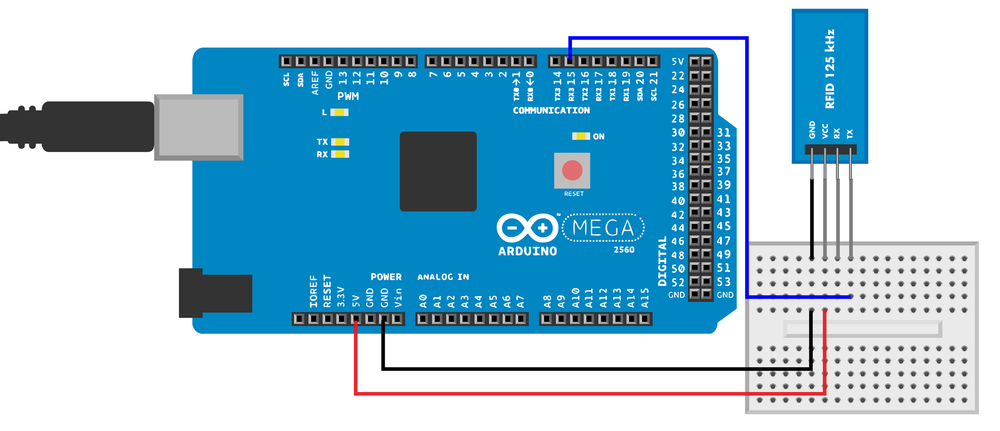
There are multiple RFID standards that differ on price, reading distance, security, amount of stored data, and popularity. In this project, you’ll play with the ELB149C5M Electronic Brick. It reads uem4100 standard tags at 125 kHz.
Once you’ve built the circuit and powered the sensor, hold the card to the sensor. A green light blinks when the sensor reads the card.
The ELB149C5M sensor can use one of two protocols, serial port or Wiegand protocol. As serial port is much more common and familiar, the experiment here uses serial port. You can find the description of the protocol by searching for “ELB149C5M data sheet.”
As of this writing, the ELB149C5M Electronic Brick was listed as being discontinued, and it was getting difficult to find it for sale. However, Seeedstudio has released a newer module, the Grove 125KHz RFID Reader. It includes a connector that is designed for its Grove System, but you can connect the module directly to an Arduino Mega with jumper wires: black goes to GND, red to +5 V, and yellow to RX3 (pin 15) on the Mega. White should remain unconnected.
To select serial mode, the UW jumper on the sensor is set to U for UART serial port. The serial port uses 9600 N81 TTL: 9600 bit/s speed with typical settings of no verify bit (N), 8 data bits (8), and one stop bit (1). The signal levels are TTL/UART, so you can just connect it to the Arduino pins with jumper wire.
You can usually connect TTL directly to Arduino or Raspberry PI. RS232 connects to serial port in older computers and should not be connected directly to Raspberry Pi or Arduino.
TTL (transistor-transistor logic) uses LOW for 0 bit and HIGH for 1 bit. For TTL, LOW is 0 V (GND) and HIGH is typically 3.3 V or 5 V.
The old-fashioned RS232 serial port uses voltages between -25 V and +25 V. To connect RS232 to Arduino or Raspberry Pi, you would need a conversion chip like the MAX 232.
The RFID reader initiates communication by sending a packet. The packet contains the static identifying number of the RFID tag (see Table 9-2).
The RFID reader sends ASCII characters in an odd way, such that every pair of characters represents a hexadecimal number. For example, the two byte string “3E” represents one byte hex code 0x3E (62).
For more information on hexadecimal numbers, see Hexadecimal, Binary, and Other Numbering Systems.
After the microcontroller verifies the packet checksum, you know you have a valid card number that you can use. In this experiment, the program prints the number on the serial monitor.
| Purpose | Length in ASCII chars | Length in bytes | Comment |
Start | 1 char | not decoded | 0x02 - STX, ASCII start of text |
Card number | 10 char | 5 B | 1 B manufacturer, 4 byte id |
Checksum | 2 char | 1 B | bitwise XOR between bytes |
End | 1 char | not decoded | 0x03 - ETX, ASCII end of text |
RFID Code and Connection for Arduino Mega
For easier debugging, this project uses Arduino Mega. Mega has multiple serial ports, so you can use the serial monitor (Tools→Serial Monitor in the Arduino IDE) at the same time the RFID reader is attached. With the Uno, you would have only one serial port, which would make prototyping extremely slow and frustrating. Our code example uses two serial ports and will not work on Uno without modifications.
Wire up the Arduino as shown in Figure 9-9, then run the sketch listed in Example 9-5.
// rfid_reader.ino - read 125 kHz RFID tags with ELB149C5M electronic brick// (c) BotBook.com - Karvinen, Karvinen, Valtokari// Requires Arduino Mega for extra serial portintbytesRead=0;//charbuffer[13];//voidsetup(){Serial.begin(115200);// computerSerial3.begin(9600);// RFID reader //}voidloop(){charrecv;if(Serial3.available()>0){//recv=Serial3.read();if(recv==0x02){//bytesRead=0;Serial.println("Start reading tag");}elseif(bytesRead==12&&recv==0x03){//Serial.println();Stringdata=buffer;bytechecksum=0;bytechk=toLong(data.substring(10,12));longid=toLong(data.substring(4,10));for(inti=0;i<10;i=i+2){checksum^=toLong(data.substring(i,i+2));//}Serial.(id);//if(checksum==chk){//Serial.println("Card ok");}else{Serial.println("Checksum error!");}}else{buffer[bytesRead]=recv;bytesRead++;Serial.(recv);}}delay(10);}longtoLong(Stringdata){charbuf[20];data="0x"+data;data.toCharArray(buf,19);returnstrtol(buf,NULL,0);}
-
bytesReadwill contain the number of bytes handled in the current packet. You’ll use it to select the correct element withinbuffer[].-
Initialize a 14-byte buffer for storing the packet from the reader. The count starts from zero,
buffer[0],buffer[1], …buffer[13].-
The extra serial ports of the Arduino Mega make debugging convenient.
-
Try to read bytes from the serial stream only if there is actually some data available.
-
0x02 indicates the start of text. Ignore any existing content in the buffer and start from the beginning. See Table 9-2.
-
0x03 indicates the end of the text. If we’ve read 12 bytes…
-
…calculate the checksum. The checksum is calculated as a bitwise XOR of every byte of the card id. The inplace bitwise XOR
a ^= bmeans:a = a^b, where^is bitwise exclusive OR.-
Print the id to the serial port.
-
Indicate whether the calculated checksum matches the one in the packet.
RFID Code and Connection for Raspberry Pi
To use the serial port in Raspberry Pi, you must first release it from use as a login terminal. See Enabling the Serial Port in Raspberry Pi. Figure 9-10 shows the connection diagram for the RFID reader and Raspberry Pi. Wire it up as shown, and then run the code from Example 9-6.

# rfid_reader.py - read 125 kHz RFID tags with ELB149C5M electronic brick# (c) BotBook.com - Karvinen, Karvinen, Valtokariimporttimeimportserial#importstructport=Nonedefmain():globalportbytesRead=-1#buff=[0x00]*12#("Ready to receive tag")whileTrue:#recv=port.read()#if(ord(recv)==0x02):#bytesRead=0("Start reading tag")elif(bytesRead==12andord(recv)==0x03):#("Checking tag")data=""#checksum=0x00forxin0,2,4,6,8,10:hexString=''.join(buff[x:x+2])#translatedByte=int(hexString,16)data+=chr(translatedByte)#checksum=checksum^translatedByte#cardData=struct.unpack(">cic",data)#ifchecksum!=0:"Checksum calculation failed"cardData[1]#else:#buff[bytesRead]=recv#bytesRead+=1if__name__=="__main__":ifport==None:port=serial.Serial("/dev/ttyAMA0",baudrate=9600,timeout=None)port.flushInput()main()
-
Import the Python PySerial library.
-
Initialize
bytesReadto an impossible value that will never come up if everything is working right. This helps with debugging (if you see this value in your results, you know something is wrong).-
Initialize
buffto zeroes. The table multiplication creates a table of 12 elements with a zero value in each element. The start of text character (0x2) and end of text character (0x3) are not stored in the buffer. See Table 9-2.-
The program will run until you press Control-C.
-
Read one byte from serial. The
read()function is a blocking function, so it will automatically wait until there is data available to read.-
0x02 indicates the start of text; this means it’s time to discard any old data that was previously read and start reading a new packet. See Table 9-2. The
ord()function returns the integer corresponding to the character supplied to it. For 8-bit characters, this will map to its ASCII value.-
0x03 indicates the end of text. If the length is 12, then we have read a whole tag.
-
The
datavariable will store the raw bytes.-
Currently,
buffcontains ASCII representation of the hex codes of the bytes. For example:buff = ['3', 'E', '0', '0', 'F', 'B', '7', '8', '8', 'D', '3', '0']. Yes, that is weird. Each two-ASCII-character pair is converted to byte, e.g., the string “3E” is converted to 0x3E (i.e., 62).-
Append the byte data to variable
data. It’s a common programming pattern to both put the packet into a variable and calculate the checksum in the same loop so you don’t have to perform a loop twice.-
The checksum is each byte bitwise XOR’ed. There is a special trick for comparing the calculated checksum to the checksum in the packet. The last XOR operation is between the calculated checksum (e.g., 0x73) and the checksum in the packet (hopefully 0x73). Any number XORed with itself is zero (
0x73 XOR 0x73 == 0x0). This way, you don’t need to convert the weird hex ASCII twice.-
Unpack the values into a tuple. The values have different length in bytes, so
unpack()is needed. The parameters>cicfor unpack are big endian (>), one byte char (c), 4 byte signed integer (i) and another char (c).-
Print the second cell of the tuple, which is the 10 byte card number.
-
If the byte we read is not the start or end byte, it’s probably the body, so…
-
…add the byte we just read to
buff, which holds all the collected ASCII characters.
Test Project: Ancient Chest from the Future
Marry a chest and fingerprint sensor. You’ll get a box that opens only with your finger. You can even authorize your friends’ fingers, as well.

What You’ll Learn
In the Ancient Chest project, you’ll learn how to:
- Use the fingerprint sensor to control a lock.
- Split your code into multiple files.
- Build a simple lock with a servo.
- Package your project with ancient material for style.
Figure 9-16 shows the wiring diagram for the chest.
Operating the Chest
Are you authorized to open the box? The fingerprint scanner glows blue. Press your finger on it, and—beep, whir—the lock opens. Enjoy the contents of the Ancient Chest from the Future.
Inside the chest, there are two buttons: add and reset. These buttons are needed only to change who is authorized to open the box. While authorizing fingers, the chest communicates with beeps.
Click the chest reset button to erase all trusted fingerprints. (The chest reset button is not the same as the Arduino on-board reset button.)
Click add to authorize a finger. Your finger is scanned three times. If scanning fails, five beeps tell you to press the add button and try again. The first successful scan makes one beep, the second makes two beeps, and the third makes three beeps. Now that you’ve authorized your finger, you can authorize more fingers or just go ahead and play with the box. To authorize another finger, press the add button.
An authorized finger can lock the chest. Close the lid and press your finger on the blue fingerprint scanner. Beep, whir—the chest locks. Press your finger over the blue reader again, and—beep, whir—the chest opens.
The Box
If you don’t happen to have a 19th century box to modify like we did, you’ll need to adjust these instructions a little bit. First make a hole for the fingerprint sensor (see Figure 9-12). We did this by drawing the sensor outline on the box, drilling holes in the corners of the outline, and filing off the rest.

We used a very simple locking mechanism. A servo arm in the bottom part locks the box by going over a top bracket (see Figure 9-13). For the bracket, we used a part from a Meccano toy, but any small L-bracket from the hardware store will do (see Figure 9-14).


Ancient Chest Code and Connection for Arduino
Figure 9-16 shows the wiring diagram for the Ancient Chest. Wire it up as shown, and then run the sketch shown in Example 9-7.

The fingerprint scanner is explained in Fingerprint Scanner GT-511C3, and its Arduino code is in Fingerprint Sensor Code and Connection for Arduino Mega. Servo motors are explained in Servo Motors. The comments after Example 9-7 just explain the new concepts introduced in this example.
// ancient_chest.ino - fingerprint unlocks chest
// (c) BotBook.com - Karvinen, Karvinen, Valtokari

const byte STX1 = 0x55;
const byte STX2 = 0xAA;

const word CMD_OPEN = 0x01;
const word CMD_CLOSE = 0x02;
const word CMD_LED = 0x12;
const word CMD_GET_ENROLL_COUNT = 0x20;
const word CMD_ENROLL_START = 0x22;
const word CMD_ENROLL_1 = 0x23;
const word CMD_ENROLL_2 = 0x24;
const word CMD_ENROLL_3 = 0x25;
const word CMD_IS_FINGER_PRESSED = 0x26;
const word CMD_DELETE_ALL = 0x41;
const word CMD_IDENTIFY = 0x51;
const word CMD_CAPTURE_FINGER = 0x60;

const word ACK = 0x30;
const word NACK = 0x31;

struct package {
  byte header1;
  byte header2;
  word deviceID;
  unsigned long param;
  word cmd;
  word checksum;
};

const int SIZE_OF_PACKAGE = 12;

const int lockPin = 8;
const int resetButtonPin = 7;
const int addButtonPin = 6;
const int speakerPin = 10;

float lowPeep = 220;
float highPeep = 440;
int closed = 2000;
int opened = 1000;
int state = 0;

word calcChecksum(struct package *pkg) {
  word checksum = 0;
  byte *buffer = (byte*)pkg;
  for(int i=0; i < (sizeof(struct package) - sizeof(word)); i++)
  {
    checksum += buffer[i];
  }
  return checksum;
}

int sendCmd(word cmd, int param) {
  struct package pkg;
  pkg.header1 = STX1;
  pkg.header2 = STX2;
  pkg.deviceID = 1;
  pkg.param = param;
  pkg.cmd = cmd;
  pkg.checksum = calcChecksum(&pkg);
  byte *buffer = (byte*)&pkg;

  int bytesSent = Serial3.write(buffer, sizeof(struct package));

  if(bytesSent != sizeof(struct package)) {
    Serial.println("Error communicating");
    return -1;
  }

  int bytesReceived = 0;
  char recvBuffer[SIZE_OF_PACKAGE];
  struct package *recvPkg = (struct package*) recvBuffer;


  bytesReceived = Serial3.readBytes(recvBuffer, sizeof(struct package));
  if(bytesReceived != SIZE_OF_PACKAGE) {
    Serial.println("Error communicating");
    return -1;
  }

  if( recvPkg->header1 != STX1 || recvPkg->header2 != STX2) {
    Serial.println("Header error!");
    return -1;
  }

  if(recvPkg->checksum != calcChecksum(recvPkg)) {
    Serial.println("Checksum mismatch error!");
    return -1;
  }
  if(recvPkg->cmd == NACK) {
    Serial.println("NACK - Cmd error!");
    Serial.print("Error: ");
    Serial.println(recvPkg->param,HEX);
    return -1;
  }

  return recvPkg->param;
}

void wave(int pin, float frequency, int duration)
{
  float period=1/frequency*1000*1000; // microseconds (us)
  long int startTime=millis();
  while(millis()-startTime < duration) {
    digitalWrite(pin, HIGH);
    delayMicroseconds(period/2);
    digitalWrite(pin, LOW);
    delayMicroseconds(period/2);
  }
}

void pulseServo(int servoPin, int pulseLenUs)
{
  digitalWrite(servoPin, HIGH);
  delayMicroseconds(pulseLenUs);
  digitalWrite(servoPin, LOW);
  delay(15);
}

void peep(int count, float frequency)
{
  for(int i = 0; i < count; i++) {
    wave(speakerPin, frequency, 400);
    delay(400);
  }
}

void enrollFinger() {
  int id = 0;
  int ret = 0;
  id = sendCmd(CMD_GET_ENROLL_COUNT, 0);
  sendCmd(CMD_ENROLL_START, id);
  peep(1,lowPeep);
  WaitForFinger(false);
  ret = sendCmd(CMD_CAPTURE_FINGER, 1);
  if(ret < 0) {
    peep(5,highPeep);
    return;
  }
  sendCmd(CMD_ENROLL_1, 0);
  peep(1,highPeep);
  WaitForFinger(true);

  WaitForFinger(false);
  ret = sendCmd(CMD_CAPTURE_FINGER, 1);
  if(ret < 0) {
    peep(5,highPeep);
    return;
  }
  sendCmd(CMD_ENROLL_2, 0);
  peep(2,highPeep);
  WaitForFinger(true);

  WaitForFinger(false);
  ret = sendCmd(CMD_CAPTURE_FINGER, 1);
  if(ret < 0) {
    peep(5,highPeep);
    return;
  }
  sendCmd(CMD_ENROLL_3, 0);
  peep(3,highPeep);
  WaitForFinger(true);
}

void WaitForFinger(bool bePressed) {
  delay(500);
  if(!bePressed) {

    while(sendCmd(CMD_IS_FINGER_PRESSED, 0) > 0) {
      delay(200);
    }
  } else {
    while(sendCmd(CMD_IS_FINGER_PRESSED, 0) == 0) {
      delay(200);
    }
  }
}

void setup() {
  Serial.begin(115200);
  Serial3.begin(9600);
  Serial3.setTimeout(10*1000);
  delay(100);
  sendCmd(CMD_OPEN, 0);
  sendCmd(CMD_LED, 1);
  pinMode(resetButtonPin, INPUT);
  pinMode(addButtonPin, INPUT);
  pinMode(lockPin, OUTPUT);
  pinMode(speakerPin, OUTPUT);
  digitalWrite(resetButtonPin, HIGH);
  digitalWrite(addButtonPin, HIGH);
  for(int i = 0; i < 20; i++) {
    pulseServo(lockPin, closed);
  }
}

void loop() {
  if (digitalRead(resetButtonPin) == LOW) {     //
      if(sendCmd(CMD_DELETE_ALL, 0) >= 0) {
        peep(5,lowPeep);
      } else {
        peep(2,lowPeep); // Already empty
      }
  }
  if (digitalRead(addButtonPin) == LOW) {       //
      enrollFinger();
  }
  if(sendCmd(CMD_GET_ENROLL_COUNT, 0) == 0)     //
  {
    delay(100);
    return;
  }

  if(sendCmd(CMD_IS_FINGER_PRESSED, 0) == 0) {
      sendCmd(CMD_CAPTURE_FINGER, 1);
      int ret = sendCmd(CMD_IDENTIFY, 0);
      if(ret >= 0 && ret < 200) {       //
        if(state == 0) {
          peep(1,highPeep);
          for(int i = 0; i < 20; i++) {
            pulseServo(lockPin, opened);        //
          }
          state = 1;
          Serial.println("Open");
        } else {
          Serial.println("Close");
          peep(1,lowPeep);
          for(int i = 0; i < 20; i++) {
            pulseServo(lockPin, closed);
          }
          state = 0;
        }
      } else {
        peep(5,lowPeep);
      }
      WaitForFinger(true);
  }
}-
The chest reset button removes all stored fingerprints. The chest reset button is not to be confused with the Arduino reset button.
-
The add button stores fingerprints that are allowed to open the chest.
-
If there are no fingerprints authorized, then there is no point in scanning and checking fingers.
-
We found an authorized finger!
-
Open the lock. The
openedis just a constant holding the value for a 1000 µs (1 ms) pulse. When sent repeatedly, this pulse turns the servo to its minimum angle.
Who or What Is It?
Now you know who (or what) your device is talking to: to identify objects, you can put an RFID sticker on them. To identify people, you can use fingerprints.
As you close your secrets to the ancient chest, it’s time to move on to electromagnetism.