
Chapter 9. Graphics and animation
This chapter covers
- Drawing graphics in Android
- Applying the basics of OpenGL for embedded systems (ES)
- Animating with Android
One of the main features of Android that you should’ve picked up on by now is how much easier it is to develop Android applications than it is to use other mobile application platforms. This ease of use is especially apparent when you’re creating visually appealing UIs and metaphors, but there’s a limit to what you can do with typical Android UI elements (such as those we discussed in chapter 3). In this chapter, we’ll look at how to create graphics using Android’s Graphics API, develop animations, and explore Android’s support for the OpenGL standard. (To see examples of what you can do with Android’s graphics platform, go to http://www.omnigsoft.com/Android/ADC/readme.html.)
First, we’re going to show you how to draw simple shapes using the Android 2D Graphics API, using Java and then XML to describe 2D shapes. Next, we’ll look at making simple animations using Java and the Graphics API to move pixels around, and then using XML to perform a frame-by-frame animation. Finally, we’ll look at Android’s support of the OpenGL ES API, make a simple shape, and then make a more complex, rotating, three-dimensional shape.
If you’ve ever worked with graphics in Java, you’ll likely find the Graphics API and how graphics work in Android familiar. If you’ve worked with OpenGL, you’ll find that Android’s implementation of OpenGL ES will often let you port your previous code into Android, with few changes. You must remember though, that cell phones don’t have the graphical processing power of a desktop. Regardless of your experience, you’ll find the Android Graphics API both powerful and rich, allowing you to accomplish even some of the most complex graphical tasks.
9.1. Drawing graphics in Android
In this section, we’ll cover Android’s graphical capabilities and show you examples of how to make simple 2D shapes. We will be applying the android.graphics package (see http://code.google.com/android/reference/android/graphics/package-summary.html), which provides all the low-level classes you need to create graphics. The graphics package supports such things as bitmaps (which hold pixels), canvas (what your draw calls draw on), primitives (such as rectangles or text), and paint (which you use to add color and styling). Generally, you use Java to call the Graphics API to create complex graphics.
To demonstrate the basics of drawing a shape with Java and the Graphics API, let’s look at a simple example in the following listing, where we’ll draw a rectangle.
Listing 9.1. Listing 9.1 simlepshape.java

Drawing a new shape is simple. First, we need to import the necessary packages ![]() , including graphics. Then we import ShapeDrawable, which will support adding shapes to our drawing, and then shapes, which supports several generic shapes, including RectShape, that we’ll use. Next, we need to create a view
, including graphics. Then we import ShapeDrawable, which will support adding shapes to our drawing, and then shapes, which supports several generic shapes, including RectShape, that we’ll use. Next, we need to create a view ![]() , and then a new ShapeDrawable to add our Drawable to
, and then a new ShapeDrawable to add our Drawable to ![]() . After we have a ShapeDrawable, we can assign shapes to it. In our code, we use the RectShape, but we could’ve used OvalShape, PathShape, RectShape, RoundRect-Shape, or Shape. We then use the onDraw() method to draw the Drawable on the Canvas. Finally, we use the Drawable’s setBounds() method to set the boundary (a rectangle) in which we’ll draw our rectangle using the draw() method.
. After we have a ShapeDrawable, we can assign shapes to it. In our code, we use the RectShape, but we could’ve used OvalShape, PathShape, RectShape, RoundRect-Shape, or Shape. We then use the onDraw() method to draw the Drawable on the Canvas. Finally, we use the Drawable’s setBounds() method to set the boundary (a rectangle) in which we’ll draw our rectangle using the draw() method.
When you run listing 9.1, you should see a simple red rectangle like the one shown in figure 9.1.
Figure 9.1. A simple red rectangle drawn using Android’s Graphics API

Another way to do the same thing is through XML. Android allows you to define shapes to draw in an XML resource file.
9.1.1. Drawing with XML
With Android, you can create simple drawings using an XML file approach. You might want to use XML for several reasons. One basic reason is because it’s simple to do. Also, it’s worth keeping in mind that graphics described by XML can be programmatically changed later, so XML provides a simple way to do initial design that isn’t necessarily static.
To create a drawing with XML, create one or more Drawable objects, which are defined as XML files in your drawable directory, such as res/drawable. The XML you need to create a simple rectangle looks like the code shown in the following listing.
Listing 9.2. simplerectangle.xml
<?xml version="1.0" encoding="utf-8"?>
<shape xmlns:android="http://schemas.android.com/apk/res/android">
    <solid android:color="#FF0000FF"/>
</shape>
With Android XML drawable shapes, the default is a rectangle, but you can change the shape by using the type tag and selecting the value oval, rectangle, line, or arc. To use your XML shape, you need to reference it in a layout, as shown in the following listing. The layout resides in res/layout.
Listing 9.3. xmllayout.xml
<?xml version="1.0" encoding="utf-8"?>
<ScrollView xmlns:android="http://schemas.android.com/apk/res/android"
    android:layout_width="fill_parent"
    android:layout_height="wrap_content">
     <LinearLayout
        android:orientation="vertical"
        android:layout_width="fill_parent"
        android:layout_height="wrap_content">
     <ImageView android:layout_width="fill_parent"
        android:layout_height="50dip"
        android:src="@drawable/simplerectangle" />
     </LinearLayout>
</ScrollView>
Now all you need to do is create a simple Activity, where you place your UI in a contentView, as shown in the following listing.
Listing 9.4. XMLDraw.java
public class XMLDraw extends Activity {
    @Override
    public void onCreate(Bundle icicle) {
        super.onCreate(icicle);
        setContentView(R.layout.xmldrawable);
    }
}
If you run this code, it’ll draw a simple rectangle. You can make more complex drawings or shapes by stacking or ordering your XML drawables, and you can include as many shapes as you want or need, depending on space. Let’s explore what multiple shapes might look like next.
9.1.2. Exploring XML drawable shapes
One way to draw multiple shapes with XML is to create multiple XML files that represent different shapes. A simple way to do this is to change your xmldrawable.xml file to look like the following listing, which adds a number of shapes and stacks them vertically.
Listing 9.5. xmldrawable.xml
<?xml version="1.0" encoding="utf-8"?>
<ScrollView xmlns:android="http://schemas.android.com/apk/res/android"
    android:layout_width="fill_parent"
    android:layout_height="wrap_content">
    <LinearLayout
        android:orientation="vertical"
        android:layout_width="fill_parent"
        android:layout_height="wrap_content">
    <ImageView android:layout_width="fill_parent"
        android:layout_height="50dip"
        android:src="@drawable/shape_1" />
    <ImageView android:layout_width="fill_parent"
        android:layout_height="wrap_content"
        android:src="@drawable/line" />
    <ImageView
        android:layout_width="fill_parent"
        android:layout_height="50dip"
        android:src="@drawable/shape_2" />
    <ImageView
         android:layout_width="fill_parent"
         android:layout_height="50dip"
         android:src="@drawable/shape_3" />
    </LinearLayout>
</ScrollView>
Finally, you need to add the shapes shown in listings 9.6 through 9.9 into the res/drawable folder.
Listing 9.6. Shape1.xml
<?xml version="1.0" encoding="utf-8"?>
<shape xmlns:android="http://schemas.android.com/apk/res/android"
type="oval" >
        <solid android:color="#00000000"/>
        <padding android:left="10sp" android:top="4sp"
        android:right="10sp" android:bottom="4sp" />
        <stroke android:width="1dp" android:color="#FFFFFFFF"/>
</shape>
In the previous listing, we’re using an oval. We’ve added a tag called padding, which allows us to define padding or space between the object and other objects in the UI. We’re also using the tag called stroke, which allows us to define the style of the line that makes up the border of the oval (see the following listing).
Listing 9.7. Shape2.xml
<?xml version="1.0" encoding="utf-8"?>
<shape xmlns:android="http://schemas.android.com/apk/res/android">
    <solid android:color="#FF0000FF"/>
    <stroke android:width="4dp" android:color="#FFFFFFFF"
        android:dashWidth="1dp" android:dashGap="2dp" />
    <padding android:left="7dp" android:top="7dp"
        android:right="7dp" android:bottom="7dp" />
    <corners android:radius="4dp" />
</shape>
With this shape, we’re generating another rectangle, but this time (the next listing) we introduce the tag corners, which allows us to make rounded corners with the attribute android:radius.
Listing 9.8. Shape3.xml
<?xml version="1.0" encoding="utf-8"?>
<shape xmlns:android="http://schemas.android.com/apk/res/android"
type="oval">
    <gradient android:startColor="#FFFF0000" android:endColor="#80FF00FF"
        android:angle="270"/>
    <padding android:left="7dp" android:top="7dp"
        android:right="7dp" android:bottom="7dp" />
    <corners android:radius="8dp" />
</shape>
In the next listing, we create a shape of the type line with a size tag using the android:height attribute, which allows us to describe the number of pixels used on the vertical to size the line.
Listing 9.9. line.xml
<?xml version="1.0" encoding="utf-8"?>
<shape xmlns:android="http://schemas.android.com/apk/res/android"
type="line" >
    <solid android:color="#FFFFFFFF"/>
    <stroke android:width="1dp" android:color="#FFFFFFFF"
        android:dashWidth="1dp" android:dashGap="2dp" />
    <padding android:left="1dp" android:top="25dp"
        android:right="1dp" android:bottom="25dp" />
    <size android:height="23dp" />
</shape>
If you run this code, you should see something like figure 9.2.
Figure 9.2. Various shapes drawn using XML

As you can see, drawing with Android is straightforward, and Android provides the ability for developers to programmatically draw anything they need. In the next section, we’re going to look at what you can draw with Android’s animation capabilities.
9.2. Creating animations with Android’s Graphics API
If a picture says a thousand words, then an animation must speak volumes. Android supports multiple methods of creating animation, including through XML, as you saw in chapter 3, or via Android’s XML frame-by-frame animations using the Android Graphics API, or via Android’s support for OpenGL ES. In this section, you’re going to create a simple animation of a bouncing ball using Android’s frame-by-frame animation.
9.2.1. Android’s frame-by-frame animation
Android allows you to create simple animations by showing a set of images one after another to give the illusion of movement, much like stop-motion film. Android sets each frame image as a drawable resource; the images are then shown one after the other in the background of a View. To use this feature, you define a set of resources in a XML file and then call AnimationDrawable start().
To demonstrate this method for creating an animation, you need to download this project from the Google code repository so you can get the images. The images for this exercise are six representations of a ball bouncing. Next, create a project called XMLanimation. Then create a new directory called /anim under the /res resources directory. Place all the images for this example in the /drawable directory. Now create an XML file called Simple_animation.xml that contains the code shown in the following listing.
Listing 9.10. Simple_animation.xml
<?xml version="1.0" encoding="utf-8"?>
 <animation-list xmlns:android="http://schemas.android.com/apk/res/android"
 id="selected" android:oneshot="false">
  <item android:drawable="@drawable/ball1" android:duration="50" />
  <item android:drawable="@drawable/ball2" android:duration="50" />
  <item android:drawable="@drawable/ball3" android:duration="50" />
  <item android:drawable="@drawable/ball4" android:duration="50" />
  <item android:drawable="@drawable/ball5" android:duration="50" />
  <item android:drawable="@drawable/ball6" android:duration="50" />
    </animation-list>
The XML file defines the list of images to be displayed for the animation. The XML <animation-list> tag contains the tags for two attributes: drawable, which describes the path to the image, and duration, which describes the length of time to show the image, in nanoseconds. Now that you’ve created the animation XML file, edit the main.xml file to look like the following listing.
Listing 9.11. main.xml
<?xml version="1.0" encoding="utf-8"?>
<LinearLayout xmlns:android="http://schemas.android.com/apk/res/android"
    android:orientation="vertical"
    android:layout_width="fill_parent"
    android:layout_height="fill_parent"
    >
      <ImageView android:id="@+id/simple_anim"
          android:layout_width="wrap_content"
          android:layout_height="wrap_content"
          android:gravity="center"
          android:layout_centerHorizontal="true"
           />
<TextView
    android:layout_width="fill_parent"
    android:layout_height="wrap_content"
    android:text="Hello World, XMLAnimation"
    />
</LinearLayout>
All we’ve done to the file is added an ImageView tag that sets up the layout for our Image-View. Finally, create the code to run the animation, which is shown in the following listing.
Listing 9.12. xmlanimation.java


Listing 9.12 might be slightly confusing because we’ve used the TimerTask classes. Because we can’t control the animation from within the OnCreate method, we need to create two subclasses that call Animation-Drawable’s start and stop methods. The first subclass, MyAnimationRoutine, extends TimerTask ![]() and calls the frame-Animation.start() method for the AnimationDrawable bound to the ImageView background. If you run the project now, you should see something like figure 9.3.
and calls the frame-Animation.start() method for the AnimationDrawable bound to the ImageView background. If you run the project now, you should see something like figure 9.3.
Figure 9.3. Making a ball bounce using an Android XML animation

As you can see, creating an Animation with XML in Android is pretty simple. You can make the animations reasonably complex, as you would with any stop-motion-type movie, but to create more sophisticated animations programmatically you need to use Android’s 2D and 3D graphics abilities. In the next section, we’ll do just that.
9.2.2. Programmatically creating an animation
In the previous section, we used Android’s frame-by-frame animation capabilities to show a series of images in a loop that gives the impression of movement. In this next section, we’re going to programmatically animate a globe so that it moves around the screen.
To create this animation, we’re going to animate a graphics file (a PNG file) with a ball that appears to be bouncing around inside our Android viewing window. We’ll create a Thread in which our animation will run, and a Handler that’ll help communicate messages back to our program that reflect the changes in the state of our animation. We’ll use this same approach in section 9.3 when we talk about OpenGL ES. You’ll find this approach is useful for creating most complex graphics applications and animations.
Creating the Project
In this section, we’ll look at a simple animation technique that uses an image bound to a sprite. The image moves that sprite around the screen to give the appearance of a bouncing ball. To get started, create a new project called BouncingBall with a Bounce-Activity. You can copy and paste the code in the following listing for the Bounce-Activity.java file.
Listing 9.13. BounceActivity.java

First, we import the Handler and Message classes, and then we create a unique identifier to allow us to send a message back to our program to update the view in the
main thread. We need to send a message telling the main thread to update the view each time the child thread has finished
drawing our ball. Because different messages can be thrown by the system, we need to guarantee the uniqueness of our message
to our handler by creating a unique identifier called GUIUPDATEIDENTIFIER ![]() . Next, we create the Handler that’ll process our messages to update the main view
. Next, we create the Handler that’ll process our messages to update the main view ![]() . A Handler allows us to send and process Message classes and Runnable objects associated with a thread’s message queue. Handlers are associated with a single thread and its message queue. We’ll
use the Handler to allow our objects running a thread to communicate changes in state back to the program that spawned them, or vice versa.
. A Handler allows us to send and process Message classes and Runnable objects associated with a thread’s message queue. Handlers are associated with a single thread and its message queue. We’ll
use the Handler to allow our objects running a thread to communicate changes in state back to the program that spawned them, or vice versa.
Note
For more information about handling long-running requests in your applications, see http://developer.android.com/reference/android/app/Activity.html.
We set up a View ![]() and create the new thread. Finally, we create a RefreshRunner inner class implementing Runnable that’ll run unless something interrupts the thread, at which point a message is sent to the Handler to call its invalidate() method
and create the new thread. Finally, we create a RefreshRunner inner class implementing Runnable that’ll run unless something interrupts the thread, at which point a message is sent to the Handler to call its invalidate() method ![]() . The invalidate method invalidates the View and forces a refresh.
. The invalidate method invalidates the View and forces a refresh.
You’ve got your new project. Now you need to create the code that’ll do your animation and create a View.
Making Animation Happen
We’re going to use an image of a globe, which you can obtain at http://www.manning.com/AndroidinActionSecondEdition. Alternatively, you can use any other PNG file you’d like to use. We also want to have the Android logo as our background, which you can find with the source code downloads. Make sure to drop the images under res/drawable/. Next, create a Java file called BounceView, copy the code from the following listing, and paste it into your editor.
Listing 9.14. BounceView.java


In this listing, we do all the real work of animating our image. First, we create a Drawable to hold our globe image and a Point that we use to position and track our globe as we animate it. Next, we create enumerations (enums) to hold directional values for horizontal and vertical directions, which we’ll use to keep track of the moving globe. Then
we map the globe to the mySprite variable and set the Android logo as the background for our animation ![]() .
.
Now that we’ve done the setup work, we create a new View and set all the boundaries for the Drawable ![]() . After that, we create simple conditional logic that detects whether the globe is trying to leave the screen; if it starts
to leave the screen, we change its direction
. After that, we create simple conditional logic that detects whether the globe is trying to leave the screen; if it starts
to leave the screen, we change its direction ![]() . Then we provide simple conditional logic to keep the ball moving in the same direction if it hasn’t encountered the bounds
of the View
. Then we provide simple conditional logic to keep the ball moving in the same direction if it hasn’t encountered the bounds
of the View ![]() . Finally, we draw the globe using the draw method. If you compile and run the project, you should see the globe bouncing around in front of the Android logo, as shown
in figure 9.4.
. Finally, we draw the globe using the draw method. If you compile and run the project, you should see the globe bouncing around in front of the Android logo, as shown
in figure 9.4.
Figure 9.4. A simple animation of a globe bouncing in front of the Android logo

Though the simple Animation that we created is not too exciting, you could—with a little extra work—leverage the key concepts (dealing with boundaries, moving around drawables, detecting changes, dealing with threads, and so on) to create something like the Google Lunar Lander example game or even a simple version of Asteroids. If you want more graphics power and want to easily work with 3D objects to create things such as games or sophisticated animations, read the next section on OpenGL ES.
9.3. Introducing OpenGL for Embedded Systems
One of the most interesting features of the Android platform is its support of OpenGL for Embedded Systems,[1] or OpenGL ES. OpenGL ES is the embedded systems version of the popular OpenGL standard, which defines a cross-platform and cross-language API for computer graphics. The OpenGL ES API doesn’t support the full OpenGL API, and much of the OpenGL API has been stripped out to allow OpenGL ES to run on a variety of mobile phones, PDAs, video game consoles, and other embedded systems. OpenGL ES was originally developed by the Khronos Group, an industry consortium. You can find the most current version of the standard at http://www.khronos.org/opengles/.
1 Here is a good series of articles showing how to use OpenGL ES on Android: http://blog.jayway.com/author/pererikbergman.
OpenGL ES is a fantastic API for 2D and 3D graphics, especially for graphically intensive applications such as games, graphical simulations, visualizations, and all sorts of animations. Because Android also supports 3D hardware acceleration, developers can make graphically intensive applications that target hardware with 3D accelerators.
Android 2.1 supports the Open GL ES 1.0 standard, which is almost equivalent to the OpenGL 1.3 standard. If an application can run on a computer using OpenGL 1.3, it should be possible to run it on Android, but you need to consider the hardware specifications of your Android handset. Though Android offers support for hardware acceleration, some handsets and devices running Android have had performance issues with OpenGL ES in the past. Before you embark on a project using OpenGL, consider the hardware you’re targeting and do extensive testing to make sure that you don’t overwhelm your hardware with OpenGL graphics.
Because OpenGL and OpenGL ES are such broad topics, with whole books dedicated to them, we’ll cover only the basics of working with OpenGL ES and Android. For a much deeper exploration of OpenGL ES, check out the specification and the OpenGL ES tutorial at http://www.zeuscmd.com/tutorials/opengles/index.php. After reading this section on Android support for OpenGL ES, you should have enough information to follow a more in-depth discussion of OpenGL ES, and you should be able to port your code from other languages (such as the tutorial examples) into the Android framework. If you already know OpenGL or OpenGL ES, then the OpenGL commands will be familiar; concentrate on the specifics of working with OpenGL on Android.
Note
An excellent book on OpenGL and Java 3D programming is Java 3D Programming by Daniel Selman, which is available at http://www.manning.com/selman/.
9.3.1. Creating an OpenGL context
Keeping in mind the comments we made in the introduction to this section, let’s apply the basics of OpenGL ES to create an OpenGL-Context and a Window that we can draw in. Much of this task will seem overly complex compared to Android’s Graphics API. The good news is that you have to do this setup work only once. That being said, we’ll use the following general processes for working with OpenGL ES in Android:
1. Create a custom View subclass.
2. Get a handle to an OpenGLContext, which provides access to Android’s OpenGL ES functionality.
3. In the View’s onDraw() method, use the handle to the GL object and then use its methods to perform any GL functions.
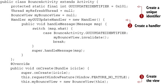
Following these basic steps, first we’ll create a class that uses Android to create a blank surface to draw on. In section 9.3.2, we’ll use OpenGL ES commands to draw a square and an animated cube on the surface. To start, open a new project called OpenGLSquare and create an Activity called OpenGLSquare, as shown in the following listing.
Listing 9.15. OpenGLSquare.java

Listing 9.15 will generate an empty black screen. Everything in this listing is code you need to draw and manage any OpenGL ES visualization.
First, we import all our needed classes. Then we implement an inner class, which will handle everything about managing a surface:
creating it, changing it, or deleting it. We extend the class SurfaceView and implement the SurfaceHolder interface, which allows us to get information back from Android when the surface changes, such as when someone resizes it
![]() . With Android, all this has to be done asynchronously; you can’t manage surfaces directly.
. With Android, all this has to be done asynchronously; you can’t manage surfaces directly.
Next, we create a thread to do the drawing ![]() and create an init method that uses the SurfaceView class’s getHolder method to get access to the SurfaceView and add a callback to it via the addCallBack method
and create an init method that uses the SurfaceView class’s getHolder method to get access to the SurfaceView and add a callback to it via the addCallBack method ![]() . Now we can implement surfaceCreated, surfaceChanged, and surfaceDestroyed, which are all methods of the Call-back class and are fired on the appropriate condition of change in the Surface’s state.
. Now we can implement surfaceCreated, surfaceChanged, and surfaceDestroyed, which are all methods of the Call-back class and are fired on the appropriate condition of change in the Surface’s state.
Now that all the Callback methods are implemented, we’ll create a thread to do all our drawing ![]() . Before we can draw anything though, we need to create an OpenGL ES Context
. Before we can draw anything though, we need to create an OpenGL ES Context ![]() and create a handler to the surface
and create a handler to the surface ![]() so that we can use the OpenGL Context’s method to act on the surface via the handle
so that we can use the OpenGL Context’s method to act on the surface via the handle ![]() . Now we can finally draw something, although in the drawFrame method
. Now we can finally draw something, although in the drawFrame method ![]() we aren’t doing anything.
we aren’t doing anything.
If you were to run the code right now, all you’d get would be an empty window, but what we’ve generated so far will appear in some form or another in any OpenGL ES application you make on Android. Typically, you would break up your code so that an Activity class starts your code and another class implements your custom View. Yet another class might implement your SurfaceHolder and Callback and provide all the methods for detecting changes to the surface, as well as the actual drawing of your graphics in a thread. Finally, you might have another class for whatever code represents your graphics.
In the next section, we’ll look at how to draw a square on the surface and how to create an animated cube.
9.3.2. Drawing a rectangle with OpenGL ES
In our next example, you’ll use OpenGL ES to create a simple drawing, a rectangle, using OpenGL primitives, which are pixels, polygons, and triangles. When you draw the square, you’ll use a primitive called the GL_Triangle_Strip, which takes three vertices (the x, y, and z points in an array of vertices) and draws a triangle. The last two vertices become the first two vertices for the next triangle, with the next vertex in the array being the final point. This process repeats for as many vertices as there are in the array, and it generates something like figure 9.5, where two triangles are drawn.
Figure 9.5. How two triangles are drawn from an array of vertices

OpenGL supports a small set of primitives, shown in table 9.1, that allow you to build anything using simple geometric shapes, from a rectangle to 3D models of animated characters.
Table 9.1. OpenGL primitives and their descriptions
|
Description |
|
|---|---|
| GL_LINE_LOOP | Draws a continuous set of lines. After the first vertex, it draws a line between every successive vertex and the vertex before it. Then it connects the start and end vertices. |
| GL_LINE_STRIP | Draws a continuous set of lines. After the first vertex, it draws a line between every successive vertex and the vertex before it. |
| GL_LINES | Draws a line for every pair of vertices given. |
| GL_POINTS | Places a point at each vertex. |
| GL_TRIANGLE_FAN | After the first two vertices, every successive vertex uses the previous vertex and the first vertex to draw a triangle. This flag is used to draw cone-like shapes. |
| GL_TRIANGLE_STRIP | After the first two vertices, every successive vertex uses the previous two vertices to draw a triangle. |
| GL_TRIANGLES | For every triplet of vertices, it draws a triangle with corners specified by the coordinates of the vertices. |
In the next listing, we use an array of vertices to define a square to paint on our surface. To use the code, insert it directly into the code for listing 9.15, immediately below the commented line // do whatever drawing here.
Listing 9.16. OpenGLSquare.java

This code is dense with OpenGL commands. The first thing we do is clear the screen using glClear, which you want to do before every drawing. Then we build the array that’ll represent the set of vertices that make up our
square. As we explained before, we’ll be using the OpenGL primitive GL_TRANGLE_STRIP to create the rectangle shown in figure 9.5, where the first set of three vertices (points 1, 2, and 3) represent the first triangle. The last vertex represents the
third vertex (point 4) in the second triangle, which reuses vertices 2 and 3 from the first triangle as its first two to make
the triangle described by points 2, 3, and 4. To put it more succinctly, Open GL takes one triangle and flips it over on its
third side (in this case, the hypotenuse). We then create a buffer to hold that same square data ![]() . We also tell the system that we’ll be using a GL_PROJECTION for our matrix mode, which is a type of matrix transformation that’s applied to every point in the matrix stack.
. We also tell the system that we’ll be using a GL_PROJECTION for our matrix mode, which is a type of matrix transformation that’s applied to every point in the matrix stack.
The next things we do are more related to setup. We load the identity matrix and then use the gluOrtho2D(GL10 gl, float left, float right, float bottom, float top) command to set the clipping planes that are mapped to the lower-left and upper-right corners of the window ![]() .
.
Now we’re ready to start drawing our image. First, we use the glVertexPointer(int size, int type, int stride, pointer to array) method, which indicates the location of vertices for our triangle strip. The method has four attributes: size, type, stride, and pointer. The size attribute specifies the number of coordinates per vertex (for example, a 2D shape might ignore the z axis and use only two
coordinates per vertex), type defines the data type to be used (GL_BYTE, GL_SHORT, GL_FLOAT, and so on) ![]() , stride specifies the offset between consecutive vertices (how many unused values exist between the end of the current vertex and
the beginning of the next), and pointer is a reference to the array. Though most drawing in OpenGL ES is performed by using various forms of arrays such as the vertex
array, they’re all disabled by default to save system resources. To enable them, we use the OpenGL command glEnableClientState(array type), which accepts an array type; in our case the type is GL_VERTEX_ARRAY.
, stride specifies the offset between consecutive vertices (how many unused values exist between the end of the current vertex and
the beginning of the next), and pointer is a reference to the array. Though most drawing in OpenGL ES is performed by using various forms of arrays such as the vertex
array, they’re all disabled by default to save system resources. To enable them, we use the OpenGL command glEnableClientState(array type), which accepts an array type; in our case the type is GL_VERTEX_ARRAY.
Finally, we use the glDrawArrays function to render our arrays into the OpenGL primitives and create our simple drawing. The glDrawArrays(mode, first, count) function has three attributes: mode indicates which primitive to render, such as GL_TRIANGLE_STRIP; first is the starting index of the array, which we set to 0 because we want it to render all the vertices in the array; and count specifies the number of indices to be rendered, which for us is 4.
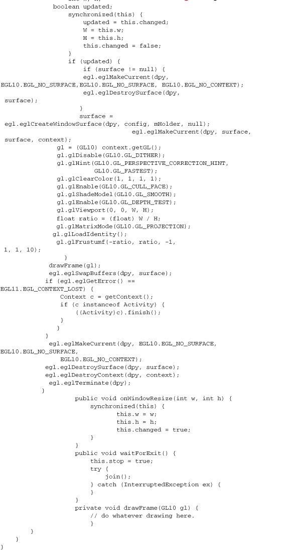
Now if you run the code, you should see a simple blue rectangle on a white surface, like the one in figure 9.6. It isn’t particularly exciting, but you would need most of the code you used for this example for any OpenGL project.
Figure 9.6. A simple rectangle drawn on our surface using OpenGL ES
There you have it—your first graphic in OpenGL ES. Now we’re going to do something way more interesting. In our next example, you’re going to create a 3D cube with different colors on each side, then rotate it in space.
9.3.3. Three-dimensional shapes and surfaces with OpenGL ES
In this section, we’re going to use much of the code from the previous example, but we’re going to extend it to create a 3D cube that rotates. We’ll examine how to introduce perspective to your graphics to give the illusion of depth.
Depth works in OpenGL by using a depth buffer, which contains a depth value for every pixel, in the range 0 to 1. The value represents the perceived distance between objects and your viewpoint; when two objects’ depth values are compared, the value closer to 0 will appear in front on the screen. To make use of depth in our program, we need to first enable the depth buffer by passing GL_DEPTH_TEST to the glEnable method. Next, we need to use glDepthFunc to define how values are compared. For our example, we’re going to use GL_LEQUAL, defined in table 9.2, which tells the system to show objects with a lower depth value in front of other objects.
Table 9.2. Flags for determining how values in the depth buffer are compared
|
Flag |
Description |
|---|---|
| GL_ALWAYS | Always passes |
| GL_EQUAL | Passes if the incoming depth value is equal to the stored value |
| GL_GEQUAL | Passes if the incoming depth value is greater than or equal to the stored value |
| GL_GREATER | Passes if the incoming depth value is greater than the stored value |
| GL_LEQUAL | Passes if the incoming depth value is less than or equal to the stored value |
| GL_LESS | Passes if the incoming depth value is less than the stored value |
| GL_NEVER | Never passes |
| GL_NOTEQUAL | Passes if the incoming depth value is not equal to the stored value |
When you draw a primitive, the depth test occurs. If the value passes the test, the incoming color value replaces the current one.
The default value is GL_LESS. You want the value to pass the test if the values are equal as well. Objects with the same z value will display, depending on the order in which they were drawn. We pass GL_LEQUAL to the function.
One important part of maintaining the illusion of depth is providing perspective. In OpenGL, a typical perspective is represented by a viewpoint with near and far clipping planes and top, bottom, left, and right planes, where objects that are closer to the far plane appear smaller, as in figure 9.7.
Figure 9.7. In OpenGL, a perspective is made up of a viewpoint and near (N), far (F), left (L), right (R), top (T), and bottom (B) clipping planes.

OpenGL ES provides a function called gluPerspective(GL10 gl, float fovy, float aspect, float zNear, float zFar) with five parameters (see table 9.3) that lets you easily create perspective.
Table 9.3. Parameters for the gluPerspective function
|
Parameter |
Description |
|---|---|
| aspect | The aspect ratio that determines the field of view in the x direction. The aspect ratio is the ratio of x (width) to y (height). |
| fovy | Field of view angle in the y direction, in degrees, |
| gl | GL10 interface. |
| zFar | The distance from the viewer to the far clipping plane. This value is always positive. |
| zNear | The distance from the viewer to the near clipping plane. This value is always positive. |
To demonstrate depth and perspective, you’re going to create a project called OpenGLCube and copy and paste the code from listing 9.15 into the OpenGLCube-Activity.
Now add two new variables to your code, shown in the following listing, right at the beginning of the DrawSurfaceView inner class.
Listing 9.17. OpenGLCubeActivity.java
class DrawingSurfaceView extends SurfaceView implements
SurfaceHolder.Callback  {
    public SurfaceHolder mHolder;
    float xrot = 0.0f;
    float yrot = 0.0f;
We’re going to use xrot and yrot variables later in our code to govern the rotation of our cube.
Next, right before the method, add a new method called makeFloatBuffer, as in the following listing.
Listing 9.18. OpenGLCubeActivity.java
protected FloatBuffer makeFloatBuffer(float[] arr) {
            ByteBuffer bb = ByteBuffer.allocateDirect(arr.length*4);
            bb.order(ByteOrder.nativeOrder());
            FloatBuffer fb = bb.asFloatBuffer();
            fb.put(arr);
            fb.position(0);
            return fb;
}
This float buffer is the same as the one in listing 9.16, but we’ve abstracted it from the drawFrame method so we can focus on the code for rendering and animating our cube.
Next, copy and paste the code in the following listing into the drawFrame method. Note you’ll also need to update your drawFrame call in the following way:
drawFrame(gl, w, h);
Listing 9.19. OpenGLCubeActivity.java


This listing doesn’t contain much new code. First, we describe the vertices for a cube, which is built in the same way as
our simple rectangle in listing 9.16 (using triangles). Next, we set up the float buffer for our vertices ![]() and enable the depth function
and enable the depth function ![]() and perspective function
and perspective function ![]() to provide a sense of depth. Note that with our glu-Perspective we passed 45.0f (45 degrees) to give a more natural viewpoint.
to provide a sense of depth. Note that with our glu-Perspective we passed 45.0f (45 degrees) to give a more natural viewpoint.
Next, we use the GLU.gluLookAt(GL10 gl, float eyeX, float eyeY, float eyeZ, float centerX, float centerY, float centerZ, float upX, float upY,
float upZ) function to move the position of our view without having to modify the projection matrix directly. When we’ve established
our view position, we turn on smooth shading for the model and rotate the cube around the x and y axes ![]() . Then we draw the cube sides and increment the rotation so that on the next iteration of draw, the cube is drawn at a slightly
different angle
. Then we draw the cube sides and increment the rotation so that on the next iteration of draw, the cube is drawn at a slightly
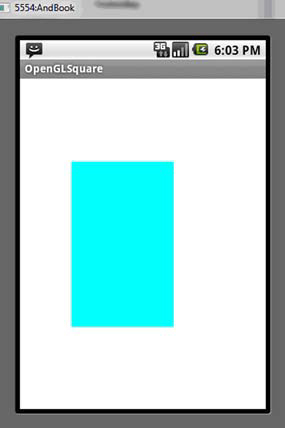
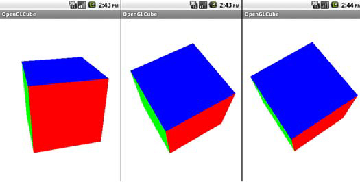
different angle ![]() . If you run the code, you should now see a rotating 3D cube like the one shown in figure 9.8.
. If you run the code, you should now see a rotating 3D cube like the one shown in figure 9.8.
Figure 9.8. A 3D cube rotating in space
Note
You can try experimenting with the fovy value to see how changing the angle affects the display of the cube.
You’ve done a lot in this section, starting with creating a simple OpenGL ES context in which you can develop your OpenGL ES applications. Next, you learned how to build shapes using OpenGL ES by creating multiple triangles. Then, you learned how to realize this in three dimensions while incorporating it into a simple example. You accomplished much of this without diving deep into OpenGL ES, which is definitely nontrivial, but the good news is if you’re serious about doing 3D graphics on Android, it’s definitely possible. Because Android provides excellent support for OpenGL ES, you can find plenty of tutorials and references on the internet or at your local bookstore.
9.4. Summary
In this chapter, we’ve lightly touched on a number of topics related to Android’s powerful graphics features. First, we looked at how you can use both Java and XML with the Android Graphics API to describe simple shapes. Next, we looked at how you can use Android’s frame-by-frame XML to create an animation. You also learned how to use more standard pixel manipulation to provide the illusion of movement through Java and the Graphics API. Finally, we delved lightly into Android’s support of OpenGL ES. We looked at how to create an OpenGL context, and then built a shape in that context. Finally, you built a 3D animated cube.
Graphics and visualizations are large and complex topics, easily filling a whole book. Yet, because Android uses open and well-defined standards and supports an excellent API for graphics, it should be easy for you to use Android’s documentation, API, and other resources, such as Manning’s Java 3D Programming by Daniel Selman, to develop anything from a new drawing program to complex games.
In the next chapter, we’ll move from graphics to working with multiple media. We’ll explore working with audio and video to lay the groundwork for making rich multimedia applications.