The objectives of this chapter are to:
Provide an overview of the tools used when developing a Microsoft Dynamics AX 2009 enterprise resource planning (ERP) application with MorphX.
Share tips and tricks on how to use the MorphX tools efficiently.
Demonstrate how to personalize and extend the MorphX tools.
Dynamics AX includes a set of tools, the MorphX development tools, that allow developers to build and modify Dynamics AX business applications. Each feature of a business application uses the application model elements described in Chapter 2. The MorphX tools enable developers to create, view, modify, and delete the application model elements, which contain metadata, structure (ordering and hierarchies of elements), properties (key and value pairs), and X++ code. For example, a table element includes the name of the table, the properties set for the table, the fields, the indices, the relations, the methods, and so on.
This chapter describes the most commonly used tools and offers some tips and tricks for working with them. You can find additional information and an overview of other MorphX tools in the MorphX Development Tools section of the Microsoft Dynamics AX software development kit (SDK) 2009 on MSDN.
Tip
To enable the development mode of Dynamics AX 2009, press Ctrl+Shift+D. Ctrl+Shift+D is a toggle key that also returns you to content mode.
Table 3-1 lists the MorphX tools that are discussed in this chapter.
Table 3-1. MorphX Tools
Tool | Use This Tool To: |
|---|---|
Application Object Tree (AOT) | Start development activities. The AOT is the main entry point for all development activities. It is the repository for all elements that together comprise the business application. You can use the AOT to invoke the other tools and to browse and create elements. |
Project Designer | Group related elements into projects. |
Property sheet | Inspect and modify properties of elements. The property sheet shows key and value pairs. |
X++ Code Editor | Inspect and write X++ source code. |
Label Editor | Create and inspect localizable strings. |
Visual Form Designer and the Visual Report Designer | Design forms and reports in a What You See Is What You Get (WYSIWYG) fashion. |
Compiler | Compile X++ code into an executable format. |
Best Practices tool | Automatically detect defects in both your code and your elements. |
Debugger | Find bugs in your X++ code. |
Reverse Engineering tool | Generate Microsoft Office Visio Unified Modeling Language (UML) and Entity Relationship Diagrams (ERDs) from elements. |
Table Browser tool | View the contents of a table directly from the table element. |
Find tool | Search for code or metadata patterns in the AOT. |
Compare tool | See a line-by-line comparison of two versions of the same element. |
Cross-reference tool | Determine where an element is used. |
Version Control tool | Track all changes to elements and see a full revision log. |
Unit Test tool | Build automated tests that can exercise your code and detect regressions. |
You can access these development tools from the following places:
The Development Tools submenu on the Tools menu. From the Microsoft Dynamics AX drop-down menu, point to Tools, and then point to Development Tools.
The context menu on elements in the AOT.
Note
The Microsoft Dynamics AX SDK contains valuable developer documentation and is updated frequently. Find it in the Microsoft Dynamics AX Developer Center on msdn.microsoft.com.
You can personalize the behavior of many MorphX tools by clicking Options on the Tools menu. Figure 3-1 shows the Options dialog box.

The AOT is the main entry point to MorphX and is the repository explorer for all metadata. You can open the AOT by clicking the AOT icon on the toolbar or by pressing Ctrl+D. The AOT icon looks like this:
As the name implies, the AOT is a tree view. The root of the AOT contains the element categories, such as Classes, Tables, and Forms. Some elements are grouped into subcategories to provide a better structure. For example, Tables, Maps, Views, and Extended Data Types reside under Data Dictionary, and all Web-related elements are found under Web. Figure 3-2 shows the AOT.

You can navigate the AOT by using the arrow keys on the keyboard. Pressing the Right arrow key expands a node if it has any children.
Elements are ordered alphabetically. Because thousands of elements exist, understanding the naming conventions and adhering to them is important to effectively using the AOT.
All element names in the AOT follow this structure:
<Business area name> + <Business area description> + <Action performed or type of content>
In this naming convention, similar elements are placed next to each other. The business area name is also often referred to as the prefix. Prefixes are commonly used to indicate the team responsible for an element.
Table 3-2 contains a list of the most common prefixes and their descriptions.
Table 3-2. Common Prefixes
Prefix | Description |
|---|---|
Ax | Dynamics AX typed data source |
Axd | Dynamics AX business document |
BOM | Bill of material |
COS | Cost accounting |
Cust | Customer |
HRM | Human resources management |
Invent | Inventory management |
JMG | Shop floor control |
KM | Knowledge management |
Ledger | General ledger |
PBA | Product builder |
Prod | Production |
Proj | Project |
Purch | Purchase |
Req | Requirements |
Sales | Sales |
SMA | Service management |
SMM | Sales and marketing management |
Sys | Application frameworks and development tools |
Tax | Tax engine |
Vend | Vendor |
Web | Web framework |
WMS | Warehouse management |
Tip
When creating new elements, make sure to follow the recommended naming conventions. Any future development and maintenance will be much easier.
The Project Designer, described in detail later in this chapter, provides an alternative view of the information organized by the AOT.
You can create new elements in the AOT by right-clicking the element category node and selecting New <Element Name>, as shown in Figure 3-3.

Objects are given automatically generated names when they are created. However, you should replace the default names with new names in accordance with the naming conventions.
Each node in the AOT has a set of properties and either subnodes or X++ code. You can use the property sheet (shown in Figure 3-9) to inspect or modify properties, and you can use the X++ code editor (shown in Figure 3-11) to inspect or modify X++ code.
The order of the subnodes can play a role in the semantics of the element. For example, the tabs on a form display in the order in which they are listed in the AOT. You can change the order of nodes by selecting a node and pressing the Alt key while pressing the Up or Down arrow key.
A red vertical line next to an element name marks it as modified and unsaved, or dirty, as shown in Figure 3-4.

A dirty element is saved in the following situations:
The element is executed.
The developer explicitly invokes the Save or Save All action.
Autosave takes place. You specify the frequency of autosave in the Options dialog box accessible from the Tools menu.
If several developers modify elements simultaneously in the same installation of Dynamics AX, each developer’s local elements could become out of sync with the latest version. To ensure that the local versions of remotely changed elements are updated, an autorefresh thread runs in the background. This autorefresh functionality eventually updates all changes, but you might want to explicitly force a refresh. You do this by right-clicking the element you want to restore and then selecting Restore. This action refreshes both the on-disk and the in-memory versions of the element. The following is a less elegant way of ensuring that the latest elements are used:
Close the Dynamics AX client to clear in-memory elements.
Close the Dynamics Server service on the Application Object Server (AOS) to clear in-memory elements.
Delete the application object cache files (*.auc) from the Local Application Data folder (located in Documents and Settings<User>Local SettingsApplication Data) to remove the on-disk elements.
Each node in the AOT contains a set of available actions. You can access these actions from the context menu, which you can open by right-clicking the node in question.
Here are two facts to remember about actions:
The actions available depend on the type of node you select.
You can select multiple nodes and perform actions simultaneously on all the nodes selected.
A frequently used action is Open New Window, which is available for all nodes. It opens a new AOT window with the current nodes as the root. We used this action to create the screen capture of the CustTable element shown in Figure 3-4. Once you open a new AOT window, you can drag elements into the nodes, saving time and effort when you’re developing an application.
You can extend the list of available actions on the context menu. You can create custom actions for any element in the AOT by using the features provided by MorphX. In fact, all actions listed on the Add-Ins submenu are implemented in MorphX by using X++ and the MorphX tools.
You can enlist a class as a new add-in by following this procedure:
Create a new menu item and give it a meaningful name, a label, and Help text.
Set the menu item’s Object Type property to Class.
Set the menu item’s Object property to the name of the class to be invoked by the add-in.
Drag the menu item to the SysContextMenu menu.
If you want the action available only for certain nodes, you need to modify the verifyItem method on the SysContextMenu class.
When you modify an element from a lower layer, a copy of the element is placed in the current layer. All elements in the current layer appear in bold type (as shown in Figure 3-5), which makes it easy to recognize changes. For a description of the layer technology, see the section "Application Model Layering System" in Chapter 1.

You can use the Application Object Layer setting in the Options dialog box to personalize the layer information shown in the AOT. Figure 3-5 shows a class with the option set to All Layers. As you can see, each method is suffixed with information about the layers in which it is defined, such as sys, var, and usr. If an element exists in several layers, you can right-click it and select Layers to access its versions from lower layers. We highly recommend the All Layers setting during code upgrade because it provides a visual representation of the layer dimension directly in the AOT.
For a fully customizable overview of the elements, you can use projects. In a project, elements can be grouped and structured according to the developer’s preference. The Project Designer is a powerful alternative to the AOT because you can collect all the elements needed for a feature in one project.
You open the Project Designer by clicking the Project button on the toolbar. Figure 3-6 shows the Project Designer and its Private and Shared projects.

Except for its structure, the Project Designer behaves exactly like the AOT. Every element in a project is also present in the AOT.
When you create a new project, you must decide whether it should be private or shared among all developers. You can’t set access requirements on shared projects. You can make a shared project private (and a private project shared) by dragging it from the shared category into the private category.
Note
Central features of Dynamics AX 2009 are captured in shared projects to provide an overview of all the elements in a feature. No private projects are included with the application.
You can specify a startup project in the Options dialog box. If specified, the chosen project automatically opens when Dynamics AX is started.
Projects can be automatically generated in several ways—from using group masks to customizing special project types—to make working with them easier. We discuss the various ways to automatically generate projects in the sections that follow.
Groups are folders in a project. When you create a group, you can have its contents be automatically generated by setting the ProjectGroupType property (All is an option) and a regular expression as the GroupMask property. The contents of the group are created automatically and kept up to date as elements are created, deleted, and renamed. Using group masks ensures that your project is always current, even when elements are created directly in the AOT.
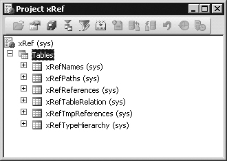
Figure 3-7 shows the ProjectGroupType property set to Tables and the GroupMask property set to <xRef on a project group. All table names starting with xRef (the prefix for the Cross-reference tool) will be included in the project group.

Figure 3-8 shows the resulting project when the settings from Figure 3-7 are used.
You can also generate a project based on a filter. Because all elements in the AOT persist in a database format, you can use a query to filter elements and have the results presented in a project. You create a project filter by clicking the Filter button on the project’s toolbar. Depending on the complexity of the query, a project can be generated instantly or might take several minutes.
Filters allow you to create projects containing the following kinds of elements:
Elements created or modified within the last month
Elements created or modified by a named user
Elements from a particular layer
Several development tools, such as the Wizard wizard, produce projects containing elements the wizard creates. The result of running the Wizard wizard is a new project that includes a form, a class, and a menu item—all the elements comprising the newly created wizard.
You can also use several other wizards, such as the Report Wizard and the Class Wizard, to create projects. You can access these wizards from the Microsoft Dynamics AX drop-down menu by clicking ToolsDevelopment ToolsWizards.
You can compare all the elements in one layer with the elements in another layer, called the reference layer. If an element exists in both layers, and the definitions of the element are different or the element doesn’t exist in the reference layer, the element will be added to the resulting project. You can compare layers by clicking ToolsDevelopment ToolsCode Upgrade from the Microsoft Dynamics AX drop-down menu.
When you upgrade from one version of Dynamics AX to another or install a new service pack, you need to deal with any new elements that are introduced and existing elements that have been modified. These changes might conflict with customizations you’ve implemented in a higher layer.
The Create Upgrade Project feature makes a three-way comparison to establish whether an element has any upgrade conflicts. It compares the original version with both the customized version and the updated version. If a conflict is detected, the element is added to the project.
The resulting project provides a list of elements to update based on upgrade conflicts between versions. You can use the Compare tool, described later in this chapter, to see the conflicts in each element. Together, these features provide a cost-effective toolbox to use when upgrading. For more information about upgrading code, see Chapter 18.
You can create upgrade projects by clicking ToolsDevelopment ToolsCode UpgradeDetect Code Upgrade conflicts from the Microsoft Dynamics AX drop-down menu.
When you create a new project, you can specify a project type. So far in this chapter, we’ve limited our discussion to standard projects. Two specialized project types are also provided in Dynamics AX:
Test project. Project used to group a set of classes for unit testing
Help Book project. Project used for the table of contents in the online Help system
You can create a custom specialized project by creating a new class that extends the ProjectNode class. Specialized projects allow you to control the structure, icons, and actions available to the project.
Properties are an important part of the metadata system. Each property is a key and value pair. The property sheet allows you to inspect and modify properties of elements.
Open the property sheet by pressing Alt+Enter or by clicking the Properties button. The property sheet automatically updates itself to show properties for any element selected in the AOT. You don’t have to manually open the property sheet for each element; you can simply leave it open and browse the elements. Figure 3-9 shows the property sheet for a TaxSpec class. The two columns are the key and value pairs for each property.

Figure 3-10 shows the Categories tab for the class shown in Figure 3-9. Here, related properties are categorized. For elements with many properties, this view can make it easier to find the right property.

Read-only properties appear in gray. Just like files in the file system, elements contain information about who created them and when they were modified. The Microsoft build process ensures that all elements that ship from Microsoft have the same time and user stamp.
The default sort order places related properties near each other. Categories were introduced in an earlier version of Dynamics AX to make finding properties easier, but you can also sort properties alphabetically by setting a parameter in the Options dialog box. (Thanks to Erik Damgaard, founder of Damgaard Data, the default sorting order is retained in the current version for developers familiar with the original layout of properties.)
You can dock the property sheet on either side of the screen by right-clicking the title bar. Docking ensures that the property sheet is never hidden behind another tool.
You write all X++ code with the X++ code editor. You open the editor by selecting a node in the AOT and pressing Enter. The editor contains two panes. The left pane shows the methods available, and the right pane shows the X++ code for the selected method, as shown in Figure 3-11.

The X++ code editor is a basic text editor that supports color coding and IntelliSense.
Navigation and editing in the X++ code editor use standard shortcuts, as described in Table 3-3.
Table 3-3. X++ Code Editor Shortcut Keys
Action | Shortcut | Description |
|---|---|---|
Show Help window | F1 | Opens context-sensitive Help for the type or method currently selected in the editor. |
Go to next error message | F4 | Opens the editor and positions the cursor at the next compilation error, based on the contents of the compiler output window. |
Execute current element | F5 | Starts the current form, report, or class. |
Compile | F7 | Compiles the current method. |
Toggle a breakpoint | F9 | Sets or removes a breakpoint. |
List enumerations | F11 | Provides a drop-down list of all enumerations available in the system. |
List reserved words | Shift+F2 | Provides a drop-down list of all reserved words in X++. |
List built-in functions | Shift+F4 | Provides a drop-down list of all built-in functions available in X++. |
Run an editor script | Alt+R | Lists all available editor scripts and lets you select one to execute (such as Send to mail recipient). |
Open the Label Editor | Ctrl+Alt+Spacebar | Opens the Label Editor and searches for the selected text. |
Show parameter information or IntelliSense list members | Ctrl+Spacebar | Shows parameter information as a ScreenTip or shows members in a dropdown list. |
Go to implementation (drill down in code) | Ctrl+Shift+Spacebar | Goes to the implementation of the selected method. Highly useful for fast navigation. |
Go to the next method | Ctrl+Tab | Sets focus on the next method in the editor. |
Go to the previous method | Ctrl+Shift+Tab | Sets focus on the previous method in the editor. |
Enable block selection | Alt+O | Enables block selection, instead of the default line selection. |
The X++ code editor contains a set of editor scripts that you can invoke by clicking the Script button on the X++ Code Editor toolbar or by pressing Alt+R. Editor scripts provide functionality such as the following:
Send to mail recipient.
Send to file.
Comment or uncomment code.
Check out element, if version control is enabled.
Generate code for standard code patterns.
Open the AOT for the element that owns the method.
Note
Code generation allows you to create, in a matter of minutes, a new class with the right constructor method and the right encapsulation of member variables by using parm methods. Parm methods (parm is short for "parameter") are used as simple property getters/setters on classes. Naturally, code generation is carried out in accordance with X++ best practices.
The list of editor scripts is extendable. You can create your own scripts by adding new methods to the EditorScripts class.
The term label in Dynamics AX simply refers to a localizable text resource. Text resources are used throughout the product as messages to the user, form control labels, column headers, Help text in the status bar, captions on forms, and text on Web forms, to name just a few places. Labels are localizable, meaning that they can be translated into most languages. Because the space requirement for displaying text resources typically depends on the language, you might fear that the actual user interface must be manually localized as well. However, with IntelliMorph technology, the user interface is dynamically rendered and honors any space requirements imposed by localization.
The technology behind the label system is simple. All text resources are kept in a Unicode-based label file that must have a three-letter identifier. The label file is located in the application folder (Program FilesMicrosoft Dynamics AX50ApplicationApplStandard) and follows this naming convention:
Ax<Label file identifier><Locale>.ALD
The following are two examples, the first showing U.S. English and the second a Danish label file:
Axsysen-us.ALD
Axtstda.ALD
Each text resource in the label file has a 32-bit integer label ID, label text, and an optional label description. The structure of the label file is very simple:
@<Label file identifier><Label ID> <Label text>
[Label description]
Figure 3-12 shows an example of a label file.

This simple structure allows for localization outside Dynamics AX using third-party tools.
After the localized label files are in place, the user can choose a language in the Options dialog box. When the language is changed, the user must close and restart the Dynamics AX client.
You can create new label files by using the Label File Wizard, which you access from the Microsoft Dynamics AX drop-down menu by clicking ToolsDevelopment ToolsWizardsLabel File Wizard. The wizard guides you through the steps for adding a new label file or a new language to an existing label file. After you run the wizard, the label file is ready to use.
Note
You can use any combination of three letters when naming a label file, and you can use any label file from any layer. A common misunderstanding is that the label file identifier must be the same as the layer in which it is used. This misunderstanding is caused by the Microsoft label file identifiers. Dynamics AX ships with a SYS layer and a label file named SYS; service packs contain a SYP layer and a label file named SYP. This naming standard was chosen because it is simple, easy to remember, and easy to understand. Dynamics AX doesn’t impose any limitations on the label file name.
The following are tips for working with label files:
When naming a label file, choose a three-letter ID that has a high chance of being unique, such as your company’s initials. Don’t choose the name of the layer, such as VAR or USR. Eventually, you’ll likely merge two separately developed features into the same installation, a task that will be more difficult if the label files collide.
Feel free to reference labels in the Microsoft-provided label files, but avoid making changes to labels in these label files, because they are updated with each new version of Dynamics AX.
You use the Label Editor to create new labels. You can start it using any of the following procedures:
Clicking ToolsDevelopment ToolsLabelLabel Editor from the Microsoft Dynamics AX drop-down menu
Clicking the Lookup Label/Text button on the X++ code editor toolbar
Clicking the Lookup button on text properties in the property sheet
The Label Editor (shown in Figure 3-13) allows you to find existing labels. Reusing a label is often preferable to creating a new one. You can create a new label by pressing Ctrl+N or by clicking the New button.

In addition to allowing you to find and create new labels, the Label Editor can also show where a label is used. It also logs any changes to each label.
The following are tips to consider when creating and reusing labels:
When reusing a label, make sure that the label meaning is what you intend it to be in all languages. Some words are homonyms, meaning words that have many meanings, and they naturally translate into many different words in other languages. For example, the English word can is both a verb and a noun. The description column describes the intended meaning of the label.
When creating new labels, make sure to use complete sentences or other stand-alone words or phrases in each label. Don’t construct complete sentences by concatenating labels with one or few words, because the order of words in a sentence differs from one language to another.
In the MorphX design environment, labels are referenced in the format @<LabelFileIdentifier> <LabelID>. If you don’t want a label reference to automatically convert to the label text, you can use the literalStr function. When a placeholder is needed to display the value of a variable, you can use the strFmt function and a string containing %n, where n> = 1. Placeholders can also be used within labels. The following code shows a few examples.
The following are some best practices to consider when referencing labels from X++:
You should always create user interface text by using a label. When referencing labels from X++ code, use double quotation marks.
You should never create system text such as file names by using a label. When referencing system text from X++ code, use single quotation marks. You can place system text in macros to make it reusable.
Using single and double quotation marks to differentiate between system text and user interface text allows the Best Practices tool to find and report any hard-coded user interface text. The Best Practices tool is described in depth later in this chapter.
MorphX has two visual designers, one for forms and one for reports, that allow you to drag controls onto the design surface in WYSIWYG fashion. IntelliMorph determines the actual position of the controls, so you can’t place them precisely.
You can override these layout restrictions by changing property values, such as Top, Left, Height, and Width, from Auto to a fixed value, allowing the visual designers to lay out the controls. However, doing so interferes with the automated layout attempted by IntelliMorph, which means that there is no guarantee that your forms and reports will display well when translated, configured, secured, and personalized.
It is a best practice to let IntelliMorph control all the layout. (More detailed information about IntelliMorph is in Chapter 13.) Most forms and reports that ship with Dynamics AX are designed by using the AOT. When the visual designer is opened, a tree structure of the design is displayed, making it fairly simple to add new controls to the design. You can either drag fields or field groups from the data source to the design or right-click the design and choose New Control.
Note
IntelliMorph and MorphX treat form and report designs as hierarchical structures. A control can be next to another control or inside a group control. This arrangement makes a lot of sense for business applications. If you require controls to be on top of one another, you must use absolute pixel positions. The order of the controls in the AOT mandates the z-order—that is, the order in which controls are virtually stacked in the display.
You can use a Report Wizard, accessed from the Microsoft Dynamics AX drop-down menu at ToolsDevelopment ToolsWizards, to help you create reports. The wizard guides you through the process step by step, allowing you to specify data sources, sorting, grouping, layout, and other settings before producing a report in the AOT. You can read more about developing reports in Chapter 11.
The designers can be helpful tools for learning how the IntelliMorph layout scheme works. If you have the Visual Form Designer open when you start designing a form, you immediately see what the form will look like, even when it is modified in the AOT. In fact, after creating a few forms, you’ll probably feel so confident of the power of IntelliMorph and the effectiveness of designing forms in the AOT that you’ll only rarely use the Visual Form Designer.
You open the Visual Form Designer by right-clicking a form’s design in the AOT and selecting Edit. The designer is shown in design mode in Figure 3-14. Next to the form is a toolbar with all the available controls, which can be dragged onto the form’s surface. You can also see the property sheet showing the selected control’s properties.

One interesting form that overrides IntelliMorph is the form tutorial_Form_freeform. Figure 3-15 shows how a scanned bitmap of a payment form is used as a background image for the form, and the controls positioned where data entry is needed.

The majority of MorphX reports fall into two categories—internal and external. Requirements for reports used internally in a company are often more relaxed than requirements for external reports. External reports are often part of the company’s face to the outside world. An invoice report is a classic example of an external report.
Leveraging the features of IntelliMorph, internal reports typically follow an autodesign that allows the consumer of the report to add and remove columns from the report and control its orientation, font, and font size.
External reports typically use a generated design, which effectively overrides IntelliMorph. So for external reports, the Visual Report Designer is clearly preferable. Often, external reports are printed on preprinted paper containing, for example, the company’s letterhead, so the ability to easily control the exact position of each control is essential.
You create a generated design from an autodesign by right-clicking a design node of a report in the AOT and selecting Generate Design. You can open the Visual Report Designer by right-clicking a generated design and selecting Edit. As shown in Figure 3-16, each control can be moved freely, and new controls can be added.

Notice the zoom setting in the lower-right corner of Figure 3-16. This setting allows you to get a close-up view of the report and, with a steady hand, position each control exactly where you want it.
The rendering subsystem of the report engine can print only generated designs because it requires all controls to have fixed positions. If a report has only an autodesign, the report engine generates a design in memory before printing.
Whenever you make a change to X++ code, you must recompile, just as you would in any other development language. You start the recompile by pressing F7 in the X++ code editor. Your code also recompiles whenever you close the editor or save a dirty element.
The compiler also produces a list of the following information:
Compiler errors. These prevent code from compiling and should be fixed as soon as possible.
Compiler warnings. These typically indicate that something is wrong in the implementation. See Table 3-4, later in this section, for a list of compiler warnings. Compiler warnings can and should be addressed. Check-in attempts with compiler warnings are rejected.
Table 3-4. Compiler Warnings
Warning Message
Level
Break statement found outside legal context
1
The new method of a derived class does not call super()
1
The new method of a derived class may not call super()
1
Function never returns a value
1
Not all paths return a value
1
Assignment/comparison loses precision
1
Unreachable code
2
Empty compound statement
3
Class names should start with an uppercase letter
4
Member names should start with a lowercase letter
4
Tasks (also known as to-dos). The compiler picks up single-line comments that start with TODO. These comments can be useful during development for adding reminders, but you should use them only in cases in which implementation can’t be completed.
For example, you might use a to-do comment when you’re waiting for a check-in from another developer. You should avoid using to-do comments just to postpone work. For a developer, there is nothing worse than debugging an issue at a customer site and finding a to-do comment indicating that the issue was already known but overlooked.
Note
Unlike other languages, X++ requires that you compile only code you’ve modified. This is because the intermediate language the compiler produces is persisted along with the X++ code and metadata. Of course, your changes can require other methods consuming your code to be changed and recompiled if, for example, you rename a method or modify its parameters. If the consumers are not recompiled, a run-time error is thrown when they are invoked. This means that you can execute your business application even when compile errors exist, as long as you don’t use the code that can’t compile. You should always compile the entire AOT when you consider your changes complete, and you should fix any compilation errors found.
Best practice deviations. The Best Practices tool carries out more complex validations. See the section "Best Practices Tool" later in this chapter for more information.
The Compiler Output dialog box provides access to everything reported during compilation, as shown in Figure 3-17. Each category of findings has a dedicated tab: Status, Errors And Warnings, Best Practices, and Tasks. Each tab contains the same information for each issue that the compiler detects—a description of the issue and its location. For example, the Status tab shows a count of the detected issues.

You can export compile results. This capability is useful if you want to share the list of issues with team members. The exported file is an HTML file that can be viewed in Microsoft Internet Explorer or re-imported into the Compiler Output dialog box in another Dynamics AX session.
In the Compiler Output dialog box, click Setup and then click Compiler to define the types of issues that the compiler should report. Compiler warnings are grouped into four levels, as shown in Table 3-4.
Constructing quality software has become a daunting task in the 21st century. Many new competencies are expected of the developer, and mastering them fully and at all times is nearly impossible. Today you must write code conforming to many technical requirements, including security, localization, internationalization, customization, performance, accessibility, reliability, scalability, compatibility, supportability, interoperability, and so on. The list seems to grow with each software revision, and keeping up with all of these competencies is increasingly difficult.
Microsoft Dynamics AX 2009 includes a software development kit (SDK) that explains how to satisfy these requirements when you use MorphX. You can access the SDK from the application Help menu under Developer Help. We highly recommend that you read the Developer Help section—it’s not just for novices but also for experienced developers, who will find that the content has been extensively revised for Dynamics AX 2009. The SDK is frequently refreshed with new content, so you might want to check it often on MSDN.
Among other critical information, the Developer Help section of the SDK includes an important discussion on conforming to best practices in Dynamics AX. The motivation for conforming to best practices should be obvious to anyone. Constructing code that follows proven standards and patterns can’t guarantee a project’s success, but it certainly minimizes the risk of failure. To ensure your project’s success, you should learn, conform to, and advocate best practices within your group.
The following are a few benefits of following best practices:
You avoid less-than-obvious pitfalls. Following best practices helps you avoid many obstacles, even those that surface only in border scenarios that would otherwise be difficult and time consuming to detect and test. Using best practices allows you to leverage the combined experiences of Dynamics AX expert developers.
The learning curve is flattened. When you perform similar tasks in a standard way, you are more comfortable in an unknown area of the application. Consequently, adding new resources to a project is more cost efficient, and downstream consumers of the code are able to make changes more readily.
You are making a long-term investment. Code that conforms to standards is less likely to require rework during an upgrade process, whether you’re upgrading to Dynamics AX 2009, installing service packs, or upgrading to future releases.
You are more likely to ship on time. Most of the problems you face when implementing a solution in Dynamics AX have been solved at least once before. Choosing a proven solution results in faster implementation and less regression. You can find solutions to known problems in both the Developer Help section of the SDK and the code base.
A powerful supplement to the best practices discussion in the SDK is the Best Practices tool. This tool is the MorphX version of a static code analysis tool, similar to FxCop for the Microsoft .NET Framework and PREfix and PREfast for C and C++. The Best Practices tool is embedded in the compiler, and the results are located on the Best Practices tab of the Compiler Output dialog box.
The purpose of static code analysis is to automatically detect defects in the code. The longer a defect exists, the more costly it becomes to fix—a bug found in the design phase is much cheaper to correct than a bug in shipped code running at several customer sites. The Best Practices tool allows any developer to run an analysis of his or her code and application model to ensure that it conforms to a set of predefined rules. Developers can run analysis during development, and they should always do so before implementations are tested.
The Best Practices tool displays deviations from the best practice rules, as shown in Figure 3-17. Double-clicking a line on the Best Practices tab opens the X++ code editor on the violating line of code.
The Best Practices tool includes about 350 rules, a small subset of the best practices mentioned in the SDK. You can define the best practice rules that you want to run in the Best Practice Parameters dialog box: from the Microsoft Dynamics AX drop-down menu, click ToolsOptions and then the Best Practices button.
Note
You must set the compiler error level to 4 if you want best practice rule violations to be reported. To turn off the Best Practices tool, click ToolsOptionsCompiler, and then set the diagnostic level to less than 4.
The best practice rules are divided into categories. By default, all categories are turned on, as shown in Figure 3-18.

The best practice rules are divided into three levels of severity:
Errors. The majority of the rules focus on errors. Any check-in attempt with a best practice error is rejected. You must take all errors seriously and fix them as soon as possible.
Warnings. Follow a 95/5 rule for warnings. This means that you should treat 95 percent of all warnings as errors; the remaining 5 percent constitute exceptions to the rule. You should provide valid explanations in the design document for all warnings you choose to ignore.
Information. In some situations, your implementation might have a side effect that isn’t obvious to you or the user (e.g., if you’re assigning a value to a variable but you never use the variable again). These are typically reported as information messages.
The Best Practices tool allows you to suppress errors and warnings. A suppressed best practice deviation is reported as information. This gives you a way to identify the deviation as reviewed and accepted. To identify a suppressed error or warning, place a line containing the following text just before the deviation.
Only a small subset of the best practice rules can be suppressed. Use the following guidelines for selecting which rules to suppress:
Where exceptions exist that are impossible to detect automatically, you should examine each error to ensure the correct implementation. Dangerous APIs are often responsible for such exceptions. A dangerous API is an API that can compromise a system’s security when used incorrectly. If a dangerous API is used, a suppressible error is reported. You are allowed to use some so-called dangerous APIs when you take certain precautions, such as using code access security. You can suppress the error after you apply the appropriate mitigations.
About 5 percent of all warnings are false positives and can be suppressed. Note that only warnings caused by actual code can be suppressed, not warnings caused by metadata.
After you set up the best practices, the compiler automatically runs the best practices check whenever an element is compiled. The results are displayed on the Best Practices tab in the Compiler Output dialog box.
The X++ Best Practices tool allows you to create your own set of rules. The classes used to check for rules are named SysBPCheck<ElementKind>. You call the init, check, and dispose methods once for each node in the AOT for the element being compiled.
One of the most interesting classes is SysBPCheckMemberFunction, which is called for each piece of X++ code whether it is a class method, form method, macro, or other method. For example, if developers don’t want to include their names in the source code, you can implement a best practice check by creating the following method on the SysBPCheckMemberFunction class.
To enlist the rule, make sure to call the preceding method from the check method. Compiling this sample code results in the best practice errors shown in Table 3-5.
Table 3-5. Best Practice Errors in checkUseOfNames
Message | Line | Column |
|---|---|---|
Method contains text constant: ‘Arthur’ | 4 | 27 |
Don’t use your name! | 4 | 28 |
Method contains text constant: ‘Lars’ | 4 | 37 |
Don’t use your name! | 4 | 38 |
Method contains text constant: ‘Michael’ | 4 | 45 |
Don’t use your name! | 4 | 46 |
Method contains text constant: ‘Don’t use your name!’ | 20 | 59 |
In a real-world implementation, names of developers would probably be read from a file. Make sure to cache the names to prevent the compiler from going to the disk to read the names for each method being compiled.
Like most development environments, MorphX features a debugger. The debugger is a stand-alone application, not part of the Dynamics AX shell like the rest of the tools mentioned in this chapter. As a stand-alone application, the debugger allows you to debug X++ in any of the Dynamics AX components in the following list:
Microsoft Dynamics AX client
Application Object Server (AOS)
Enterprise Portal
Business Connector
For the debugger to start, a breakpoint must be hit during execution of X++ code. You set breakpoints by using the X++ code editor in the Microsoft Dynamics AX client. The debugger starts automatically when any component hits a breakpoint.
You must enable debugging for each component as follows:
In the Microsoft Dynamics AX client, click the Microsoft Dynamics AX drop-down menu, point to Tools and then Options. On the Development tab, select When Breakpoint in the Debug Mode list.
For the AOS, open the Microsoft Dynamics AX Server Configuration utility under StartAdministrative Tools. Create a new configuration (if necessary), and select the check box labeled Enable Breakpoints To Debug X++ Code Running On This Server.
For Batch jobs, open the Microsoft Dynamics AX Server Configuration utility under StartAdministrative Tools. Create a new configuration (if necessary), and select the check box labeled Enable Global Breakpoints To Debug X++ Code Running In Batch Jobs.
For Enterprise Portal and Business Connector, open the Microsoft Dynamics AX Configuration utility under StartAdministrative Tools. Select one of two check boxes on the Developer tab: Enable User Breakpoints For Debugging Code Running In The Business Connector or Enable Global Breakpoints For Debugging Code Running In The Business Connector Or Client. The latter is useful for debugging incoming Web requests.
Caution
We recommend that you do not enable any of the debugging capabilities in a live environment. If you do, execution will stop when it hits a breakpoint, and users will experience a hanging client.
The debugger allows you to set and remove breakpoints by pressing F9. You can set a breakpoint on any line you want. If you set a breakpoint on a line without an X++ statement, however, the breakpoint will be triggered on the next X++ statement in the method. A breakpoint on the last brace will never be hit.
You can enable or disable a breakpoint by pressing Ctrl+F9. For a list of all breakpoints, press Shift+F9.
Breakpoints are persistent in the SysBreakpoints database table. Each developer has his or her own set of breakpoints. This means that your breakpoints are not cleared when you close Dynamics AX and that other Dynamics AX components can access them and break where you want them to.
The main window in the debugger initially shows the point in the code where a breakpoint was hit. You can control execution one step at a time while variables and other aspects are inspected. Figure 3-19 shows the debugger opened to a breakpoint with all the windows enabled.

In the following subsections, we briefly describe the debugger’s various windows and some of its other features.
The main debugger window shows the current X++ code. Each variable has a ScreenTip that reveals its value. You can drag the next-statement pointer in the left margin. This pointer is particularly useful if the execution path isn’t what you expected or if you want to repeat a step.
In this window, local, global, and member variables are shown. Local variables are variables in scope at the current execution point. Global variables are the global classes that are always instantiated: Appl, Infolog, ClassFactory, and VersionControl. Member variables make sense only on classes, and they show the class member variables.
The Variables window shows the name, value, and type of each variable. If a variable is changed during execution stepping, it is marked in red. Each variable is shown associated with a client or server icon. You can modify the value of a variable by double-clicking the value.
Tip
As a developer, you might want to provide more information in the value field than what is provided by default. For a class, the defaults are New and Null. You can change the defaults by overriding the toString method. If your class doesn’t explicitly extend object (the base class of all classes), you must add a new method named toString, returning str and taking no parameters, to implement this functionality.
The Call Stack window shows the code path followed to arrive at a particular execution point. Clicking a line in the Call Stack window opens the code in the Code window and updates the local Variables window. A client or server icon indicates the tier on which the code is executed.
In the Watch window, you can inspect variables without the scope limitations of the Variables window. You can drag a variable here from the Code window or the Variables window.
The Watch window shows the name, value, and type of the variables. Five different Watch windows are available. You can use these to group the variables you’re watching in the way that you prefer.
The Breakpoints window lists all your breakpoints. You can delete, enable, and disable the breakpoints via this window.
The Output window shows the traces that are enabled and the output sent to the Infolog application framework, which we introduced in Chapter 1. The Output window includes the following pages:
Debug. You can instrument your X++ code to trace to this page by using the printDebug static method on the Debug class.
Infolog. This page contains messages in the queue for the Infolog.
Database, Client/Server, and ActiveX Trace. Any traces enabled on the Development tab in the Options dialog box appear on these pages.
The status bar at the bottom of the debugger offers the following important context information:
Current user. The ID of the user who is logged on to the system. This information is especially useful when you are debugging incoming Web requests.
Current session. The ID of the session on the AOS.
Current company accounts. The ID of the current company accounts.
Transaction level. The current transaction level. When reaching zero, the transaction is committed.
Table 3-6 lists the most important shortcut keys available in the debugger.
Table 3-6. Debugger Shortcut Keys
Action | Shortcut | Description |
|---|---|---|
Run | F5 | Continue execution |
Stop debugging | Shift+F5 | Break execution |
Step over | F10 | Step over next statement |
Run to cursor | Ctrl+F10 | Continue execution but break at the cursor’s position |
Step into | F11 | Step into next statement |
Step out | Shift+F11 | Step out of method |
Toggle breakpoint | Shift+F9 | Insert or remove breakpoint |
Variables window | Ctrl+Alt+V | Open or close Variables window |
Call Stack window | Ctrl+Alt+C | Open or close Call Stack window |
Watch window | Ctrl+Alt+W | Open or close Watch window |
Breakpoints window | Ctrl+Alt+B | Open or close Breakpoints window |
Output window | Ctrl+Alt+O | Open or close Output window |
Dynamics AX allows you to generate Visio models from existing metadata. Considering the amount of metadata available in Dynamics AX 2009 (more than 30,000 elements and more than 7 million lines of text when exported), it’s practically impossible to get a clear view of how the elements relate to each other just by using the AOT. The Visio Reverse Engineering tool is a great aid when you need to visualize metadata.
The Reverse Engineering tool can generate a Unified Modeling Language (UML) data model, a UML object model, or an entity relationship data model, including all elements from a private or shared project. To open the tool, right-click a project or a perspective, point to Add-Ins, and then click Reverse Engineer. You can also open the tool by selecting Reverse Engineer from the Development Tools menu. In the dialog box shown in Figure 3-20, you must specify a file name and model type.

When you click OK, the tool uses the metadata for all elements in the project to generate a Visio document that opens automatically in Visio. You can drag elements from the Visio Model Explorer onto the drawing surface, which is initially blank. Any relationship between two elements is automatically shown.
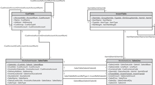
When generating a UML data model, the Reverse Engineering tool looks for tables in the project. The UML model contains a class for each table and view in the project and its attributes and associations. Figure 3-21 shows a class diagram with the CustTable (Customers), InventTable (Inventory Items), SalesTable (Sales Order Header), and SalesLine (Sales Order Line) tables. To simplify the diagram, some attributes have been removed.
The UML model also contains referenced tables and all extended data types, base enumerations, and X++ data types. You can include these items in your diagrams without having to run the Reverse Engineering tool again.
Fields in Dynamics AX are generated as UML attributes. All attributes are marked as public because of the nature of fields in Dynamics AX. Each attribute also shows the type. The primary key field is underlined. If a field is a part of one or more indexes, the names of the indexes are prefixed to the field name; if the index is unique, the index name is noted in brackets.
Relationships in Dynamics AX are generated as UML associations. The aggregation property of the association is set based on two conditions in metadata:
If the relationship is validating (the validate property is set to Yes), the aggregation property is set to shared. This is also known as UML aggregation, visualized by a white diamond.
If a cascading delete action exists between the two tables, a composite association is added to the model. A cascading delete action ties the life span of two or more tables and is visualized by a black diamond.
The end name on associations is the name of the Dynamics AX relationship, and the names and types of all fields in the relationship appear in brackets.
When generating an object model, the Reverse Engineering tool looks for Dynamics AX classes, tables, and interfaces in the project. The UML model contains a class for each Dynamics AX table and class in the project and an interface for each Dynamics AX interface. The UML model also contains attributes and operations, including return types, parameters, and the types of the parameters. Figure 3-22 shows an object model of the most important RunBase and Batch classes and interfaces in Dynamics AX. To simplify the view, some attributes and operations have been removed, and operation parameters are suppressed.

The UML model also contains referenced tables, classes and tables, and all extended data types, base enumerations, and X++ data types. You can include these elements in your diagrams without having to run the Reverse Engineering tool again.
Fields and member variables in Dynamics AX are generated as UML attributes. All fields are generated as public attributes, whereas member variables are generated as protected attributes. Each attribute also shows the type. Methods are generated as UML operations, including return type, parameters, and the types of the parameters.
The Reverse Engineering tool also picks up any generalizations (classes extending other classes), realizations (classes implementing interfaces), and associations (classes using each other). The associations are limited to references in member variables.
When generating an entity relationship data model, the Reverse Engineering tool looks for tables and views in the project. The entity relationship model contains an entity type for each AOT table in the project and attributes for each table’s fields. Figure 3-23 shows an Entity Relationship Diagram (ERD) with the CustTable (Customers), InventTable (Inventory Items), SalesTable (Sales Order Header), and SalesLine (Sales Order Line) tables. To simplify the diagram, some attributes have been removed.

Fields in Dynamics AX are generated as entity relationship columns. Columns can be foreign key (FK), alternate key (AK), inversion entry (IE), and optional (O). A foreign key column is used to identify a record in another table, an alternate key uniquely identifies a record in the current table, an inversion entry identifies zero or more records in the current table (these are typical of the fields in nonunique indexes), and optional columns don’t require a value.
Relationships in Dynamics AX are generated as entity relationships. The EntityRelationshipRole property of the relationship in Dynamics AX is used as the foreign key role name of the relation in the entity relationship data model.
Note
The Reverse Engineering tool produces an ERX file. To work with the generated file in Visio, you must start Visio, create a new Database Model Diagram and select Database, and point to Import and then Import Erwin ERX file. Afterward you can drag relevant tables from the Tables And Views pane (available from the Database menu) to the diagram canvas.
This small, helpful tool can be used in numerous scenarios. The Table Browser tool lets you see the records in a table without requiring you to build any user interface. This tool is useful when you’re debugging, validating data models, and modifying or cleaning up data, to name just a few uses.
You can access the Table Browser tool from the Add-Ins submenu in the AOT on:
Tables
Tables listed as data sources in forms, reports, Web forms, and Web reports
System tables listed in the AOT under System DocumentationTables
Note
The Table Browser tool is implemented in X++. You can find it in the AOT under the name SysTableBrowser. It is a good example of how to bind the data source to a table at run time.
Figure 3-24 shows the Table Browser tool started from the CustTable table. In addition to the querying, sorting, and filtering capabilities provided by the grid control, the Table Browser tool allows you to type an SQL SELECT statement directly into the form using X++ SELECT statement syntax and see a visual display of the result set. This tool is a great way to try out complex SELECT statements. It fully supports grouping, sorting, aggregation, and field lists.

The Table Browser tool also allows you to choose to see only the fields from the auto-report field group. These fields are printed in a report when the user clicks Print in a form with this table as a data source. Typically, these fields hold the most interesting information. This option can make it easier to find the values you’re looking for in tables with many fields.
Search is everything! The size of Dynamics AX applications calls for a powerful and effective search tool.
Tip
You can use the Find tool to search for an example of how to use an API. Real examples can complement the examples found in the documentation.
You can start the Find tool, shown in Figure 3-25, from any node in the AOT by pressing Ctrl+F or by clicking Find on the context menu. The Find tool supports multiple selections in the AOT.

The Name & Location tab defines what you’re searching for and where to look:
In Search, the menu options are Methods and All Nodes. When you choose All Nodes, the Properties tab appears.
The Named text box limits the search to nodes with the name you specify.
The Containing Text box specifies the text to look for in the method expressed as a regular expression.
When you select the Show Source Code check box, results include a snippet of source code containing the match, making it easier to browse the results.
By default, the Find tool searches the node (and its subnodes) selected in the AOT. If you change focus in the AOT while the Find tool is open, the Look In value is updated. This is quite useful if you want to search several nodes using the same criterion. You can disable this behavior by clearing the Use Selection check box.
In the Date tab, you specify additional ranges for your search, such as Modified Date and Modified By.
On the Advanced tab, you can specify more-advanced settings for your search, such as the layer to search, the size range of elements, the type of element, and the tier on which the element is set to run.
The Filter tab, shown in Figure 3-26, allows you to write a more complex query by using X++ and type libraries. The code written in the Source text box is the body of a method with the following profile.

The example in Figure 3-26 uses the class SysScannerClass to find any occurrence of the TTSAbort X++ keyword. The scanner is primarily used to pass tokens into the parser during compilation. Here, however, it detects the use of a particular keyword. This tool is more accurate (though slower) than using a regular expression, because X++ comments don’t produce tokens.
The Properties tab appears when All Nodes is selected in the Search menu. You can specify a search range for any property. Leaving the range blank for a property is a powerful setting when you want to inspect properties: it matches all nodes, and the property value is added as a column in the results, as shown in Figure 3-27. The search begins when you click Find Now. The results appear at the bottom of the dialog box as they are found.

Double-clicking any line in the result set opens the X++ code editor with focus on the matched code example. When you right-click the lines in the result set, a context menu containing the Add-Ins menu opens.
Several versions of the same element typically exist. These versions might emanate from various layers or revisions in version control, or they could be modified versions that exist in memory. Dynamics AX has a built-in Compare tool that highlights any differences between two versions of an element.
The comparison shows changes to elements, which can be modified in three ways:
A metadata property can be changed.
X++ code can be changed.
The order of subnodes can be changed, such as the order of tabs on a form.
You open the Compare tool by right-clicking an element and then clicking Compare on the Add-Ins submenu. A dialog box allows you to select the versions of the element you want to compare, as shown in Figure 3-28.

The versions to choose from come from many sources. The following is a list of all possible types of versions:
Standard layered version types. These include sys, syp, gls, glp, hfx, sl1, sl2, sl3, bus, bup, var, vap, cus, cup, usr, usp.
Old layered version types (old sys, old syp, and so on). If .aod files are present in the Old Application folder (located in Program FilesMicrosoft Dynamics AX50 ApplicationApplStandardOld), elements from the files are available here. This allows you to compare an older version of an element with its latest version. See Chapter 1 for more information on layers. In Chapter 1, Figure 1-3 illustrates the components in the application model layering system.
Version control revisions (Version 1, Version 2, and so on). You can retrieve any revision of an element from the version control system individually and use it for comparison. The version control system is explained later in this chapter.
Best practice washed version (Washed). A few simple best practice issues can be resolved automatically by a best practice "wash." Selecting the washed version shows you how your implementation differs from best practices. To get the full benefit of this, select the Case Sensitive check box on the Advanced tab.
Export/Import file (XPO). Before you import elements, you can compare them with existing elements (which they overwrite during import). You can use the Compare tool during the import process (CommandImport) by selecting the Show Details check box in the Import dialog box and right-clicking any elements that appear in bold. Objects in bold already exist in the application; objects not in bold do not.
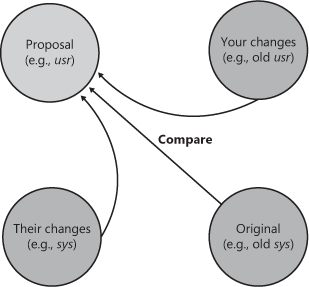
Upgraded version (Upgraded). MorphX can automatically create a proposal for how a class should be upgraded. The requirement for upgrading a class arises during a version upgrade. The Create Upgrade Project step in the Upgrade Checklist automatically detects customized classes that conflict with new versions of the class. A class is conflicting when you’ve changed the original version of the class, and the publisher of the class has also changed the original version. MorphX constructs the proposal by merging your changes and the publisher’s changes to the class. MorphX requires access to all three versions of the class—the original version in the Old Application folder, a version with your changes in the current layer in the Old Application folder, and a version with the publisher’s changes in the same layer as the original. The installation program ensures that the right versions are available in the right places during an upgrade. The conflict resolution is shown in Figure 3-29.
Note
You can also compare two different elements. To do this, select two elements in the AOT, right-click, point to Add-Ins, and then click Compare.
Figure 3-30 shows the Advanced tab, on which you can specify comparison options.

The comparison options shown in Figure 3-30 are described in the following list:
Show Differences Only. All equal nodes are suppressed from the view, making it easier to find the changed nodes. This option is selected by default.
Suppress Whitespace. White space, such as spaces and tabs, is suppressed into a single space when comparing. The Compare tool can ignore the amount of white space, just as the compiler does. This option is selected by default.
Case Sensitive. Because X++ is not case-sensitive, the Compare tool is also not case-sensitive by default. In certain scenarios, case sensitivity is required and must be enabled, such as when you’re using the best practice wash feature mentioned earlier in this section. The Case Sensitive option is not selected by default.
Show Line Numbers. The Compare tool can add line numbers to all displayed X++ code. This option is not selected by default but can be useful during an upgrade of large chunks of code.
After you choose elements and set parameters, you can start the comparison by clicking Compare. Results are displayed in a three-pane dialog box, as shown in Figure 3-31. The top pane is the element selection, the left pane is a tree structure resembling the AOT, and the right pane shows details of the tree selection.

The icons in the tree structure indicate how each node has changed. A red or blue check mark indicates that the node exists only in a red or blue element. Red corresponds to the sys layer, and blue corresponds to the old sys layer. A gray check mark indicates that the nodes are identical but one or more subnodes are different. A not-equal-to symbol (≠) on a red and blue background indicates that the nodes are different in the two versions.
Note
Each node in the tree view has a context menu that provides access to the Add-Ins submenu and the Open New Window option. The Open New Window option provides an AOT view on any element, including old layer elements.
Details of the differences are shown in the right pane. Color coding is also used in this pane to highlight differences. If an element is editable, small action icons appear. These icons allow you to make changes to source, metadata, and nodes, which can save you time when performing an upgrade. A right or left arrow removes or adds the difference, and a bent arrow moves the difference to another position. These arrows always come in pairs, so you can see where the difference is moved to and from. An element is editable if it is from the current layer and checked out if a version control system is used.
Although Dynamics AX uses the comparison functionality for development purposes only, the general comparison functionality can be used more widely. The available APIs allow you to compare and present differences in the tree structure or text representation of any type of entity.
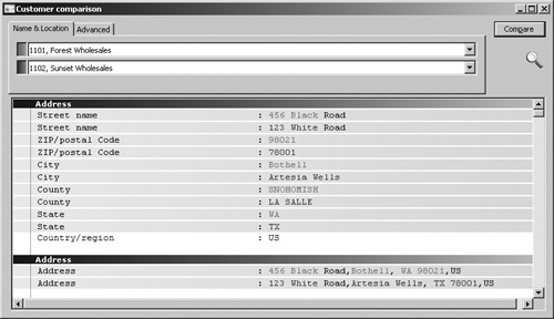
The Tutorial_CompareContextProvider class shows how simple it is to compare business data by using these APIs and presents it by using the Compare tool. The tutorial consists of two parts:
Tutorial_Comparable. This class implements the SysComparable interface. Basically, it creates a text representation of a customer.
Tutorial_CompareContextProvider. This class implements the SysCompareContext-Provider interface. It provides the context for comparison. For example, it lists a tutorial_ Comparable class for each customer, sets the default comparison options, and handles context menus.
Figure 3-32 shows a comparison of two customers, the result of running the tutorial.
You can also use the line-by-line comparison functionality directly in X++. The static run method on the SysCompareText class, shown in the following code, takes two strings as parameters and returns a container that highlights differences in the two strings. You can also use a set of optional parameters to control the comparison.
Refer to the Microsoft Dynamics AX 2009 SDK for documentation of the classes.
The concept of cross-references in Dynamics AX is simple. If an element uses another element, the reference is recorded. Cross-references allow you to determine which elements a particular element uses as well as which elements other elements are using. Dynamics AX provides the Cross-reference tool to access and manage cross-reference information.
You must update the Cross-reference tool regularly to ensure accuracy. The update typically takes several hours. The footprint in your database is about 1 gigabyte for the standard application.
You can update the Cross-reference tool by going to the Microsoft Dynamics AX drop-down menu and then pointing to ToolsDevelopment ToolsCross-referencePeriodicUpdate. Updating the Cross-reference tool also compiles the entire AOT because the compiler emits cross-reference information.
Tip
Keeping the Cross-reference tool up to date is important if you want to rely on its information. If you work in a shared development environment, you share cross-reference information with your team members. Updating the Cross-reference tool nightly is a good approach for a shared environment. If you work in a local development environment, you can keep the Cross-reference tool up to date by enabling cross-referencing when compiling. This option does slow down the compilation, however. Another option is to manually update cross-references for the elements in a project. You can do so by right-clicking the project, pointing to Add-Ins, pointing to Cross-reference, and then clicking Update.
In addition to the main cross-reference information, two smaller cross-reference subsystems exist:
Data model. This cross-reference subsystem stores information about relationships between tables. It is primarily used by the query form and the Reverse Engineering tool.
Type hierarchy. This cross-reference subsystem stores information about class and data type inheritance. It is used only in the Application Hierarchy Tree. The Application Hierarchy Tree is available from the Microsoft Dynamics AX drop-down menu, at Tools Development ToolsApplication Hierarchy Tree.
Further discussion of these tools is beyond the scope of this book. Refer to the Microsoft Dynamics AX 2009 SDK for more information on these subsystems and the tools that rely on them.
The cross-reference information the Cross-reference tool collects is quite complete. The following list shows the kinds of elements it cross-references. (Cross-reference information for elements followed by an asterisk is new in Dynamics AX 2009.) You can find the following list of cross-referenced elements and their values by opening the AOT, expanding the System Documentation node, and clicking Enums and then xRefKind.
BasicType
Class
ClassInstanceMethod
ClassStaticMethod
ClrType
ClrTypeMethod
ConfigurationKey
Dataset*
Enum
Enumerator
ExtendedType
Form*
Job*
Label
LicenseCode
Map
MapField
MapInstanceMethod
MapStaticMethod
Menu*
MenuItemAction
MenuItemDisplay
MenuItemOutput
Predefined (system functions)
Query*
Report*
SecurityKey
Table
TableField
TableIndex
TableInstanceMethod
TableStaticMethod
WebActionItem
WebDisplayContentItem
WebForm*
WebManagedContentItem*
WebMenu*
WebModule*
WebOutputContentItem
WebReport*
WebUrlItem
When the Cross-reference tool is updated, it scans all metadata and X++ code for references to elements of the kinds listed here.
Tip
It’s a good idea to use intrinsic functions when referring to elements in X++ code. An intrinsic function can evaluate to either an element name or an ID. The intrinsic functions are named <ElementKind>Str or <ElementKind>Num, respectively. Using intrinsic functions provides two benefits: you have compile-time verification that the element you reference actually exists, and the reference is picked up by the Cross-reference tool. Also, there is no run-time overhead. An example follows.
// Prints ID of MyClass, such as 50001 print classNum(myClass); // Prints "MyClass" print classStr(myClass); // No compile check or cross-reference print "MyClass"; |
See Chapter 15, for more information about intrinsic functions.
The primary function of the Cross-reference tool is to determine where a particular element is being used. Here are a couple of scenarios:
You want to find usage examples. If the product documentation doesn’t help, you can use the Cross-reference tool to find real implementation examples.
You need to perform an impact analysis. If you’re changing an element, you need to know which other elements are affected by your change.
To access usage information, right-click any element in the AOT, point to Add-Ins, point to Cross-reference, and then click Used By. If the option isn’t available, either the element isn’t used or that cross-reference hasn’t been updated.
Figure 3-33 shows where the prompt method is used on the RunBaseBatch class.

When you view cross-references for a class method, the Application Hierarchy Tree is visible, allowing you to see whether the same method is used on a parent or subclass. For types that don’t support inheritance, such as tables, table methods, and table fields, the Application Hierarchy Tree is hidden.
The Version Control tool is a feature in MorphX that makes it possible to use a version control system, such as Microsoft Visual SourceSafe or Microsoft Visual Studio Team Foundation Server, to keep track of changes to elements in the AOT. The tool is accessible from several places: from the Microsoft Dynamics AX drop-down menu at ToolsDevelopment Tools Version Control, from toolbars in the AOT and X++ code editor, and from the context menu on elements in the AOT.
Using a version control system offers several benefits:
Revision history of all elements. All changes are captured along with a description of the change, making it possible to consult change history and retrieve old versions of an element.
Code quality enforcement. The implementation of version control in Dynamics AX enables a fully configurable quality bar for all check-ins. With the quality bar, all changes are verified according to coding practices. If the change doesn’t meet the criteria, it is rejected. Microsoft uses the quality bar for all check-ins, which has helped raise the quality of X++ code to an unprecedented level. Microsoft developers cannot check in code with compiler errors, compile warnings, or best practice errors. In the final stages of development, tasks in code (to-dos) are also prohibited.
Isolated development. Each developer can have a local installation and make all modifications locally. When modifications are ready, they can be checked in and made available to consumers of the build. So a developer can rewrite fundamental areas of the system without causing any instability issues for others. Developers are also unaffected by any downtime of a centralized development server.
Even though using a version control system when developing is optional, we strongly recommend you consider one for any development project. Dynamics AX 2009 supports three version control systems: Visual SourceSafe 6.0 and Team Foundation Server, which are designed for large development projects, and MorphX VCS. MorphX VCS is designed for smaller development projects that previously couldn’t justify the additional overhead that using a version control system server adds to the entire process. Table 3-7 shows a side-by-side comparison of the version control system options.
Table 3-7. Overview of Version Control Systems
Classic MorphX (No Version Control) | MorphX VCS | Visual SourceSafe | Team Foundation Server | |
|---|---|---|---|---|
Application Object Servers required | 1 | 1 | 1 per developer | 1 per developer |
Database servers required | 1 | 1 | 1 per developer | 1 per developer |
Team server required | No | Optional | Yes | Yes |
Build process required | No | No | Yes | Yes |
Master file | AOD | AOD | XPOs | XPOs |
Isolated development | No | No | Yes | Yes |
Multiple check-out | N/A | No | Configurable | Configurable |
Change description | No | Yes | Yes | Yes |
Change history | No | Yes | Yes | Yes |
Change list support (atomic check-in of a set of files) | N/A | No | No | Yes |
Code quality enforcement | No | Configurable | Configurable | Configurable |
The elements persisted in the version control server are file representations of the elements in the AOT. The file format used is the standard Dynamics AX export format (.xpo). Each .xpo file contains only one element.
There are no additional infrastructure requirements when you use MorphX VCS, which makes it a perfect fit for partners running many parallel projects. In such setups, each developer often works simultaneously on several projects, toggling between projects and returning to past projects. In these situations, the benefits of having change history are enormous. With just a few clicks, you can enable MorphX VCS to persist the changes in the business database. Although MorphX VCS provides many of the same capabilities as a version control server, it does have some limitations. For example, MorphX VCS does not provide any tools for maintenance, such as backup, archiving, or labeling.
In contrast, Visual SourceSafe and Team Foundation Server are designed for large projects in which many developers work together on the same project for an extended period of time (e.g., an independent software vendor building a vertical solution).
Figure 3-34 shows a typical deployment using Visual SourceSafe or Team Foundation Server, in which each developer locally hosts the AOS and the database. Each developer also needs a copy of all .xpo files. When a developer communicates with the version control server, the .xpo files are transmitted. A unique ID is required when the developer creates a new element or label. A Team Server, available as a Microsoft .NET Web service, is required to ensure uniqueness of IDs across all the local developers’ environments. The Team Server is a component available with Dynamics AX.
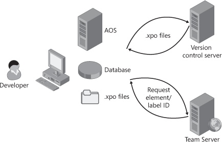
Figure 3-35 shows the element life cycle in a version control system. When the element is in a state marked with green, it can be edited; otherwise it is read-only.
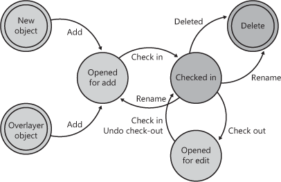
You can create a new element in two ways:
After you create an element, you must add it to the version control system. First give it a proper name in accordance with naming conventions, and then click Add To Version Control on the context menu. After you create the element, you must check it in.
An element that is checked in can be renamed. Renaming an element deletes the element with the old name and adds an element with the new name.
To modify an element, you must check it out. Checking out an element locks it so that others can’t modify it while you’re working.
By clicking ToolsDevelopment ToolsVersion ControlPending Objects from the Microsoft Dynamics AX drop-down menu, you can see which elements you currently have checked out. The elements you’ve checked out (or that you’ve created and not yet checked in), appear in blue, rather than black, in the AOT.
If you decide that you don’t want to modify an element that you checked out, you can undo the check-out. This releases your lock on the element and imports the server version of the element to undo your changes.
When you have finalized your modifications, you must check in the elements for them to be part of the next build. When you click Check-In on the context menu, the dialog box shown in Figure 3-36 appears, displaying all the elements that you currently have checked out. The Check In dialog box shows all open elements by default; you can remove any elements not required in the check-in from the list by pressing Alt+F9.

We recommend the following procedure for checking in your work:
Before the version control system accepts a check-in, it might subject the elements to quality checks. You define what is accepted in a check-in when you set up the version control system. The following checks are supported:
Compiler errors
Compiler warnings
Compiler tasks
Best practice errors
When a check is enabled, it is carried out when you do a check-in. If the check fails, the check-in stops. You must address the issue and restart the check-in.
You can set the Source Code Titlecase Update tool, available on the Add-Ins submenu, to automatically execute before elements are checked in to ensure uniform casing in variable and parameter declarations and references. You can specify this parameter when setting up the version control system by selecting the Run Title Case Update check box.
When using version control, you create new elements just as you normally would in the MorphX environment without a version control system. These elements are not part of your check-in until you click Add To Version Control on the context menu.
You can also create all element types except those listed in System Settings (from the Microsoft Dynamics AX drop-down menu: ToolsDevelopment ToolsVersion ControlSetup System Settings). By default, jobs and private projects are not accepted.
New elements should follow Dynamics AX naming conventions. The best practice naming conventions are enforced by default, so you can’t check in elements with names such as aaaElement, Del_Element, element1, or element2. (The only Del elements allowed are those required for version upgrade purposes.) You can change naming requirements in System Settings.
An element must be in the checked-in state to be renamed. Because all references in .xpo files are strictly name based (not ID based), all references to renamed elements must be updated. For example, when you rename a table field, you must also update any form or report that uses that field. Most references in metadata in the AOT are ID based, thus not affected when an element is renamed; in most cases, it is enough to simply check out the form or report and include it in the check-in to update the .xpo file. You can leverage the cross-reference functionality to identify references. References in X++ code are name based. You can use the compiler to find affected references.
An element’s revision history is kept intact when elements are renamed. No tracking information in the version control system is lost because of a rename.
You delete an element as you normally would in Dynamics AX. The delete operation must be checked in before the deletion is visible to other users of the version control system. You can see pending deletions in the Pending Objects dialog box.
Working with labels is very similar to working with elements. To change, delete, or add a label, you must check out the label file containing the label. You can check out the label file from the Label Editor dialog box.
The main difference between checking out elements and checking out label files is that simultaneous check-outs are allowed for label files. This means that others can change labels while you have a label file checked out.
When you check in a label file, your changes are automatically merged into the latest version of the file. If you modify or delete a label that another person has also modified or deleted, your changes are lost. Lost changes are shown in the Infolog.
The ID server guarantees that label IDs are unique; adding labels won’t generate conflicts.
If someone else has checked in a new version of an element, the Get Latest option on the context menu allows you to get the version of the element that was most recently checked in. This option isn’t available when you have the element checked out yourself.
Get Latest is not applicable to MorphX VCS.
Synchronization allows you to get the latest version of all elements. This step is required before you can check in any elements. You can initiate synchronization from the Microsoft Dynamics AX drop-down menu: ToolsDevelopment ToolsVersion ControlPeriodicSynchronize.
Synchronization is divided into three operations that happen automatically in the following sequence:
Copy the latest files from the version control server to the local disk.
Import the files into the AOT.
Compile the imported files.
You should use synchronization to make sure your system is up to date. Synchronization won’t affect any new elements that you have created or any elements that you have checked out.
Figure 3-37 shows the Synchronization dialog box.

Selecting the Force check box gets the latest version of all files, whether or not they have changed, and then imports every file.
When using Visual SourceSafe, you can also synchronize to a label defined in Visual SourceSafe. This way you can easily synchronize to a specific build or version number.
Synchronization is not applicable to MorphX VCS.
How you keep track of versions on the client depends on the version control system being used. Visual SourceSafe requires that Dynamics AX keep track of itself. When you synchronize the latest version, it is copied to the local repository folder from the version control system. Each file must be imported into Dynamics AX to be reflected in the AOT. To minimize the risk of partial synchronization, a log entry is created for each file. When all files are copied locally, the log is processed, and the files are automatically imported into Dynamics AX.
When synchronization fails, the import operation is usually the cause of any problems. Synchronization failure leaves your system in a partially synchronized state. To complete the synchronization, you must restart Dynamics AX and restart the import. You use the synchronization log to restart the import, and you access it from the Microsoft Dynamics AX dropdown menu at ToolsDevelopment ToolsVersion ControlInquiriesSynchronization Log.
The Synchronization Log dialog box, shown in Figure 3-38, displays each batch of files, and you can restart the import by clicking Process. If the Processed check box is not selected, the import has failed and should be restarted.

The Synchronization Log is not available in MorphX VCS.
One of the biggest advantages of version control is the ability to track changes to elements. Selecting History on an element’s context menu displays a list of all changes to an element, as shown in Figure 3-39.

This dialog box shows the version number, the action performed, the time the action was performed, and who performed the action. You can also see the change number and the change description.
A set of buttons in the revision history dialog box allows further investigation of each version. Clicking Contents opens a form that shows other elements included in the same change. Clicking Compare opens the Compare dialog box, which allows you to do a line-by-line comparison of two versions of the element. The Open New Window button opens an AOT window that shows the selected version of the element, which is useful for investigating properties because it allows you to use the standard MorphX toolbox. Clicking View File opens the .xpo file for the selected version in Notepad.
Comparison is the key to harvesting the benefits of a version control system. You can start a comparison from several places, including the Compare option on the Add-Ins submenu. Figure 3-40 shows the Comparison dialog box where two revisions of the form CustTable are selected.

The Compare dialog box contains a list of all checked-in versions, in addition to the layer element versions, when a version control system is used.
When you’re working on a project, it’s easy to lose track of which elements you’ve opened for editing. The Pending Objects dialog box, shown in Figure 3-41, lists the elements that are currently checked out in the version control system. Notice the column containing the action performed on the element. Deleted elements are available only in this dialog box; they are no longer shown in the AOT.
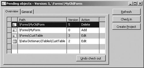
You can access the Pending Objects dialog box from the Microsoft Dynamics AX drop-down menu: ToolsDevelopment ToolsVersion ControlPending Objects.
Because the version control system contains .xpo files, and not an .aod file, a build process is required to generate an .aod file from the .xpo files. The following procedure is a high-level overview of the build process.
Use the CombineXPOs command-line utility to create one .xpo file by combining all .xpo files. The purpose of this step is to make the .xpo file consumable by Dynamics AX. Dynamics AX requires all referenced elements to be present in the .xpo file or to already exist in the AOT to maintain the references during import.
Import the new .xpo file by using the command-line parameter -AOTIMPORTFILE=<FileName.xpo> to Ax32.exe. This step imports the .xpo file and compiles everything. After it is complete, the new .aod file is ready.
You must follow these steps for each layer you build. The steps are described in more detail in the Microsoft Dynamics AX 2009 SDK.
The build process doesn’t apply to MorphX VCS.
The implementation of the version control system in Dynamics AX is fully pluggable. This means that any version control system can be integrated with Dynamics AX.
Integrating with another version control system requires a new class implementing the SysVersionControlFileBasedBackEnd interface. It is the implementation’s responsibility to provide the communication with the version control system server being used.
A unit test is a piece of code that exercises another piece of code and ascertains that it behaves correctly. The developer who implements the unit to be tested typically writes the unit test. Thought leaders in this area recommend writing unit tests as early as possible, even before writing a single line of the unit’s code. This principle is called test-driven development. (You can read more about test-driven development on MSDN and more about unit testing in the Unit Test Framework section of the Microsoft Dynamics AX 2009 SDK.)
Writing unit tests early forces you to consider how your code will be consumed; this in turn makes your APIs easier to use and understand, and it results in constructs that are more likely to be robust and long lasting. With this technique, you must have at least one unit test for each requirement; a failing unit test indicates an unfulfilled requirement. Development efforts should be targeted at making the failing unit test succeed—no more, no less.
To reap the full benefits of unit testing, you should execute test cases regularly, preferably each time code is changed. The Unit Test framework in Dynamics AX supports you regardless of your approach to writing unit tests. For example, the unit test capabilities are fully embedded in MorphX, and you can easily toggle between writing test cases and writing business logic.
If you’re managing an implementation project for Dynamics AX, you should advocate testing and support your team members in any way required. At first glance, unit testing might seem like more work, but the investment is well worth the effort. If you’re a team member on a project that doesn’t do unit testing, you should convince your manager of its benefits. Plenty of recent literature describes the benefits in great detail.
When implementing unit tests, you write a test class, also referred to as a test case. Each test case has several test methods that exercise the object being tested in a particular way. As you build your library of test cases, you’ll find that you need to organize them into groups. You can group test cases into test suites. The simplest way to do this is to use test projects, which are simply special kinds of AOT projects.
To implement a unit test case, you must create a new class that extends the SysTestCase class, which is part of the Unit Test framework. You should give the class the same name as the class it is testing, suffixed with Test. This is illustrated in the following example, where a unit test for the Stack class is declared.
If you were to run the unit test at this point, you would find that zero tests were run and zero tests failed.
This default naming convention tells the Unit Test framework which test class to collect code coverage data for. If the default test class name doesn’t suit your needs, you can override the testsElementName method. You can also override the testsElementType method to set the kind of element for which the framework collects code coverage data.
To create a useful test, you must add one or more test methods to the class. All test method names must start with test. The test methods must return void and take no parameters. In the following code, a test method is added to the StackTest class.
Within each test method, you should exercise the object you test and confirm that it behaves correctly. Running the unit test at this point tells you that one test was run and zero tests failed.
Your testing needs should be met by the assertion methods available on SysTestCase (which extends SysTestAssert), as shown in Table 3-8.
Table 3-8. Assertion Methods on the SysTestCase Class
Method | Parameters | Action |
|---|---|---|
assertEquals | (anyType, anyType) | Asserts that two values are equal. When the argument is of type object, the equal method is called to compare them. |
assertFalse | (boolean) | Asserts that the value is false. |
assertNotEqual | (anyType, anyType) | Asserts that two values are different. |
assertNotNull | (object) | Asserts that the value is not null. |
assertNotSame | (object, object) | Asserts that the objects referenced are not the same. |
assertNull | (object) | Asserts that the value is null. |
assertRealEquals | (real, real [, real delta]) | Asserts that real values differ no more than the delta. |
assertSame | (object, object) | Asserts that the objects referenced are the same. |
assertTrue | (boolean) | Asserts that the value is true. |
If an assertion fails, the test method fails. You can configure the framework to stop at first failure or continue with the next test method in the Unit Test Parameters dialog box: from the Microsoft Dynamics AX drop-down menu, point to Tools Development ToolsUnit Test Parameters. The following code adds a new failing test method.
Running the unit test at this point shows that two tests were executed and one failed. The failing test appears in the Infolog. Clicking Edit opens the X++ code editor on the assert call that failed.
You might have noticed code redundancy in the test methods shown so far. In many cases, initialization code is required before the test method can run. Instead of duplicating this code in all test methods, you can refactor it into the setUp method. If teardown logic is required, you can place it in the tearDown method. When the framework runs a test method, it instantiates a new test case class, which is followed by calls to setUp and test methods, and finally a call to the tearDown method. This prevents in-memory data from one test method from affecting another test method. Test suites, which are covered in the next section, provide ways to isolate data persisted in the database between test cases and methods. The following code uses the setUp method to refactor the sample code.
The Unit Test framework also supports testing of exceptions. If a method is expected to throw an exception, you can instruct the framework to expect an exception to be thrown. If you expect an exception and none is thrown, the framework reports the test case as failed. You inform the framework that an exception is expected by calling parmExceptionExpected ([boolean, str]). You can specify an exception text that must exactly match the text thrown with the exception, or the test case will fail. You shouldn’t write more asserts after the method call expected to throw an exception because execution should never get that far. The following code adds a test method that expects an exception message to be thrown.
void testFailingPop()
{;
    //Assert that an exception is expected.
    this.parmExceptionExpected(true, "Stack is empty!");

    //Call the method expected to throw an exception.
    stack.pop();
} |
The sample test case now has three test methods. By following these steps, you can run the test case from MorphX:
If you wanted to run the test case programmatically, you could use a test runner class. To do this, you would typically place the following logic in your test class’s main method, which is invoked when you press F5 in the X++ code editor.
Notice that you also register a listener. If you didn’t register a listener, you wouldn’t know the result of the test. Listeners are described in the section "Test Listeners" later in this chapter.
Test suites serve two purposes:
Collection of test cases and test suites. A test suite can contain any number of test cases and other test suites. This arrangement means that you can group test cases in a hierarchy.
Test case isolation. Each test case could have different needs for isolation, depending on what data it changes. In fact, each method within the test case could have a need for isolation.
Dynamics AX includes the following five test suites that provide different levels of isolation:
SysTestSuite. This test suite is the default. It provides no isolation. You can override the setUp and tearDown methods, if necessary. Note that these methods are not the same as the setUp and tearDown methods on the test case.
SysTestSuiteCompanyIsolateClass. This test suite constructs an empty company account for the entire test class and runs each test method in the company account. After all test methods have been executed, the company account is deleted.
SysTestSuiteCompanyIsolateMethod. This test suite constructs an empty company account for each test method and runs the test method in the company account. After the test methods have been executed, the company account is deleted. This test suite provides the highest isolation level. It does, however, have a noticeable effect on performance.
SysTestSuiteTTS. This test suite wraps each test method in a transaction. After the test method has been completed, the transaction is aborted. This provides a fast alternative to the company isolation suites, but it has a couple of limitations:
Exceptions can’t be handled. Exceptions thrown inside a transaction abort the transaction automatically and can’t be caught inside the transaction.
Test cases that require data to be committed can’t use this test suite.
SysTestSuiteCompIsolateClassWithTts. This test suite provides a combination of SysTestSuiteCompanyIsolateClass and SysTestSuiteTTS.
For each test case, you can override the createSuite method to select the appropriate suite for your test case. The following code shows how to use the company isolation test suite in the StackTest class.
We recommend that you use test projects to group your test cases into suites. You can, however, create your own class extending from SysTestSuite and programmatically add test cases and other test suites to it. You can run each test suite in one of the following ways:
The following code shows the entire StackTest test case. Notice the refactoring and the changes in testQty to make the test case succeed.
The easiest way to group test cases is to use a test project. You can create a test project with the Project Designer in MorphX. The test project can contain groups of test case classes and references to other test projects. You create a new test project by selecting the project type Test Project when creating either a shared or private project. A test project can also contain references to other test projects, which allows the project to scale across many development teams. You create a reference by right-clicking the project root node and selecting New Reference To Test Project.
Figure 3-42 shows a test project that includes a group of common tests containing the test case example and references to two other test projects.

Each test project has its own settings that are persisted with the project definition. This allows you to specify test project settings that follow the project, even through import and export, redeployment, and so on.
You can run a test project in several ways:
Right-click it, and then click Run.
Type the name in the Test toolbar, and then click Run.
Start the Dynamics AX client with the following command line:
StartupCmd=RunTestProject_<Name of test project>
Use the version control functionality during check-in. Check-in stops if the test fails. You specify the project to run during check-in: from the Microsoft Dynamics AX drop-down menu, point to ToolsDevelopment ToolsVersion ControlSetupSystem Settings.
When you’re working with unit testing, you should open the Test toolbar. You access the Test toolbar, shown in Figure 3-43, from the Microsoft Dynamics AX drop-down menu: Tools Development ToolsUnit TestShow Toolbar.
You can type the name of the test case, test suite, or test project you want to run, click Run to execute it, and then, to get information about the result, click Details to open the Test Jobs window. The Test Jobs window shows you the following information collected during the test execution:
The status of each test case
Environmental information
Timing (when the test started and stopped, the duration of the test, and so on)
Code coverage, when enabled
Information sent to the Infolog during the test case execution
The Unit Test framework can collect code coverage information during execution, including a percentage value that indicates how thoroughly you have tested the unit. It also allows you to focus your implementation of the test cases on the parts not covered by other test cases. In addition, the Test Jobs window offers a line-by-line view of the code lines visited. You can enable code coverage in the Unit Test Parameters dialog box: from the Microsoft Dynamics AX drop-down menu, point to ToolsDevelopment ToolsUnit TestParameters. However, because much more data is collected, enabling code coverage when executing unit tests dramatically affects performance during execution. Figure 3-44 shows an example of the code coverage recorded by the testFailingPop method from the preceding test case example.

The lines highlighted in gray (lines 1 through 5 and 15 through 16) are the lines visited during execution. The lines not shaded (lines 6 through 14) haven’t been visited.
The value of running a test case is dramatically increased if good reporting options exist. When running a test case or a suite of tests, you can enable one or more listeners. Each listener produces its unique output. Dynamics AX includes many listeners, allowing output to text files, XML files, the database, the Infolog, the Message window, the Print window, and the Progress bar. You can enable test listeners in the Unit Test Parameters dialog box.
Here is the XML generated by the XML listener when you run the StackTest unit test.
Note
Listeners that generate a file write the file to the application log directory. The only way to change the file name and location is to manually register a listener, which we demonstrated in the StackTest code in Test Suites to Test Projects.
If you must create a new listener to output to a type of media not supported by default, you can do so by following these steps:
Create your own listener class implementing the SysTestListener interface. Alternatively, you can inherit from one of the existing test listeners. The methods on your class are invoked when events such as the start and end of test suites and test cases occur and when test cases fail. A SysTestListenerData object is passed to each method. The object contains information about the test case or suite, coverage data, and much more. By extracting the information, you can generate output to suit your needs.
Modify the base enumeration SysTestListeners. You must add an entry that has the same name as your listener class and a label of your choice. This causes the listener to appear in the test parameters form.
So far in this chapter we’ve described the classes in the Unit Test framework and explained how they interact. Figure 3-45 shows this information as a UML object model.

The SysTestCase class implements quite a few interfaces. In fact, the Unit Test framework can use any class that implements the SysTestable interface as a test case. You can implement the other interfaces if you want more control. It’s far easier, however, to create test case classes that extend the SysTestCase base class. (For simplicity, Figure 3-45 doesn’t show the SysTestSuite derived classes or the SysTestListener derived classes.)