In this chapter: |
The objectives of this chapter are to:
Introduce MorphX, the Microsoft Dynamics AX 2009 integrated development environment (IDE).
Show how the MorphX IDE is used throughout a typical product cycle model.
Describe the application model elements and their relationships.
Dynamics AX has two development environments: Microsoft Visual Studio, used primarily for developing Enterprise Portal and reports, and MorphX, the main Dynamics AX IDE and the focus of this chapter. For more information about Enterprise Portal, see Chapter 7, and for more on reports, see Chapter 11.
MorphX is a model-based, object-oriented development environment. Developers use X++—the MorphX programming language—and the MorphX toolset to develop, customize, and extend Microsoft Dynamics AX applications. You can find more information about X++ in Chapter 4.
This chapter provides an overview of the MorphX IDE. First, in the context of a product cycle model, we introduce the MorphX tools you use when building a Microsoft Dynamics AX application. The tools are described in more detail in Chapter 3. Then we cover the key elements in the application model of the Application Object Tree (AOT).
Like most IDEs, MorphX includes, among other tools, a source code editor, a compiler, a version control system, and a debugger.
In this section, you’ll see how these tools map to a typical product cycle model, shown in Figure 2-1. Again, refer to Chapter 3 for more in-depth information about the MorphX tools.

You can follow the model shown in Figure 2-1 strictly, use variations, or manage your projects less formally. Whatever style of project management you choose for running your projects, you need to consider what should happen in each of these five phases: planning, designing, implementing, stabilizing, and releasing.
Most software projects start with a planning phase. In this phase, product planners decide on the market segment, establish the vision for the product, and allocate resources.
In the design phase, design documents are created, design reviews are conducted, prototypes are implemented, and requirements are documented. In the next phase, implementation, code is written, tested, and shipped. When implementation is complete, the stabilization phase begins. Here the focus is to validate the product quality: Are all requirements met? Does the product work as intended? Does the product meet performance goals?
When the product stability is satisfactory, the product can be released. The release phase includes packaging, marketing, and maintenance, which might involve releasing error corrections and service packs.
The product cycle starts over with the next version of the product.
Note
It is beyond the scope of this book to discuss how to run software projects optimally. For more information about how to best manage software projects, see Steve McConnell’s book Rapid Development (Microsoft Press, 1996).
Unlike many development environments, in the Dynamics AX IDE, you never start from scratch. Even in your first Dynamics AX project, when you might have a lot of learning to do, practices to formulate, and partnerships to form, you have a code base to start with.
In the planning phase of a Dynamics AX project, application designers and developers investigate the existing functionality and plan how to integrate with this functionality at a high level. Typically, this takes place at the user interface level.
Best Practices
It’s a good idea to do this kind of investigation in demo mode. Dynamics AX automatically enters demo mode when you skip the License Information step in the Installation checklist. The main benefit of investigating in demo mode is that all product functionality is available; if a license file is loaded, only the functionality purchased for that particular license is available. When all functionality is available, you can more effectively plan how to integrate with existing functionality—and avoid implementing redundant functionality.
Keep in mind that when you work in demo mode, the number of users, allowed active instances of Application Object Server (AOS), and companies is limited. In demo mode, the MorphX IDE isn’t available, the date-handling algorithm is limited, and dates after a certain threshold date can’t be used.
As we said earlier, in the design phase of the product cycle, prototypes are implemented, design documents are created, design reviews are conducted, and requirements are documented.
As you develop your designs and prototypes, the first Dynamics AX tool you’re likely to use is the Application Object Tree (AOT). Accessible through the Dynamics AX user interface by pressing Ctrl+D or by clicking the toolbar icon, the AOT is typically the starting place for all development in Dynamics AX. It is the repository for all the elements that together constitute the existing business application.
The next tools you encounter are the property sheet and the X++ code editor. Most nodes in the AOT have a set of properties that you can inspect and modify by using the property sheet. Method nodes contain X++ source code. You use the X++ code editor to view and modify the code.
With these tools, you can, for example, see the structure of forms (by using the AOT), the properties specified on each control (by using the property sheet), and the event handlers’ implementation (by using the X++ code editor). You use these tools throughout the remaining phases of the product cycle.
If you use the Version Control tool, you benefit from all elements being read-only. In read-only mode, you can investigate without the risk of changing the existing code. If you’re working on the first version of your project, you can also use the layering technology to provide the same safeguard.
The tools mentioned so far reveal implementation details at the element level. Three additional tools show how elements relate to each other at a higher level: the Cross-reference tool, the Find tool, and the Reverse Engineering tool.
The Cross-reference tool shows you where any specific element is used. In the design phase, you can use this tool to determine where table fields are displayed, initialized, read, modified, and so on. The Find tool allows you to search any element in the AOT. In the design phase, you typically search the entire AOT. The Reverse Engineering tool raises the abstraction level. With this tool, you can generate Microsoft Visio Unified Modeling Language (UML) models and Entity Relationship Diagrams (ERDs). If you find yourself struggling to understand the object hierarchies or the data models, looking at a UML diagram can be useful.
During the design phase, you should also consider your approach to testing. Designing for testing from the beginning makes your life easier later in the product cycle, and it typically results in a better design. See Chapter 3 for information on implementing unit tests by using MorphX.
When your design documents and functional specifications are complete and you’re ready to start developing, you should consider setting up the Version Control tool. Version control allows you to keep track of all changes, which is particularly useful when you are working in large teams. You can also specify criteria for code quality. Code that doesn’t conform to the code quality you specify is rejected in the version control check-in process, so you can be sure that code that doesn’t meet the quality standard isn’t allowed into your project.
In your first implementation, you should use the Development Project to group related elements. Without it, working efficiently in the AOT can be difficult because of the many elements it contains. A project provides a view into the AOT, allowing you to focus on the elements you’re working with. Using a development project also allows you to define what you want to see and the structure in which you see it.
After you’ve written your source code with the X++ code editor, you must compile it. The compiler generates the bytecode from your X++ source code and presents any syntax errors. The compiler also triggers the Best Practices tool, which validates your implementation of X++ code and element definitions according to development guidelines, allowing you to automatically detect coding errors and warnings.
You can also use the Visual Form Designer and the Visual Report Designer to construct your forms and reports. If you’re developing a multilingual feature, you can use the Label Editor to create localizable text resources.
You might want to refer to code examples during the implementation phase. The Find tool and the Cross-reference tool can help you identify examples for API usage. The Cross-reference tool is also helpful if you need to refactor your code.
If your code doesn’t produce the results you expect or it has errors, you can use the Dynamics AX Debugger to track the problem. The debugger starts automatically when execution hits a breakpoint. You might also need to see the data that your feature is using. You can use the Table Browser tool to look at this data.
When you’ve completed your implementation, you should find and correct any problems in your code—without introducing new problems. You can use the debugger to find problems in your code. If a problem mandates a change of method profiles (return values or parameters), you should use the Cross-reference tool to perform an impact analysis of your changes before you make them. If you use the Version Control tool to track changes, you can use the Compare tool to highlight differences in each revision of an element.
When upgrading your customers from one version of an application to the next, say, from an earlier version of Dynamics AX or from one version of your functionality to the next, you need to ensure that no code conflicts exist. To detect any conflicting changes to elements, you can use the Detect Code Upgrade Conflicts option, which is available from the Upgrade checklist or the Microsoft Dynamics AX drop-down menu in the client: ToolsDevelopment ToolsCode Upgrade. To resolve conflicts, the Compare tool is unmatched. It allows you to compare versions of elements, and, based on the results, upgrade elements. See Chapter 18, for more information about finding and resolving conflicts.
You build an application with MorphX using modeling. The building blocks available for modeling are commonly known as application model elements. In this section, we introduce the different kinds of application model elements and their relationships, describe the tools necessary for working with application model elements, and explain the sequence in which to apply the tools. For a more thorough explanation of the application model elements, refer to the Microsoft Dynamics AX SDK on MSDN.
The application model dictionary in the AOT organizes the application model elements. For example, rich client forms are grouped under Forms, rich client reports are grouped under Reports, and Web client forms and reports are collected under a Reported Libraries group.
Tip
To better understand the application model element structure as you read, start Dynamics AX 2009 and open the AOT.
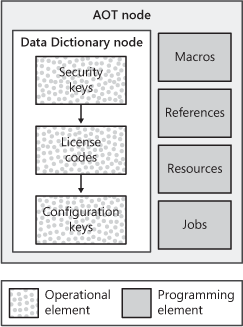
Operational model elements are used to model how the application should behave according to security, configuration, and licensing in an operational environment. For example, certain functionality is available only if it is enabled system-wide and the user is authorized to use it. Programming model elements provide ways to reference library code, definitions, and resources. They also allow you to write small X++ scripts to experiment with the X++ language capabilities.
Here are the operational model elements:
License codes
Configuration keys
Security keys
These model elements change the operational characteristics of the Dynamics AX development and runtime environments.
These are the types of programming model elements:
Reference elements. Elements whose properties identify the Microsoft .NET assemblies referenced in X++ statements
Resource elements. Named file resources loaded into the memory
Macro elements. Libraries of X++ string replacement procedures
Job elements. X++ programs primarily used for testing and debugging an executable from within the development environment
Figure 2-2 illustrates the operational and programming element categories in the AOT.
You use the AOT and the property sheet to declaratively group related application features by associating configuration keys with menu item elements and data elements. This enables the application administrator to enable and disable application features. The MorphX IDE synchronizes table and view elements with the database schema only if they are associated with an active configuration key or if they have no configuration key. For details, see the section "Database Model Elements" later in this chapter and the section "Database Synchronization" in Chapter 14. The Dynamics AX runtime environment renders presentation controls only for menu items that are associated with an active configuration key or that have no configuration key. You can enable and disable application logic by using X++ to test for the state of a configuration key.
Dynamics AX includes all the application modules developed by Microsoft. These modules are locked with license codes that must be unlocked with license keys. You can also configure an unlocked module by using configuration keys. Dynamics AX administrators manually enable and disable configuration keys by using the check boxes in the system configuration dialog box at AdministrationSetupSystemConfiguration. You can manually activate configuration keys associated with license code elements only if there is a valid license key for the corresponding license code element.
Security keys are part of the Dynamics AX security framework. When a user identified by a Windows principal logs on to a Dynamics AX application, he or she is authenticated with the Windows platform security infrastructure and then associated with a Dynamics AX application user group that denotes the application user’s role. An application user role determines which user interface actions a user is authorized to perform and which data the user is authorized to view and modify.
Security keys are associated with menu item elements and data elements so that related elements can be grouped together into a security group. Access permissions that are assigned to a security key apply to all elements that are members of the associated security group. Access permissions can also be assigned to individual elements in a security group. The security grouping provided by security keys is used to display a tree of security keys and application elements when they are displayed in the User Group Permissions dialog box. This makes it easier for the application administrator to navigate the thousands of menu item elements and data elements that need to be assigned user group permissions.
The following list describes the programming model elements:
Reference elements. Reference elements hold references to .NET assemblies for the .NET common language runtime (CLR) types to be incorporated natively into X++ source code. The X++ editor reads type data from the referenced assemblies so that IntelliSense is available for CLR namespaces, types, and type members. The MorphX compiler uses the CLR type definitions in the referenced assembly for type and member syntax validation, and the Dynamics AX runtime uses the reference elements to locate and load the referenced assembly.
Resource elements. Resource elements hold references to file resources that are read from the file system and stored in memory. Image and animation files used when developing Web client applications are referenced as resources. The name of the file that contains the resource also references the resource when it is stored in the database.
Macro elements. Macro elements are libraries of X++ syntax replacement procedures included in the X++ source code. You should use macro libraries to provide readable names for constants. See Chapter 4 for an example of a macro procedure and an example that shows how to include a macro library in X++ source code.
Job elements. Job elements are X++ source code statements that are easily executed by selecting the CommandGo menu item or by pressing F5 on the keyboard while using MorphX. Job elements offer a convenient method of experimenting with features of the X++ language when they are used to write sample code. See Chapter 4 for an example of X++ code statements written in a job model element. You shouldn’t use job elements for writing application code. In fact, the Dynamics AX enterprise resource planning (ERP) application model contains no job element when it is released to customers and development partners.
Figure 2-3 illustrates the value type, database, and data association element categories that are located in the Data Dictionary node in the AOT. Configuration key elements can be associated with base enumeration and extended data type elements as well as with table, view, and map elements. Table, view, and map application elements can also be associated with security key elements.

A base enumeration element (sometimes shortened to enum) defines a name for a group of symbolic constants that are used in X++ code statements. For example, an enumeration with the name WeekDay can be defined to name the group of symbolic constants that includes Monday, Tuesday, Wednesday, Thursday, Friday, Saturday, and Sunday.
An extended data type element can extend a base enumeration by providing a new name for a group of symbolic constants that includes the base enumeration elements. An extended data type element can also extend the string, boolean, int, real, date, time, UtcDateTime, int64, guid, and container types. An extended data type definition can also comprise a set of application parameters that define how the Dynamics AX runtime renders user interface controls. For example, an extended data type representing an account number extends a string value type, restricts its length to 10 characters, and sets its user interface label to "Account number."
Extended data types also support inheritance. For example, an extended data type that defines an account number can be specialized by other extended data types defining customer and vendor account numbers. The specialized extended data type inherits properties, such as string length, label, and help text. You can override some of the properties on the specialized extended data type. You constrain the possible values of an extended data type and define a database table association by adding a relationship from the extended data type to a table field element. The Dynamics AX runtime automatically ensures that the values of the extended data type are consistent with this relationship. The runtime also uses the defined relationship to navigate between rich client and Web client main table forms when a user selects the Go To The Main Table Form menu item. This menu item appears when a user right-clicks a form data grid column that is mapped to a table element field whose type is an extended data type with a defined relationship.
Database model elements are database table and view definitions that correspond to database server entities and relationships as well as query elements that define database query statements. The MorphX IDE synchronizes table and view element definitions with database schema definitions. This feature allows Dynamics AX to use either Microsoft SQL Server or Oracle database server as an application database. MorphX synchronizes only those database elements that have configuration keys enabled and corresponding valid license keys.
Database element keys and indexes are used to create database entity keys and indexes, but data element interrelationships are not used to create integrity relationships in a database. Instead, they validate data entries to automatically join and select database data as a user navigates between forms, and they join data sources associated with a form. For example, a user sees confirmations only for the selected sales orders when navigating from a sales order form to a sales order confirmation form. Moreover, MorphX automatically converts between X++ programming value types such as string, enum, and boolean and their corresponding database data types, such as nvarchar and int. For example, an X++ string defined to have a maximum length of 10 characters is stored as a database nvarchar data type defined to have a maximum length of 10 characters.
A table element can also define table field groups, menu item references, table relationships, delete actions, and methods that are used by the Dynamics AX runtime when it renders data entry presentation controls and ensures the referential integrity of the database. The X++ editor also uses these elements to support developers with IntelliSense when they write X++ statements that create, read, update, and delete data in the database. You can also use the AOT to associate table elements with data source elements on forms, reports, queries, and views.
View elements define database table view entities and are synchronized with the application database. View elements can include a query that filters data in a table or data joined from multiple tables. View element definitions also include table field mappings and methods. Views are read-only and primarily provide an efficient method for reading data. View elements can be associated with form and report data sources and are instantiated in X++ variable declarations.
Query elements define a database query structure that can be executed from X++ statements, particularly X++ statements used in classes that derive from the RunBase class. You add tables to query element data sources and specify how they should be joined. You also specify how data is returned from the query, such as by using sort order and range specifications.
Map elements don’t define database entities, so they’re not synchronized with the database. They actually define X++ programming elements that wrap table objects at run time. Map elements associate common fields and methods for tables that are not in third-normal form. For example, the CustTable and VendTable table elements in the Dynamics AX application model are mapped to the AddressMap map element so that developers can use one AddressMap object to access common address fields and methods. The MorphX compiler validates that table variables assigned to map variables are defined as valid element mappings.
Note
Maps provide a useful common interface to data entities and prevent the need to duplicate methods on denormalized tables, but you should use maps only when normalization isn’t an option.
Table collection elements define groups of tables that can be shared by two or more Dynamics AX companies that share virtual company accounts. The application administrator creates a virtual company and then adds table collections to it. The administrator also adds the virtual company accounts to an actual Dynamics AX company’s accounts. The Dynamics AX runtime uses the virtual company data area identifier instead of the actual company data area identifier when it inserts or reads data in the tables in the table collection.
Caution
The tables placed in a table collection shouldn’t have foreign key relationships with tables outside the table collection unless specific extensions are written to maintain the relational integrity of the database.
Perspective elements define views on the Dynamics AX database model by grouping related tables. Perspectives are used to design and generate ad hoc reports in Microsoft SQL Server Reporting Services.
Class elements define the structure and behavior of business logic types that work on ERP reference data and business transaction data. These elements comprise object-oriented type definitions that instantiate business objects at run time. You define type declaration headers and methods by using the X++ programming language. You associate rich client and Web client menu item elements in the AOT with class element methods by using the property sheet in MorphX. This allows the Dynamics AX runtime to instantiate corresponding business logic objects when users select action, display, or output menu item controls on a user interface.
The Dynamics AX runtime also invokes business object methods when they overload event handlers on tables, forms, and reports. Class elements are also defined for application integration scenarios that aren’t driven by a user interface. Chapter 17, describes how these elements are associated with XML document elements that read from and write to the file system, Microsoft Message Queuing (MSMQ), and Web services.
The two types of presentation elements include rich client model elements and Web client model elements. The rich client element categories, Forms and Reports, are located under the AOT root node, and the Web client element categories, Web Forms and Web Reports, are under the Web node. Presentation elements are form, report, menu, or menu item definitions for either a Windows client application, called a rich client application, or a Windows SharePoint Services client application, called a Web client application. Both types of clients have a control layout feature called IntelliMorph. IntelliMorph automatically lays out presentation controls based on model element property and security settings. Presentation controls are automatically supplied with database and calculated data when their data source elements are associated with database or temporary table fields.
Figure 2-4 illustrates the rich client elements and their relationships. Configuration key and security key elements can be associated with menu and menu item elements. This association prevents users from executing application code that doesn’t have a license key or an active configuration key.

Table elements can also be associated with menu item elements. Each table element definition includes an optional display menu item element reference that, by convention, launches a form presentation control that renders the data from the database table in a grid control. The Dynamics AX runtime also automatically adds a Go To The Main Table Form menu item to a drop-down menu that appears when a user right-clicks a grid cell whose associated table column has a foreign key relationship with another table. The Dynamics AX runtime uses the referenced table’s menu item element to launch the form that renders the data from the foreign key table.
Menu elements define logical menu item groupings. Menu definitions can include submenu elements and other menu elements. The menu element named MainMenu defines the menu entries for the Dynamics AX navigation pane. As a new feature in Dynamics AX 2009, menus can also work as a hyperlink. This is modeled by specifying a menu item.
Menu item elements define hyperlinks labeled for display, action, and output that the Dynamics AX runtime uses to instantiate and execute reports, Reporting Services reports, business logic objects (defined by using class elements), and forms. When rendering forms and reports, the Dynamics AX runtime ignores menu items that are disabled by configuration keys, security keys, or role-based access permissions.
Form elements define a presentation control with which users insert, update, and read database data. A form definition includes a data source and a design element that defines the controls that must be rendered on the form as well as their data source mappings. A form is launched when a user clicks a display menu item control, such as a button. Data sources on a form can be table, view, or query elements.
Report elements define a presentation control that renders database and calculated data in a page layout format. A report can be sent to the screen, a printer, a printer archive, an e-mail account, or the file system. A report definition includes a data source and a design element that define the output-only controls that must be rendered on the report as well as their data source mappings. A report is launched when a user clicks an output menu item control, such as a button.
Report libraries are a logical grouping of Reporting Services reports, data sources, style templates, layout templates, and images. Each report library represents a single Dynamics AX Reports Library project. You can edit an existing report library or create a new one using Microsoft Visual Studio 2008 if you have the Dynamics AX Reporting Tools component installed. Reporting Services reports that are part of a report library in the AOT can be associated with menu items. For more information on reporting with Dynamics AX, see Chapter 11.
Workflow elements define workflow documents and event handlers by using class elements. Workflow elements define the workflow tasks, such as approve and reject, by associating the tasks with menu items. When a form is workflow enabled, it automatically renders controls supporting the user in performing the tasks in the workflow.
Figure 2-5 illustrates the Web client model elements used to define Enterprise Portal. You can associate configuration key and security key elements with Web menu items and Web content elements to ensure that code without license keys are an active configuration key that can’t be executed.

Web menu elements define logical Web menu item groupings. Web menu definitions can include submenu application elements and other Web menu application elements. Web menu items are rendered as hyperlinks on Web pages.
Web menu item elements define hyperlinks containing URLs and class labels that the Dynamics AX runtime environment uses to navigate between Web pages and to generate Web pages, respectively. Web module elements define the site structure. The Web modules are created as subsites under one parent home site in Windows SharePoint Services.
Web file elements define file references to components required by Windows SharePoint Services. These components include site definitions, templates, and Web part installation files. The MorphX IDE saves these files to a specified Web server at deployment time.
Data set elements define the data sources used by the Web user controls. They offer a rich programming model in the AOT for defining data access, validation, calculation, and so on. The data set elements also expose business data to Web user controls through standard ASP.NET data binding via the AxDataSource control.
Web control elements store the Web user control’s markup and code-behind files. You can create Web user controls in Visual Studio 2008 and add them directly to the AOT by using the Dynamics AX Visual Studio add-in. Web user controls define the user interface for interacting with business data.
Data sets, Web controls, and report libraries are the elements used by the newly architected, ASP.NET-based Enterprise Portal framework. (The Enterprise Portal framework has been rewritten for Dynamics AX 2009. For more information on Enterprise Portal, see Chapter 7.) These elements replace the X++-based Enterprise Portal framework (supported in deprecated mode in Dynamics AX 2009), which uses Weblet, Web form, and Web report elements.
Weblet elements define references to class application elements that extend the Weblet class definition. Weblet objects return HTML documents whose format is governed by input parameters.
Web form elements define Web presentation controls with which users insert, update, and read database data. A Web form definition includes a data source and a design element that defines the controls that must be rendered on the Web form, as well as their data source mappings. A Web form is generated when a Web page hosting the Web form is generated.
Web report elements define Web presentation controls that render database and calculated data in a Web format. A report definition includes a data source and a design element that define the output-only controls that must be rendered on the report, as well as their data source mappings. A Web report is generated when a Web page hosting the Web form is generated.
Web content elements define managed, display, and output elements that reference Web user control, Web form, Web report, and (rich) report elements for their content.
Web page elements define the composition of an HTML document element that comprises Web content elements and Web menu elements.