
7
Coordinated Dynamic Stability and Voltage Regulation
Power systems continuously experience changes in operating conditions due to variations in generation/load and a wide range of disturbances. Power system stability and voltage regulation have been considered as important control problems for secure system operation over the years. Currently, because of expanding physical setups, functionality, and complexity of power systems, the proper design of automatic voltage regulators (AVRs) and power system stabilizers (PSSs) has becomes more significant than in the past. That is why in recent years a great deal of attention has been paid to the application of advanced control techniques for power systems.
Conventionally, the AVR and PSS design is considered as a sequential design including two separate stages without any coordination. Although it is known that the stability and voltage regulation issues are ascribed to different model descriptions, it has been long recognized that the AVR and PSS have inherent conflicting objectives.
In the present chapter, the necessity for coordination of AVR and PSS designs is emphasized, and three synthesis methodologies to enhance the stability and voltage regulation of existing real power systems without opening their conventional PSS and AVR loops are introduced.
7.1 Need for AVR–PSS Coordination
As mentioned, the AVR and PSS are conventionally designed as two separate stages in the classical sequential synthesis procedure. First, the AVR is designed to meet the specified voltage regulation performance and then the PSS is designed to satisfy the stability and required damping performance. The conventional PSS and AVR structures are described in Chapter 5.
An AVR keeps the generator terminal voltage at a preset value, and improves transient stability. However, the fast responding AVRs deteriorate small signal stability by introducing electromechanical modes in the power system [1]. Continuous load/generation changes and various disturbances impose low frequency oscillations in a power system [2]. When an electromechanical oscillation occurs, the torque resolved into two components, one in phase with machine rotor angle (synchronizing torque) and the other in phase with machine rotor speed (damping torque). The lack of synchronizing and/or damping torque may lead to system instability. Before the widespread use of AVRs, instability has mainly occurred due to lack of synchronizing torque. This type of instability was manifested in the form of aperiodic drift of the rotor angle of the synchronous machines. The installed AVRs improve synchronizing torque in the power system. Other types of instability are the result of the lack of damping torque as sustained or increased oscillations of rotor angles [3]. Therefore, the AVRs improve transient stability due to the increase in the synchronizing torque between interconnected generators, and the decrease in small-signal stability and damping torque due to the increase of rotor oscillations. A conventional AVR and excitation control system is shown in Fig. 7.1a.

Figure 7.1 (a) Conventional AVR and excitation control system. (b) Conventional PSS.
The PSSs are used to attenuate the low-frequency oscillations. The PSSs are employed to produce an auxiliary damping torque and enhance the stability margin. A PSS usually includes two phase-lead compensators (to compensate existing phase-lag between exciter input and electrical torque), a reset/washout filter (to eliminate DC signals), and a constant gain as shown in Fig. 7.1b. The AVR and PSS units are usually connected together as shown in Fig. 5.2.
Rotors of generating units such as steam generator turbines are made of several connected pieces through the shaft with different masses. Although in power system dynamic analysis, the steam generator–turbine rotor is usually considered as a single mass unit; however, a disturbance may practically create torsional oscillations between the pieces as well as low-frequency oscillations. This problem to be magnified concerning the existing installed PSSs [4]. Usually to remove torsional oscillation, torsional filters are required to provide appropriate input speed/frequency signals for the PSSs.
The AVRs and PSSs produce torques in phase with the rotor angle and speed variations, respectively. However, both AVR and PSS employ field voltage to produce different rotor angle and speed-based torques, but an enhancement in one direction may cause deterioration in the other direction. Therefore, due to this conflict, a tradeoff between AVR and PSS control actions is required. The impact of AVR and PSS on the power system stability is shown in Fig. 7.2.
Figure 7.2 Impact of AVR and PSS on the power system stability: (a) constant excitation, (b) constant excitation and AVR, and (c) constant excitation with AVR and PSS.
In this figure, the torques resolved into damping and synchronizing components. The system is stable when these components have positive values. In Fig. 7.2a, the impact of constant excitation without PSS and AVR on the power system is depicted. It clarifies that the system is operating in a stable condition. Adding AVR injects an extra torque with positive synchronizing and large negative damping component to the system, which result in total negative damping torque (Fig. 7.2b). The lack of damping torque component in this condition makes the system unstable (oscillatory instability). Applying a torque in phase with the rotor speed variation (using PSS) compensates the lack of damping torque and conduct the system to a stable condition (Fig. 7.2c).
Numerous oscillation modes exist in a large-scale power system, wherein removing all of them is neither practical nor economical. However, there are two important modes, namely, local and interarea modes that should be controlled by the PSSs. The local mode appears in the frequency range of 0.8–2.0 Hz and occur when generators in a plant swing against the rest of the power system. As described in Chapters 2 and 6, the interarea mode (in the range of 0.1–0.7 Hz) occurs when two groups of generators in different areas swing against each other.
The main issue in using of AVR and PSS is how to tune their parameters. In general, the PSS philosophy relies on phase compensation using linear control theory. The PSS parameters are tuned to provide a desirable performance at the nominal operating point. Most of the previous works considered the conventional AVR and PSS structures with two separate design stages. First, the AVR parameters are tuned to achieve acceptable transient stability, and then the PSS is designed to meet the required damping characteristic.
Although, it has been long recognized that AVR and PSS have inherent conflicting objectives, most of the previous works have addressed the AVR and PSS designs, neglecting the existing conflict. Furthermore, so many simplified assumptions in these reports degrade the performance of controllers in practice [1].
In the last two decades, several reports considering an integrated synthesis approach for the AVR and PSS designs and covering various requirements for stabilization and voltage regulation within unique control structure have been published. Although most of the addressed approaches have been proposed based on new contributions in modern control systems, because of complexity of the control structure, numerous unknown design parameters, neglecting real constraints, and probable risk of placement instead of well-known conventional AVR/PSS units, they are not well suited to meet the design objectives in real multimachine power systems.
In response to these problems, this chapter presents three tuning mechanisms to enhance the stability and voltage regulation of existing real power systems without removing conventional PSS and AVR units. The proposed coordination methodologies use measurable signals for robust tuning of control proportional gains; therefore, they have considerable promise for implementation, especially in a large-scale multimachine system. In fact, the proposed control strategies attempt to make a bridge between the simplicity of control structure and robustness of stability and performance to satisfy simultaneous AVR and PSS objectives.
7.2 A Survey on Recent Achievements
In the last few decades, some studies have considered an integrated design approach to the AVR and PSS design using domain partitioning, robust pole-replacement, and adaptive control [5–7]. Moreover, recently several control methods have been made to coordinate the various requirements for stabilization and voltage regulation within one new control structure [1,8–12].
The published papers on the AVR and PSS coordination concerning the applied methodologies can be classified into four categories. These four methodology groups are identification/prediction technique, switching concept, intelligent technique, and optimization/robust control approach.
The complexity of the identification process and the resulting model is an important problem of the first category. It will be more difficult for a large-scale power system with a high dimension and time-varying and nonlinearity properties. Here, the control strategies of the first category are briefly discussed and some of their advantages and disadvantages are demonstrated.
A robust control method, namely, the internal model control (IMC), was employed to construct a robust controller for coordinated power system voltage regulator and stabilizer synthesis in Refs [13,14]. The IMC theory states that control can be achieved only if the control system encapsulates some representation of the plant to be controlled. In this method, plant output is predicted by using the plant model. A high performance of IMC is achieved when the open-loop system is stable and the exact model is available. In practice, often the exact model is not available and the open-loop system is also unstable. Therefore, first the system should be stabilized by a feedback controller, and then the prestabilized system must be used for the application of the conventional IMC to obtain the final robust coordinator.
Using the model predictive control (MPC) method, a trade-off between the AVR and PSS performance requirements is provided in Ref. [15]. The method uses the two-axis model of the synchronous generator to perform control action signal. For this purpose, the current and voltage components are used to compute the field voltage, which is required to satisfy the voltage regulation and small signal stability [15]. The MPC method is initially suitable for systems with large time constants, while power system small-signal stability is a small timescale phenomenon. Moreover, time-variance and the high nonlinearity of power systems, as well as the complexity of the controller structure are the other problems of the mentioned control strategy.
The switching concept-based coordination method for transient stability and voltage regulation is addressed in Refs [9,16]. Using the trial and error method, for each specific fault, a unique switching time is obtained. In Ref. [16], direct feedback linearization (DFL) is used to design a robust controller to improve the voltage regulation and transient stability. In the proposed method, the line reactance and infinite bus voltage are assumed as constants. The DFL idea is to algebraically transform nonlinear system equations into the linear ones, so that linear control techniques can be applied. In this work, the postfault voltage and prefault line reactance are considered as uncertain parameters and then the DFL technique is applied to obtain a robust coordinator. The design problem is finally transformed to solve an algebraic Riccati equation (ARE).
The obtained DFL compensating control law through the solution of the ARE can be represented as follows:
where ![]() is the angle,
is the angle, ![]() is the frequency,
is the frequency, ![]() is the electrical power, and
is the electrical power, and ![]() is a linear function with respect to
is a linear function with respect to ![]() ,
, ![]() , and
, and ![]() . By differentiating terminal voltage equation in the linearized power system model, Equation (7.1) can be obtained in the term of
. By differentiating terminal voltage equation in the linearized power system model, Equation (7.1) can be obtained in the term of ![]() vector. Similarly, for the postfault condition, the voltage control law can be obtained as
vector. Similarly, for the postfault condition, the voltage control law can be obtained as
Following a fault, the control signal ![]() is employed to keep the generators in synchronism; then in the postfault, the feedback law switches to
is employed to keep the generators in synchronism; then in the postfault, the feedback law switches to ![]() , which is employed to enhance the power system performance [10,18]. Figure 7.3 shows the block diagram realization of this approach, schematically.
, which is employed to enhance the power system performance [10,18]. Figure 7.3 shows the block diagram realization of this approach, schematically.

Figure 7.3 Switching-based coordination method.
Several intelligent approaches, specifically fuzzy logic-based voltage regulation and oscillation damping coordinator designs are reported over the years. The methods introduced in Refs [10,11] belong to the third category. The nonrobustness drawback of the switching concept-based method is compensated by weighing the controller output according to the operating points. A global controller to improve transient stability and to achieve satisfactory postfault voltage level in the presence of disturbances is introduced in Ref. [10]. In this work, two trapezoid-shaped membership functions (![]() ,
, ![]() ) were used such that
) were used such that
where
In the transient period, ![]() becomes the dominant value, while in the postfault state
becomes the dominant value, while in the postfault state ![]() becomes the dominant value. According to the operating condition, the control laws are weighted to get a satisfactory performance by performing final coordinating control action signal
becomes the dominant value. According to the operating condition, the control laws are weighted to get a satisfactory performance by performing final coordinating control action signal ![]() :
:
where ![]() is the control signal of the DFL controller (7.1), and
is the control signal of the DFL controller (7.1), and ![]() is the control signal of voltage regulator (7.2). In fact, the membership functions determine the participation rate of each controller. A block diagram of the mentioned controller is shown in Fig. 7.4. As can be seen, in addition to the complexity of the overall control framework, an extra unit is required to generate the weights.
is the control signal of voltage regulator (7.2). In fact, the membership functions determine the participation rate of each controller. A block diagram of the mentioned controller is shown in Fig. 7.4. As can be seen, in addition to the complexity of the overall control framework, an extra unit is required to generate the weights.

Figure 7.4 Weighed switching-based coordination method.
In Ref. [19], the particle swarm optimization (PSO) technique is used to solve the simultaneous damping and synchronization problem through minimizing of a comprehensive damping index. Some features of the PSO such as less computation time and few memory requirements make it attractive for solving the present optimization problem. Using a linearized dynamic model without considering uncertainty and neglecting the exciter dynamic decreases the effectiveness of the mentioned methodology for real-world power systems. The application of optimal and robust control techniques for coordinating AVR and PSS are given in several papers [1,8,12,20].
Complexity of control structure, numerous unknown design parameters, as well as neglecting real constraints can be seen in most of the published coordination control techniques. In practice, usually controllers with a simple structure are preferable. On the other hand, the authors' experience shows that although conventional PSS and AVR systems may be incapable of obtaining desirable dynamic performances for a wide range of operating conditions, the electric power industry still is too conservative to open the conventional control loops and test the new/advanced coordination units, because of probable risks and bugs.
The mentioned challenge is addressed in Refs [1,12] by providing a simple gain vector feedback in parallel with the conventional AVR and PSS units. The design objectives are formulated via a robust static output feedback control problem, and the optimal static gains are obtained using an iterative linear matrix inequalities algorithm.
7.3 A Robust Simultaneous AVR–PSS Synthesis Approach
This section presents a methodology to enhance the stability and voltage regulation of existing real power systems without opening their conventional PSS and AVR units. The methodology provides a simple gain vector in parallel with the conventional control devices. The design objectives are formulated via an H∞ static output feedback (H∞-SOF) control problem and the optimal static gains are obtained using an iterative linear matrix inequalities (ILMI) algorithm. This work is fully presented in Ref. [1].
The proposed controller includes proportional gains and uses the measurable signals, so it has considerable promise for implementation, especially in a multimachine power system. In fact, the proposed control strategy attempts to make a bridge between simplicity in control structure and robustness in stability and performance to satisfy the AVR and PSS objectives, simultaneously.
To demonstrate the efficiency of the control methodology, some real-time nonlinear laboratory tests have been performed on a four-machine infinite bus system using the Analog Network Simulator (ANS) at the Research Laboratory of the Kyushu Electric Power Company (KEPCO) in Japan. The obtained results are compared with the conventional AVR–PSS design.
7.3.1 Control Framework
The overall control structure using the SOF control design for a given power system is shown in Fig. 7.5, where the PSS and AVR blocks represent the existing conventional power system stabilizer and voltage regulator. Here, the electrical power signal ![]() is considered as the input signal for the PSS unit. The static feedback controller (optimal gain vector) uses the terminal voltage
is considered as the input signal for the PSS unit. The static feedback controller (optimal gain vector) uses the terminal voltage ![]() , electrical power
, electrical power ![]() and machine speed
and machine speed ![]() as input signals. The
as input signals. The ![]() and
and ![]() show the reference voltage deviation and system disturbance inputs, respectively.
show the reference voltage deviation and system disturbance inputs, respectively.
Figure 7.5 Overall control structure.
Consider the linearized model of a given power system “i” in the following state-space form:
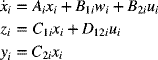
where ![]() is the state variable vector,
is the state variable vector, ![]() is the disturbance and area interface vector,
is the disturbance and area interface vector, ![]() is the control input vector,
is the control input vector, ![]() is the controlled output vector, and
is the controlled output vector, and ![]() is the measured output vector. The
is the measured output vector. The ![]() ,
, ![]() ,
, ![]() ,
, ![]() ,
, ![]() , and
, and ![]() are real matrices/vectors with appropriate dimensions.
are real matrices/vectors with appropriate dimensions.
Using standard H∞-SOF configuration [1] while considering appropriate controlled output signals results in an effective control framework, which is shown in Fig. 7.6. This control structure adapts the H∞-SOF control technique with the described power system control targets and allows direct trade-off between voltage regulation and closed-loop stability by mere tuning of a gain vector.

Figure 7.6 The proposed H∞-SOF control framework.
Here, disturbance input vector ![]() , controlled output vector
, controlled output vector ![]() , and measured output vector
, and measured output vector ![]() are considered as follows:
are considered as follows:
The ![]() and
and ![]() can be easily expressed in terms of system states, and the
can be easily expressed in terms of system states, and the ![]() ,
, ![]() , and
, and ![]() are constant weights that must be chosen by the designer to get the desired closed-loop performance. Since the vector
are constant weights that must be chosen by the designer to get the desired closed-loop performance. Since the vector ![]() properly covers all significant controlled signals that must be minimized by an ideal AVR–PSS design, it is expected that the proposed robust controller could be able to satisfy the voltage regulation and stabilizing objectives, simultaneously. Since the solution must be obtained through minimizing of the H∞ optimization problem, the designed feedback system should satisfy the robust stability and voltage regulation performance for the overall closed-loop system. Moreover, the developed ILMI algorithm (which is described in the next section) provides an effective and flexible tool to find an appropriate solution in the form of a simple static gain controller.
properly covers all significant controlled signals that must be minimized by an ideal AVR–PSS design, it is expected that the proposed robust controller could be able to satisfy the voltage regulation and stabilizing objectives, simultaneously. Since the solution must be obtained through minimizing of the H∞ optimization problem, the designed feedback system should satisfy the robust stability and voltage regulation performance for the overall closed-loop system. Moreover, the developed ILMI algorithm (which is described in the next section) provides an effective and flexible tool to find an appropriate solution in the form of a simple static gain controller.
7.3.2 Developed Algorithm
The formulation of static output feedback stabilization generally leads to a bilinear matrix inequalities (BMI) problem, which is a nonconvex problem. As described in Ref. [21], system (A, B, C) is stabilizable via the SOF if and only if there exist P > 0, X > 0 (symmetric and positive-definite matrices) and ![]() satisfying the following quadratic matrix inequality:
satisfying the following quadratic matrix inequality:
This kind of problem can be solved by an iterative algorithm that may not converge to an optimal solution. Here, in order to solve the H∞-SOF, an iterative LMI algorithm has been used. The key point is to formulate the H∞ problem via a generalized static output stabilization feedback such that all eigenvalues of (A−B ![]() C) shift toward the left half plane in the complex s-plane, to close to feasibility of (7.10). The general static output feedback control theory [1] gives a family of internally stabilizing SOF gain matrix defined as
C) shift toward the left half plane in the complex s-plane, to close to feasibility of (7.10). The general static output feedback control theory [1] gives a family of internally stabilizing SOF gain matrix defined as ![]() . Here, the desirable solution
. Here, the desirable solution ![]() is an admissible SOF law
is an admissible SOF law
such that
where ![]() is a small positive number. The performance index
is a small positive number. The performance index ![]() indicates a lower bound such that the closed-loop system is H∞ stabilizable. The optimal performance index (
indicates a lower bound such that the closed-loop system is H∞ stabilizable. The optimal performance index (![]() ), can be obtained from the application of a full dynamic H∞ dynamic output feedback control method. The proposed algorithm, which gives an ILMI solution for the mentioned optimization problem includes the following steps [1]:
), can be obtained from the application of a full dynamic H∞ dynamic output feedback control method. The proposed algorithm, which gives an ILMI solution for the mentioned optimization problem includes the following steps [1]:
- Step 1: Set initial values and compute the generalized system (
 ) and
) and  as given in (7.13), for the given power system including conventional AVR and PSS units.
For this purpose, the matrix
 has the following form, and the elements of other matrices in (7.13) can be obtained based on the structure of the used excitation system, AVR and PSS units:(7.14)
The “c” is used for the conventional AVR–PSS system,
 is obtained from the linearized state space model of targeted generator, which can be expressed as
  . A modeling method to obtain a fourth-order linear state-space model for a typical generator is explained in Appendix C.
 - Step 2: Set i = 1,
 and let
  .
.  and
and  are positive real numbers.
 - Step 3: Select
 , and solve
  from the following ARE:
(7.15)
from the following ARE:
(7.15)
Set
 .
. - Step 4: Solve the following optimization problem for
 ,
,  , and
, and  .
.
Minimize
 subject to the LMI constraints
Denote
 as the minimized value of
  .
. - Step 5: If
 , go to step 8.
 - Step 6: For
 , if
, if  ,
,  is an H∞ controller and
  indicates a lower bound such that the system is H∞ stabilizable via SOF control. Go to step 10.
 - Step 7: If
 , solve the following optimization problem for
  and
and  :
:
Minimize trace (
 ) subject to the LMI constraints (7.16–7.17) with
  . Denote
  as the
  that minimized trace (
 ). Go to step 9.
 - Step 8: Set
 , i = i + 1. Then do steps 3–5.
 - Step 9: Set i = i + 1 and
 , then go to step 4.
 - Step 10: If the obtained solution (
 ) satisfies the gain constraint, it is desirable; otherwise, retune constant weights (
 ) and go to step 1.


The vector ![]() is a constant weight vector that must be chosen by the designer to get the desired closed-loop performance. The selection of these weights depends on the specified voltage regulation and damping performance objectives. In fact an important issue with regard to the selection of the weights is the degree to which they can guarantee the satisfaction of design performance objectives. It is notable that
is a constant weight vector that must be chosen by the designer to get the desired closed-loop performance. The selection of these weights depends on the specified voltage regulation and damping performance objectives. In fact an important issue with regard to the selection of the weights is the degree to which they can guarantee the satisfaction of design performance objectives. It is notable that ![]() sets a limit on the allowed control signal to penalize fast changes, large overshoot with a reasonable control gain to meet the feasibility and corresponding physical constraints. Therefore, the selection of constant weights entails a compromise among several performance requirements.
sets a limit on the allowed control signal to penalize fast changes, large overshoot with a reasonable control gain to meet the feasibility and corresponding physical constraints. Therefore, the selection of constant weights entails a compromise among several performance requirements.
One can simply fix the weights to unity and use the method with regional pole placement technique for performance tuning. Here, for the sake of weight selection, the following steps are simply considered through the proposed ILMI algorithm:
- Step 1: Set initial values for
 , for example, [1 1 1].
 - Step 2: Run the ILMI algorithm.
- Step 3: If the ILMI algorithm gives a feasible solution such that it satisfies the robust H∞ performance and gain constraints, the assigned weights vector is acceptable. Otherwise, retune
 and go to step 2.
The proposed iterative LMI algorithm shows that if we simply perturb ![]() to
to ![]() for some
for some ![]() , then we will find a solution of the matrix inequality (7.16) for the performed generalized plant. That is, there exist a real number (
, then we will find a solution of the matrix inequality (7.16) for the performed generalized plant. That is, there exist a real number (![]() ) and a matrix P > 0 to satisfy inequality (7.16). Consequently, the closed-loop system matrix
) and a matrix P > 0 to satisfy inequality (7.16). Consequently, the closed-loop system matrix ![]() has eigenvalues on the left-hand side of the line
has eigenvalues on the left-hand side of the line ![]() in the complex s-plane. Based on the idea that all eigenvalues of
in the complex s-plane. Based on the idea that all eigenvalues of ![]() are shifted progressively toward the left half plane through the reduction of
are shifted progressively toward the left half plane through the reduction of ![]() . The given generalized eigenvalue minimization in the proposed iterative LMI algorithm guarantees this progressive reduction.
. The given generalized eigenvalue minimization in the proposed iterative LMI algorithm guarantees this progressive reduction.
7.3.3 Real-Time Implementation
To illustrate the effectiveness of the proposed control strategy, a real-time experiment was performed at the ANS laboratory. For the purpose of this study, a longitudinal four-machine infinite bus system is considered as the test system. A single line representation of the study system is shown in Fig. 7.7. Although in the given model the number of generators is reduced to four, it closely represents the dynamic behavior of the West Japan Power System [1]. The most important global and local oscillation modes of the actual system are included. For the study system, the local and global low-frequency oscillation modes are around 1.5 and 0.3 Hz, respectively. Each unit is a thermal unit and has its own conventional excitation control system as shown in Fig. 7.1a (for units 2 and 3) and Fig. 7.8 (for units 1 and 4).

Figure 7.7 Four-machine infinite bus power system.
Figure 7.8 Excitation control system for units 1 and 4.
Each unit has a full set of governor–turbine system (governor, steam valve servo-system, high-pressure turbine, intermediate-pressure turbine, and low-pressure turbine), which is shown in Fig. 7.9. The generators, lines, conventional excitation system, and governor–turbine parameters are given in Table C.1 to Table C.5 in Appendix C.

Figure 7.9 Speed governing and turbine system.
Unit 1 is selected to be equipped with a robust controller, and therefore our objective is to apply the control strategy described in the previous section to the controller design for unit 1. The whole power system has been implemented in the ANS laboratory. Figure 7.10 shows the overview of the applied laboratory experiment devices including the control/monitoring desks. A digital oscilloscope and a notebook computer are used for monitoring purposes.
Figure 7.10 Performed laboratory experiment: control/monitoring desks.
The proposed control loop (Fig. 7.11) has been built in a personal computer connected to the power system using a digital signal processing (DSP) board equipped with the analog to digital (A/D) and digital to analog (D/A) converters as the physical interfaces between the personal computer and the ANS hardware. In Fig. 7.11, the input/output scaling blocks are used to match the PC-based controller and the ANS hardware, signally. High-frequency noises are removed by appropriate low-pass filters.

Figure 7.11 The performed computer-based control loop.
Then, applying the proposed H∞-SOF control methodology, an optimal gain vector is obtained as ![]() . The considered constraints on limiters and control loop gains are set according to the real power system control units and close to ones that exist in the conventional AVR and PSS units. The constant weight vector is obtained as
. The considered constraints on limiters and control loop gains are set according to the real power system control units and close to ones that exist in the conventional AVR and PSS units. The constant weight vector is obtained as ![]() .
.
7.3.4 Experiment Results
The performance of the closed-loop system using the proposed optimal gain vector (OGV) in comparison with a pure conventional AVR–PSS system is tested in the presence of voltage deviation, faults, and system disturbance. The configuration of the applied conventional PSS, which was accurately tuned by the system operators, is illustrated in Fig. 7.1b. The conventional PSS parameters are listed in Table C.5 (Appendix C).
During the first test scenario, the output setting of unit 1 is fixed at 0.5 pu. Figure 7.12 shows the electrical power, terminal voltage, and machine speed of unit 1, following a fault on the line between buses 11 and 12 at 2 s. To have a more critical situation, the faulted line is isolated from the network just after four cycles from the fault. It can be seen that the system response is quite improved using the designed feedback gains.
Figure 7.12 System response for a fault between buses 11 and 12. Solid line (robust control); dotted line (conventional control).
Furthermore, the size of the resulting stable region by the proposed method is significantly enlarged in comparison with the conventional AVR–PSS controller. To show this fact, the critical power output from unit 1 in the presence of a three-phase to ground fault is considered as a good measure. To investigate the critical point, the real power output of unit 1 is increased from 0.3 pu (the setting of the real power output from the other units is fixed at the values shown in Fig. 7.7). Using the conventional AVR–PSS structure, the resulting critical power output from unit 1 will be 0.31 pu [1]; and in the case of tight tuning of conventional control parameters it cannot be higher than 0.52 pu. For the proposed control method, the critical power output, as shown in Table 7.1, is increased to 0.94 pu. The system response for a fault between buses 11 and 12, when the output setting of unit 1 is increased to 0.7 pu, is shown in Fig. 7.13.
Table 7.1 Critical Power Output of Unit 1
| Control Design | Critical Power Output, pu |
| Proposed design | 0.94 |
| Conventional AVR–PSS | 0.52 |
Figure 7.13 System response for a fault between buses 11 and 12, while the output setting of unit 1 is fixed to 0.5 pu. Solid line (robust control); dotted line (conventional control).
In the second test case, the performance of the designed controllers was evaluated in the presence of a 0.05 pu step disturbance injected into the voltage reference input of unit 1 at 20 s. Figure 7.14 shows the closed-loop response of the power systems fitted with the conventional control and the proposed robust control design. Better performance is achieved by the developed control strategy. In the next scenario, the closed-loop system response is examined in the face of a step disturbance (![]() ) at 20 s. The result is shown in Fig. 7.15. Comparing the experiment results shows that the robust design achieves robustness against the voltage deviation, disturbance, and line fault with a quite good voltage regulation and damping performance.
) at 20 s. The result is shown in Fig. 7.15. Comparing the experiment results shows that the robust design achieves robustness against the voltage deviation, disturbance, and line fault with a quite good voltage regulation and damping performance.

Figure 7.14 System response for a 0.05 pu step change at the voltage reference input of unit 1. Solid line (robust control); dotted line (conventional control).

Figure 7.15 System response for a step disturbance at 20 s. Solid line (robust control); dotted line (conventional control).
Finally, to demonstrate the simultaneous damping of local (fast) and global (slow) oscillation modes, filtering analysis has been performed. The laboratory results for the speed deviation of unit 1, following a fault on the line between buses 11 and 12, are shown in Fig. 7.16 (in this experiment, the fault happened at 2 s and the output setting of unit 1 was fixed at 0.45 pu).
Figure 7.16 Oscillation modes analysis following a fault: (a) speed deviation, (b) global mode, and (c) fast mode. Solid line (robust control); dotted line (conventional control).
7.4 A Wide-Area Measurement-Based Coordination Approach
Increased needs for electrical energy as well as environmental concerns and growing attempts to reduce dependency on fossil fuel resources have caused many power system industries to set ambitious targets for renewable power generation. Wind power is recognized as the most important renewable energy source (RES) because of its economic and technical prospects. It is shown that increasing the penetration level could seriously affect power system dynamics [22–24]. Owing to the worldwide focus on connecting a major volume of renewable generation sources to the networks in future years, the coordinated AVR–PSS design problem in the presence of RESs becomes more significant than in the past. However, using simplified assumptions/linear models in the recent proposed control methodologies restricts their applications in the presence of RES dynamics.
This section addresses a tuning algorithm based on the described angle–voltage (Δδ–ΔV) graph in Section 4.2. The tuning-based control methodology is used for the coordination of the AVR–PSS system in large-scale power systems concerning wind power penetration. The controller is designed in such a way that all the inherent nonlinearities and uncertainties are considered in the system and hence, the introduced controller is reliable. The proposed controller uses the wide-area measurements data.
The proposed methodology employs the normalized phase difference versus voltage deviation plane (described in Chapter 4) to design a control strategy that is independent of the fault type and the case study. The proposed controller uses wide-area measured voltage and angle signals.
7.4.1 High Penetration of Wind Power
Impacts of renewable energy options especially wind power on the power system dynamics and control are discussed in Section 5.5. References [25] and [26] show that the associated controllers with doubly fed induction generators (DFIGs) separate the mechanical dynamics from the electrical ones, and therefore no electromechanical mode exists. In other words, the DFIGs do not have a detrimental impact on the small-signal stability. Moreover, the transient stability is not of concern considering the DFIGs, and also the fault performance or ride through of the synchronous generator will be even better. Therefore, the DFIGs cannot affect power system dynamics seriously in such a way that it would be an appropriate case study to demonstrate the ability of the proposed coordination strategy. However, as previously stated the fixed speed induction generators (FSIGs) directly affect power system dynamics by interchanging reactive power with the connected system and hence significantly influence the controller performance. Implementation of auxiliary controllers such as a static VAR compensator (SVC) is mandatory to maintain power system integrity as addressed in this section.
7.4.2 Developed Algorithm [2]
Figure 7.17 demonstrates the generalized version of Fig. 4.3 (given in Chapter 4), which describes the operating region of the AVR, PSS, and SVC. After a description of the required borders to design a coordinated controller, the mechanism on how the variation of the AVR, PSS, and SVC gains could improve power system performance is explained. As already mentioned, the controller gains are retuned in order to conduct each connected generator to the (1, 1) point in the normalized (![]() ) plane. Owing to the detrimental impact of torques in phase with rotor angle deviations on oscillatory stability and also taking into account subsynchronous resonance, the control strategy should be considered in such a way that the AVRs always encounter gains reduction. For a generator with less voltage deviation, variation of AVR gain could enhance the system performance. In other words, if voltage deviation for a generator is smaller than 0.707, decreasing of AVR gain causes an increment of voltage deviation and hence, the generator is conducted to the desired region. The mechanism on which the PSS gain affects the power system dynamics is described next.
) plane. Owing to the detrimental impact of torques in phase with rotor angle deviations on oscillatory stability and also taking into account subsynchronous resonance, the control strategy should be considered in such a way that the AVRs always encounter gains reduction. For a generator with less voltage deviation, variation of AVR gain could enhance the system performance. In other words, if voltage deviation for a generator is smaller than 0.707, decreasing of AVR gain causes an increment of voltage deviation and hence, the generator is conducted to the desired region. The mechanism on which the PSS gain affects the power system dynamics is described next.

Figure 7.17 Generalized stable region of the power system.
Consider the swing equation as follows:
where ![]() ,
, ![]() ,
, ![]() ,
, ![]() ,
, ![]() are inertia constant, synchronize speed, rotor angle, mechanical power input, and electrical power output, respectively.
are inertia constant, synchronize speed, rotor angle, mechanical power input, and electrical power output, respectively.
The reference for the rotor rotation is considered as a frame that rotates at the synchronized speed. Therefore, ![]() could be explained by
could be explained by
where ![]() is the initial position of the rotor. By replacing Equation (7.19) in (7.18), the following equation is obtained based on the speed variations:
is the initial position of the rotor. By replacing Equation (7.19) in (7.18), the following equation is obtained based on the speed variations:
It is well known that the PSS produces a torque in phase with positive deviations of speed [1]. For a negative speed deviation, that is, ![]() , decreasing of PSS gain accelerates the rotor and increases the rotor angle deviations. Therefore, for a generator with a normalized phase difference smaller than 0.707, the PSS gain should be reduced during the control process. For positive speed deviations, that is,
, decreasing of PSS gain accelerates the rotor and increases the rotor angle deviations. Therefore, for a generator with a normalized phase difference smaller than 0.707, the PSS gain should be reduced during the control process. For positive speed deviations, that is, ![]() , the PSS gain should be increased in order to conduct the generator with less phase deviations to the desired region. For a generator with both variations smaller than 0.707, a minor variation identifies the required control action to improve system performance. Regarding the above statements, three control laws could be explained as
, the PSS gain should be increased in order to conduct the generator with less phase deviations to the desired region. For a generator with both variations smaller than 0.707, a minor variation identifies the required control action to improve system performance. Regarding the above statements, three control laws could be explained as
- Every generator located in the IHEDC area encounters decreasing of PSS gain in the proposed control strategy.
- Every generator located in the GAFEH area encounters decreasing of AVR gain in the proposed control strategy.
- Every generator located in the OGHI area encounters increasing of SVC gain in the proposed control strategy.
The proposed control methodology updates the controller gains by adding a correction term to the old ones in order to improve the system performance. Later, the details on calculating the controller gains are given.
Here, for a located generator in the SVC reaction region, increasing of SVC gain forces the generator operation to the reaction region of the AVR and PSS. Thereafter, the same procedure as steps 1 and 2 enhances the system performance. Therefore, the proposed criterion could be used for the coordinated design of the AVR, PSS, and SVC in multimachine power systems.
For the implementation of the proposed online control strategy, a combination of switching strategy and simple negative feedback in a discrete manner is employed. First, according to the position of each generator in the normalized ![]() plane (Chapter 4), an appropriate control action is selected based on the three control laws presented earlier. Then, the applied feedback tries to conduct generators to the desired region. The implemented feedback employs the angle between phase and voltage deviations (
plane (Chapter 4), an appropriate control action is selected based on the three control laws presented earlier. Then, the applied feedback tries to conduct generators to the desired region. The implemented feedback employs the angle between phase and voltage deviations (![]() ) as input signal. Note that the set point for the employed feedback is considered as 45°, which is an ideal
) as input signal. Note that the set point for the employed feedback is considered as 45°, which is an ideal ![]() at the (1, 1) point. Regarding the time horizon of voltage instability (about 20 s) and transient instability (2 s [27]), the sampling time interval could be selected equal to 2 s. However, the proposed control strategy employs the first sample at a smaller time (less than 2 s) to improve its reliability. The proposed control algorithm can be explained as follows:
at the (1, 1) point. Regarding the time horizon of voltage instability (about 20 s) and transient instability (2 s [27]), the sampling time interval could be selected equal to 2 s. However, the proposed control strategy employs the first sample at a smaller time (less than 2 s) to improve its reliability. The proposed control algorithm can be explained as follows:
- Step 1: Set the first sample interval (
 ).
). - Step 2: Determine the position of each generator in the normalized plane by
 ,
,  , and
, and  .
. - Step 3: Select a proper control action based on the generators position and control laws.
- Step 4: Calculate new control parameters (KPSS, KAVR, KSVC) as follows:
(7.22)
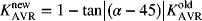 (7.23)
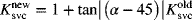
- Step 5: Set
 and return to step 2.
where ![]() .
.
Note that, the proposed method is applicable for any load/generation changes. However, as already mentioned for the positive phase deviations, the PSS gain must be increased instead of decreasing. In other words, for the positive phase deviations, that is, ![]() , Equation (7.21) will change to
, Equation (7.21) will change to
The flow chart representation of the proposed algorithm is shown in Fig. 7.18. Here, the KPSS, KAVR, and KSVC are the AVR, PSS, and SVC gains, respectively. In fact, the problem of a coordinated AVR–PSS design is reduced to the design of a simple switching/feedback-based method, which is quite easy for implementation.
Figure 7.18 Flowchart representation of the control strategy.
7.4.3 An Application Example
The capability of the proposed criterion and control strategy is investigated after application on several large-scale interconnected power systems. Here, this issue is illustrated using the New York/New England system, a 16-machine, 5-area test system, as shown in Fig. 4.4 (Chapter 4). As mentioned, all generators are represented by a two-axis model and equipped with PSS. The applied model for the AVR and PSS is shown in Fig. 4.5. The SVC block diagram is also presented in Fig. 7.19. The efficiency of the proposed control strategy is examined in the presence of wind turbines (WTs). To investigate the impact of WTs on the coordination problem, two wind farms are employed at buses 9 and 15. The implemented wind farms use simple squirrel cage induction generators without any control capability, which operate at a substantially constant speed, normally referred as the FSIGs [2] (Fig. 7.19).

Figure 7.19 The SVC block diagram.
7.4.4 Simulation Results
In Section 4.3, several disturbance scenarios in both generation and demand sides are applied to the considered case study and the importance of the Δδ–Δv graph in stability assessment is demonstrated. Here, the effectiveness of the introduced Δδ–Δv graph-based tuning approach for coordination of existing control devices (PSS, AVR, and SVC) to enhance oscillation damping and synchronization of the power system with and without wind power penetration are examined.
7.4.4.1 Case A: Without Wind Power
In the performed simulations without wind power penetration, the first sample is used at 1.5 s (TS1 = 1.5 s). First, the behavior of the power system after the outage of generator 12 is investigated. Note that without applying the proposed control strategy, as shown in Figs. 4.10 and 4.11, the system encounters transient instability, that is, first swing instability. The system response for this disturbance when using the explained tuning-based coordination strategy is shown in Fig. 7.20. The results demonstrate the efficiency of the proposed criterion and control strategy. Figure 7.20a shows the performance of the power system after applying the proposed control strategy within 4 s for the sake of comparison with the first swing instability without applying the strategy. It can be seen that the proposed control strategy aids the system to keep its transient stability. Figure 7.20b explains the behavior of the system within 30 s in the Δδ–Δv plane. It is clear that after a number of control reactions, the system conducts to a stable mode at the steady state. Distribution of the voltage–angle indexes in the normalized Δδ–Δv plane is also shown in Fig. 7.20. It can be seen that generators 14–16 are located in the PSS reaction region at the first control action. Therefore, decreasing the PSS gains of these generators besides decreasing the AVR gains for some others makes the system stable. It can be seen that the system response is quite improved using the proposed coordination methodology (Fig. 7.20d).

Figure 7.20 System response for the outage of generator 12 in the presence of the proposed control strategy: (a) time-domain results, (b)  graphs, (c) distribution of the normalized parameters in the
  plane at 1 s, and (d) at 13 s.
The simulation results show the satisfactory performance of the control strategy and success of the proposed criterion against the load changes as well as generation changes.
As another example, Fig. 7.21 shows the dynamics of the system after outage of generator 16. It can be seen that the system experiences disorders in the oscillatory, angle, and transient stability behavior during simulation time. The applied control strategy eliminates the voltage/rotor angle oscillations and conducts the system to a stable mode in the steady state. Note that without applying the proposed control strategy the system encounters instability. Distribution of the voltage–angle indexes related to the outage of generator 16 in the normalized (![]() ) plane is also shown in Fig. 7.21. At t = 1.5 s (Fig. 7.21c), except for two generators, the others are out of the desired region. According to the assigned control laws, by decreasing the PSS gains for this set of generators at the first control action, the system tries to keep its integrity. It can be seen that all the generators have been located in the desired region at the steady state (Fig. 7.21d).
) plane is also shown in Fig. 7.21. At t = 1.5 s (Fig. 7.21c), except for two generators, the others are out of the desired region. According to the assigned control laws, by decreasing the PSS gains for this set of generators at the first control action, the system tries to keep its integrity. It can be seen that all the generators have been located in the desired region at the steady state (Fig. 7.21d).


Figure 7.21 System response for the outage of generator 16 by applying the proposed control strategy: (a) time-domain results, (b)  graphs, (c) distribution of the normalized parameters in the
  plane at 1.5, 13, 57, and 95 s.
7.4.4.2 Case B: With Wind Power
Case B is performed to emphasize the efficiency of the proposed method for the power system in the presence of wind farms. In the performed simulations concerning wind power penetration, the TS1 will be fixed at 1.8 s. Figure 7.22 shows the dynamic response of the power system following outage of G12, concerning 8% wind power penetration. It can be seen that by the penetration of wind power, generators 14–16 try to be isolated from the system and operate in islanding mode. Therefore, the system is going into an unstable mode. The nonsimilar phase characteristics of generators besides the diverged terminals voltage behavior in Fig. 7.22b also exhibit instability of the system. Distribution of the voltage–angle indexes in the normalized (![]() ) plane is shown in Fig. 7.22c.
) plane is shown in Fig. 7.22c.


Figure 7.22 System response (with conventional control system) for the outage of generator 12 in the presence of wind power: (a) time-domain results, (b)  graphs, and (c) distribution of the normalized parameters in the
  plane at 1.8 s.
It can be seen that generators 14–16 are located in the operating region of the SVC. Therefore, the SVC should be implemented in the areas related to these generators. However, because of fewer deviations for generator 16 and taking into account the economic reasons, it seems that the SVC in this region could return the system to a stable mode. For this purpose, at the beginning of simulation, the SVC is considered in the model and after that, increasing of SVC gain improves the system performance.
The dynamic behavior of the power system after applying the proposed control strategy is shown in Fig. 7.23. The proposed control strategy conducts the system to a stable mode within several tuning steps. The initial and final values (controller gains at steady state) of control parameters are given in Table 7.2. Distribution of the normalized parameters in the proposed criterion for outage of G12 in the presence of wind farms and SVC can be seen in Fig. 7.23. From Fig. 7.23c, it is quite clear that all the generators are moved to the desired region at steady state.

Figure 7.23 System response for the outage of generator 12 following application of the proposed method in the presence of wind power: (a) time-domain results, (b)  graphs, and (c) distribution of the normalized parameters in the
  plane at 2, 4, 30, and 50 s.
Table 7.2 The Initial and Final Control Gains for Outage of G12
| PSS Gains (KPSS) | AVR Gains (KAVR) | SVC Gains (KSVC) | ||||
| Generator Number |
Initial | Final | Initial | Final | Initial | Final |
| 1 | 100 | 100 | 100 | 100.000 | – | – |
| 2 | 100 | 100 | 100 | 81.7805 | – | – |
| 3 | 100 | 100 | 100 | 80.2319 | – | – |
| 4 | 100 | 100 | 100 | 76.6451 | – | – |
| 5 | 100 | 100 | 100 | 75.1585 | – | – |
| 6 | 100 | 100 | 100 | 74.4325 | – | – |
| 7 | 100 | 100 | 100 | 76.0875 | – | – |
| 8 | 100 | 100 | 100 | 82.0945 | – | – |
| 9 | 100 | 100 | 100 | 80.1594 | – | – |
| 10 | 100 | 100 | 100 | 100.000 | – | – |
| 11 | 50 | 50 | 100 | 82.2249 | – | – |
| 13 | 110 | 110 | 100 | 81.7274 | – | – |
| 14 | 100 | 75.8369 | 100 | 64.7924 | – | – |
| 15 | 100 | 79.9705 | 100 | 64.8628 | – | – |
| 16 | 100 | 82.3612 | 100 | 81.5471 | 50 | 58.3413 |
7.4.4.3 Discussion
In the performed simulations, it was seen that in the transient period (based on the system inertia), interactions between the AVR and PSS gains improve the system performance and thereafter, reduction of AVR gains conducts the system to a stable mode. In other words, the PSSs contribute to maintain the transient stability. On the other hand, to avoid oscillatory instability, the torques in phase with rotor angle deviations, that is, AVRs gains, always decrease. The contribution of the PSS for keeping transient stability is discussed well by Kundur [27].
A practical discontinues excitation control (DEC), which employs switching strategy, was used at the Ontario hydro power plant to achieve stability and voltage regulation. The DEC addresses transient stability excitation control (TSEC) to improve stability. The TSEC is switched off from the system after 2 s (transient period) to avoid oscillatory instability. In other words, the DEC employs a fixed time-based switching strategy. However, the transient period can be varied from 2 s to about 10 s based on the system size and the mode status. Therefore, the fixed time-based switching strategy could affect the system performance.
The proposed algorithm in this section fulfills this concern by using an adaptive angle-based switching strategy. Based on the system operation, the synchronizing and damping torques are changed to achieve a satisfactory performance. Moreover, decreasing the AVR gains in the proposed control methodology eliminates probable subsynchronous resonance (SSR) in the system. It is shown that increasing the AVR gains could encounter a system with SSR [28]. For the present case study, the SSR phenomenon, which results from increasing AVR gains, is described in Ref. [2].
Due to the different kinds of uncertainty and parameter perturbation, load variations, and modeling errors, considerable efforts have been devoted to the design of robust excitation control. A conic programming method, which moves eigenvalues corresponding to the unstable and poorly damped modes to the left-hand side of the s-plane is introduced in Ref. [25]. In general, successfulness of all model linearization-based control methodologies severely depends on the relevant operating points. Considering various operating points, that is, the robustness issue, could degrade the controller performance by increasing the size of evaluation, control laws, and so on. However, the addressed graphical criteria in Chapter 4 and control strategy in the present section is absolutely independent of the operating point and hence, the robustness feature completely and successfully can be met. Moreover, the proposed control strategy relies on the basic power system equations and therefore it is applicable to any power system without any query. Simulation results prove the satisfactory performance of the control strategy under contingencies, as well as in normal conditions.
Simplicity of analysis using the developed graphical tool and model independency of the proposed coordinated control strategy can be considered as the main advantages of the present work.
7.5 Intelligent AVR and PSS Coordination Design
As mentioned before, following a disturbance in a power system, while a high-gain fast-response AVR improves the large-signal transient stability, it also has a detrimental effect on the oscillation stability and has a converse effect on the PSS operation for the transient stability. Therefore, in a fault situation it is necessary to have coordination between the two controllers.
This section presents the performance of intelligent fuzzy-based coordinated control for the AVR and PSS to prevent losing synchronism after a major sudden fault and to achieve appropriate postfault voltage level in multimachine power systems. The AVR and PSS gains are adaptively adjusted to guarantee the power system stability after faults.
To change AVR and PSS gains, one or more generators in each area must be equipped with the proposed fuzzy logic coordinator. The fuzzy logic unit accepts normalized deviations of terminal voltage and phase difference (described in Sections 4.2 and 7.4) as inputs and tunes AVR and PSS gains.
7.5.1 Fuzzy Logic-Based Coordination System
Figure 7.24a shows the overall scheme for the proposed fuzzy logic-based coordinator. The normalization and scaling blocks are not fuzzy variables and have been designed to improve the coordination performance. As shown, the fuzzy unit contains four major components: fuzzification, fuzzy rule-base, inference mechanism, and defuzzification.
Figure 7.24 (a) Fuzzy-logic-based coordinator. (b) Normalization method for the input signals.
Here, terminal voltage deviation and angle deviations are considered as input signals of the fuzzy system. These input signals are selected to guarantee the synchronism and stability enhancement of the power system. Furthermore, to limit the input signal deviations, a normalization method is applied. For this purpose, a method, which is conceptually shown in Fig. 7.24b, is used for both voltage and angle deviations. The Δδi−N (ΔVi−N) demonstrates the normalized phase difference (voltage deviation). The Δδi−N and ΔVi−N can vary in the range of [−1, 1] for all generators.
Fuzzification plays an important role in dealing with uncertain information, which might be objective or subjective in nature. The fuzzification block represents the process of making crisp quantity into fuzzy variables. In fact, the fuzzifier converts the crisp input to a linguistic variable using the assigned membership functions in the fuzzy knowledge base. Fuzziness in a fuzzy set is characterized by the membership functions. Using appropriate membership functions, the input/output quantities are converted to desirable linguistic variables, which finally specify the quality of control commands.
Here, the membership functions corresponding to the input variables are arranged as negative large (NL), negative small (NS), zero (ZR), positive small (PS) and positive large (PL), and for the output variables they are arranged as very small (VS), small (S), medium (M), and large (L). The number of membership functions for each variable may affect the quality of the output control command. In the present work, five membership functions are defined for the input signals and four membership functions are defined for output signals. The membership functions of input and output variables (for the case study shown in Fig. 6.8) are demonstrated in Fig. 7.25.
Figure 7.25 Membership functions for input signals and output signals (KAVR, KPSS).
The knowledge rule base consists of information for linguistic variables definitions (database) and fuzzy rules (control commands). The concepts associated with a database are used to characterize fuzzy control rules and a fuzzy data manipulation in the fuzzy logic controller. A lookup table is made based on discrete universes that define the output of a controller for all possible combinations of the input signals. A fuzzy system is characterized by a set of linguistic statements in the form of “if–then” rules. Fuzzy conditional statements make the rules or the rule set of the fuzzy controller. Finally, the inference engine uses the if–then rules to convert the fuzzy input to the fuzzy output.
Fuzzy inference is the kernel of a fuzzy logic system. With two inputs and five linguistic terms, 25 rules were developed for each output, which is given in Table 7.3 [17]. The antecedent parts of each rule are composed by using the AND function. Here, the Mamdani fuzzy inference system is employed. The centroid method is used for defuzzification.
Table 7.3 Fuzzy Rule Base for (a) PSS Gain and (b) AVR Gain
| (a) | ΔVN | ||||||
| KPSS | NL | NS | ZR | PS | PL | ||
| ΔδN | NL | VS | VS | VS | VS | S | |
| NS | S | S | S | M | M | ||
| ZR | S | S | M | M | M | ||
| PS | S | S | M | M | M | ||
| PL | M | L | L | L | L | ||
| (b) | ΔVN | ||||||
| KAVR | NL | NS | ZR | PS | PL | ||
| ΔδN | NL | VS | S | VS | VS | S | |
| NS | VS | S | S | VS | L | ||
| ZR | VS | S | S | S | L | ||
| PS | VS | S | S | S | M | ||
| PL | S | M | M | M | L | ||
7.5.2 Simulation Results
The efficiency of the fuzzy logic-based coordinated control for AVR–PSS is tested on the 2-area, 4-machine, 11-bus test system, which is shown in Fig. 6.8. The detailed bus data, line data, and dynamic characteristics for the machines, exciters, and loads are given in Ref. [27]. All generators use AVR and PSS controllers with the following transfer functions:
The power system has two areas with two generators in each area. The nominal system is operating with 413 MW being sent from area 1 to area 2. The AVR–PSS units of generator 2 in area 1 (connected to the swing bus in the system) and generator 4 at area 2 (with a high power rate) are considered to be coordinated/controlled by the designed fuzzy system.
Since, the time horizon for transient instability is almost about 3–5 s and this time horizon for small-signal instability is about 10–20 s, the fuzzy control unit will be activated in the system following 1 s after faults. As the first test scenario, the power system performance is investigated after outage of generator 3; and at the second test scenario, 1000 MW load has been suddenly added to the power system [17].
Outage of generator 3 can be accounted for as a severe fault in the present power system. Figure 7.26 shows the time domain responses of the generator outputs following a fault without the fuzzy coordinator system. Here, the Pa is accelerator power, Vt is terminal voltage and w is generator speed. Strong oscillations in accelerator powers are shown. It can be also seen that the power system loses its synchronism, and two areas are separated. Therefore, generator 4 cannot be able to supply whole the load in area 2 and voltage is collapsed in this area.
Figure 7.26 System generator response following outage of generator 4 without intelligent coordinator: (a) accelerator power, (b) terminal voltage, and (c) speed.
Figure 7.27 shows the system response (voltage, speed, and accelerator power) for the same fault in the presence of using a fuzzy logic system for tuning the AVR–PSS units in generators 2 and 4. The fuzzy systems maintain the synchronism and return the terminal voltages to the acceptable levels.

Figure 7.27 System generator response following outage of generator 4 with intelligent coordinator: (a) accelerator power, (b) terminal voltage, and (c) speed.
In the second test scenario, 1000 MW load step disturbance is applied to the system. The system responses without and with the proposed fuzzy logic-based coordination system are shown in Figs. 7.28 and 7.29. It is shown that using conventional AVR–PSS control, the system falls to an oscillatory instability and the synchronism is also lost. On the other hand, with the fuzzy logic-based coordination, the synchronism remains and the oscillations are successfully removed.

Figure 7.28 System generator response following 1000 MW load step increase without intelligent coordinator: (a) accelerator power, (b) terminal voltage, and (c) speed.
Figure 7.29 System generator response following 1000 MW load step increase with intelligent coordinator: (a) accelerator power, (b) terminal voltage, and (c) speed.
7.6 Summary
Power system stability and voltage regulation have been considered as important control issues for secure system operation over many years. Currently, because of expanding physical setups and penetration of RESs, the mentioned problems become more significant than in the past. Moreover, because of conflict behavior between stability and voltage regulation the successful achievement of both goals using independent control strategies is difficult.
In order to achieve stability and voltage regulation simultaneously, three control strategies using robust H∞ control, Δδ–Δv plot, and intelligent fuzzy system are addressed. The first control strategy is developed based on the H∞-SOF control technique via an iterative LMI algorithm. The proposed method was applied to a four-machine infinite bus power system, through the ANS laboratory real-time experiment, and the results are compared with a conventional AVR–PSS design. The performance of the resulting closed-loop system is shown to be satisfactory over a wide range of operating conditions. As shown in the nonlinear real-time simulation results, the proposed coordination through a new optimal feedback loop has brought a significant effect on improving the power system performance and widening the stable region.
The second control strategy uses a criterion in the normalized phase difference versus the voltage deviation Δδ–Δv plane. Based on the introduced criterion, an adaptive angle-based switching strategy and negative feedback are combined to obtain a robust control methodology against load/generation disturbances. The proposed method is applied to the IEEE 68-bus test system in the presence of wind power penetration. The obtained results based on the proposed control strategy exhibit satisfactory performance over a wide range of operating conditions.
As the third control scheme, a fuzzy logic-based coordination system for optimal tuning of AVR–PSS gains is introduced. The fuzzy system uses the normalized terminal voltage and phase angle deviations as input signals and generates the appropriate AVR and PSS gains. The closed-loop system performance is examined on the IEEE 11-bus test system.
The resulting controllers are not only robust but also allow direct effective trade-off between voltage regulation and damping performance. Furthermore, because of simplicity of structure, decentralized property, ease of formulation, and flexibility of design methodology, they are practically desirable.
References
- 1. H. Bevrani, T. Hiyama, and Y. Mitani, Power system dynamic stability and voltage regulation enhancement using an optimal gain vector, Control Eng. Pract., 16, 1109–1119, 2008.
- 2. H. Golpira, H. Bevrani, and A. H. Naghshbandi, An approach for coordinated automatic voltage regulator power system stabiliser design in large-scale interconnected power systems considering wind power penetration, IET Gen. Transm. Distrib., 6 (1), 39–49, 2012.
- 3. F. P. Demello and C. Concordia, Concepts of synchronous machine stability as affected by excitation control, IEEE Trans. Power Apparatus Syst., 88, 316–329, 1969.
- 4. G. Rogres, Power System Oscillations, Kluwer Academic Publishers, London, 2000.
- 5. V. A. Venikov and V. A. Stroev, Power system stability as affected by automatic control of generators: some methods of analysis and synthesis, IEEE Trans. Power Apparatus Syst., 90, 2483–2487, 1971.
- 6. H. M. Soliman and M. M. F. Sakar, Wide-range power system pole placer, Proc. Inst. Electr. Eng. C, 135 (3), 195–200, 1988.
- 7. O. P. Malik, G. S. Hope, Y. M. Gorski, V. A. Uskakov, and A. L. Rackevich, Experimental studies on adaptive microprocessor stabilizers for synchronous generators. In: IFAC Symposium on Power Systems and Power Plant Control, Beijing, China, 1986, pp. 125–130.
- 8. A. Heniche, H. Bourles, and M. P. Houry, A desensitized controller for voltage regulation of power systems, IEEE Trans. Power Syst., 10 (3), 1461–1466, 1995.
- 9. Y. Wang and D. J. Hill, Robust nonlinear coordinated control of power systems, Automatica, 32 (4), 611–618, 1996.
- 10. Y. Guo, D. J. Hill, and Y. Wang, Global transient stability and voltage regulation for power systems, IEEE Trans. Power Syst., 16 (4), 678–688, 2001.
- 11. N. Yadaiah, A. G. D. Kumar, and J. L. Bhattacharya, Fuzzy based coordinated controller for power system stability and voltage regulation, Electr. Power Syst. Res., 69, 169–177, 2004.
- 12. H. Bevrani and T. Hiyama, Stability and voltage regulation enhancement using an optimal gain vector. In: Proceedings of the IEEE PES General Meeting, Canada, 2006.
- 13. K. T. Law, D. J. Hill, and N. R. Godfrey, Robust controller structure for coordinated power system voltage regulator and stabilizer design, IEEE Trans. Control Syst. Technol., 2, 220–232, 1994.
- 14. K. T. Law, D. J. Hill, and N. R. Godfrey, Robust co-ordinated AVR-PSS design, IEEE Trans. Power Syst., 9, 1218–1225, 1994.
- 15. M. Saidy, A unified approach to voltage regulator and power system stabilizer design based on predictive control in analogue form, Electr. Power Energy Syst., 19, 103–109, 1997.
- 16. Y. Wang, D. J. Hill, R. H. Middleton, and L. Gao, Transient stability enhancement and voltage regulation of power systems, IEEE Trans. Power Syst., 8, 620–627, 1993.
- 17. R. Khezri and H. Bevrani, Fuzzy-based coordinated control design for AVR and PSS in multimachine power systems, 13th Iranian Conf. on Fuzzy Systems (IFCS), Qazvin, Iran, Aug. 2013.
- 18. C. Zhu, R. Zhou, and Y. Wang, A new nonlinear voltage controller for power systems, Int. J. Electr. Power, 19, 19–27, 1997.
- 19. A. M. El-Zonkoly, Optimal tuning of power systems stabilizers and AVR gains using particle swarm optimization, Expert Syst. Appl., 31, 551–557, 2006.
- 20. H. Boules, S. Peres, T. Margotin, and M. P. Houry, Analysis and design of a robust coordinated AVR/PSS, IEEE Trans. Power Syst., 13, 568–575, 1998.
- 21. Y. Y. Cao, J. Lam, Y. X. Sun, and W. J. Mao, Static output feedback stabilization: an ILMI approach, Automatica, 34 (12), 1641–1645, 1998.
- 22. D. Gautam, V. Vittal, and T. Harbour, Impact of increased penetration of DFIG-based wind turbine generators on transient and small signal stability of power system, IEEE Trans. Power Syst., 24, 1426–1434, 2009.
- 23. H. Bevrani, A. Ghosh, and G. Ledwich, Renewable energy sources and frequency regulation: survey and new perspectives, IET Renew. Power Gen., 4 (5), 438–457, 2010.
- 24. H. Bevrani and A. G. Tikdari, An ANN-based power system emergency control scheme in the presence of high wind power penetration. In: L. F. Wang, C. Singh, and A. Kusiak, editors, Wind Power Systems: Applications of Computational Intelligence, Springer Book Series on Green Energy and Technology, Springer, Heidelberg, 2010, pp. 215–254.
- 25. R. A. Jabr, B. C. Pal, and N. Martins, A sequential conic programming approach for the coordinated and robust design of power system stabilizers, IEEE Trans. Power Syst., 25, 1627–1637, 2010.
- 26. B. C. Pal and F. Mei, Modelling adequacy of the doubly fed induction generator for small-signal stability studies in power systems, IET Renew. Power Gen., 2, 181–190, 2008.
- 27. P. Kundur, Power System Stability and Control, McGraw-Hill, New York, 1994.
- 28. G. Rogers, Power System Oscillations, Kluwer Academic Press, Boston, MA, 1999.