
Appendix C
Four-Order Dynamical Power System Model and Parameters of the Four-Machine Infinite-Bus System
C.1 Four-Order Linearized Dynamical Model
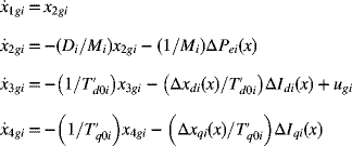
In order to design a robust power system controller, it is first necessary to find an appropriate linear mathematical description of the multimachine power system. In the viewpoint of “generator unit i,” the nonlinear state space representation model for such a system with two-axis model has the form
where the states
are defined as deviation from the equilibrium values
The nonlinear model of (C.1) can be presented as follows:
where

and

A detailed description of all symbols and quantities can be found in Ref. [1]. Using the linearization technique and after some manipulation, the nonlinear state (equations C.1) can be expressed in the form of following linear state space model.
where
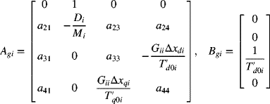
and
The above parameters are defined as follows:
| Machine rotor angle | |
| Machine rotor speed | |
| d-axis internal machine voltage | |
| q-axis internal machine voltage | |
| Damping constant | |
| Inertia constant | |
| Driving point conductance | |
| d-axis open-circuit transient time constant | |
| q-axis open-circuit transient time constant | |
| d-axis synchronous reactance | |
| d-axis transient reactance | |
| q-axis synchronous reactance |
The elements of ![]() matrix in (C.10) are
matrix in (C.10) are

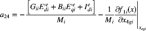

where

C.2 Four-Machine Infinite-Bus Power System
Table C.1 Generator Constants
| Unit No. | MVA | ||||||||
| 1 | 8.05 | 0.002 | 1.860 | 0.440 | 1.350 | 1.340 | 0.733 | 0.0873 | 1000 |
| 2 | 7.00 | 0.002 | 1.490 | 0.252 | 0.822 | 0.821 | 1.500 | 0.1270 | 600 |
| 3 | 6.00 | 0.002 | 1.485 | 0.509 | 1.420 | 1.410 | 1.550 | 0.2675 | 1000 |
| 4 | 8.05 | 0.002 | 1.860 | 0.440 | 1.350 | 1.340 | 0.733 | 0.0873 | 900 |
Table C.2 Line Parameters
| Line No. | Bus–Bus | |||
| 1 | 1–9 | 0.02700 | 0.1304 | 0.0000 |
| 2 | 2–10 | 0.07000 | 0.1701 | 0.0000 |
| 3 | 3–11 | 0.04400 | 0.1718 | 0.0000 |
| 4 | 4–12 | 0.02700 | 0.1288 | 0.0000 |
| 5 | 10–6 | 0.02700 | 0.2238 | 0.0000 |
| 6 | 11–7 | 0.04000 | 0.1718 | 0.0000 |
| 7 | 12–8 | 0.06130 | 0.2535 | 0.0000 |
| 8 | 9–10 | 0.01101 | 0.0829 | 0.0246 |
| 9 | 10–11 | 0.01101 | 0.0829 | 0.0246 |
| 10 | 11–12 | 0.01468 | 0.1105 | 0.0328 |
| 11 | 12–5 | 0.12480 | 0.9085 | 0.1640 |
Table C.3 Excitation Parameters
| 1.00 | 19.21 | 10.00 | 6.48 | 5.71 | 7.60 | −5.20 |
| 0.010 | 1.560 | 0.013 | 0.013 | 0.200 | 3.000 | 10.000 |
Table C.4 Governor and Turbine Parameters
| Parameters | Unit 1 | Unit 2 | Unit 3 | Unit 4 |
| 0.08 | 0.06 | 0.07 | 0.07 | |
| 0.10 | 0.10 | 0.10 | 0.10 | |
| 0.10 | 0.10 | 0.10 | 0.10 | |
| 0.40 | 0.36 | 0.42 | 0.42 | |
| 10.0 | 10.0 | 10.0 | 10.0 | |
| 0.05 | 0.05 | 0.05 | 0.05 | |
| 0.08 | 0.08 | 0.08 | 0.08 | |
| 0.58 | 0.58 | 0.58 | 0.58 | |
| 0.31 | 0.31 | 0.31 | 0.31 | |
| 0.24 | 0.24 | 0.24 | 0.24 | |
| 0.45 | 0.45 | 0.45 | 0.45 | |
| 0.50 | 0.50 | 0.50 | 0.50 | |
| 0.20 | 0.20 | 0.20 | 0.20 | |
| 1.50 | 1.50 | 1.50 | 1.50 | |
| −0.50 | −0.50 | −0.50 | −0.50 | |
| −0.20 | −0.20 | −0.20 | −0.20 | |
| −0.50 | −0.50 | −0.50 | −0.50 |
Table C.5 Conventional PSS Parameters
| 5.00 | 10.00 | 1.00 | 0.025 |
| 0.056 | 0.054 | 0.037 | 0.53 |
Reference
- 1. P. W. Sauer and M. A. Pai, Power System Dynamic and Stability, Prentice-Hall, Englewood Cliffs, NJ, 1998.