
Chapter 16. 3D Graphics
The 3D APIs in Windows Presentation Foundation are designed to be as approachable and easy to use as other parts of the .NET Framework. Because 3D is a truly integrated part of the WPF platform, many concepts are shared and reused from 2D graphics and elsewhere. This significantly reduces the learning curve for 2D developers approaching 3D for the first time because the 3D APIs often follow familiar patterns and conventions. WPF is therefore an excellent tool for learning about 3D graphics.
This chapter focuses primarily on the aspects of the APIs that are unique to 3D, but it is important to remember that much of the power of the 3D features comes from deep integration with the rest of the platform. This integration spans everything from user interface remoting, to printing, to running in partial-trust web applications.
Like 2D, the 3D features are available from both procedural code and XAML. To display a 3D scene in WPF, you build a graph of objects similar to the way you build 2D artwork out of Shapes or Drawings. Once you have described your scene, the system takes care of invalidation and repainting on your behalf. All the features of the property engine, such as data binding and animation, work identically with 3D objects.
3D content is not constrained to a box. Scenes contained within a Viewport3D are composed seamlessly with other UIElements and can be included in templates and ItemsControls. Likewise, 2D media such as video, Drawings, and Visuals can be displayed on the surfaces of 3D models. Services such as hit testing automatically continue into the 3D portions of the Visual tree.
This chapter has three purposes. First, it is an introduction to 3D graphics for developers who have no prior experience with 3D. Second, it is a reference for the 3D APIs in WPF. Third, it is a road map for experienced 3D developers familiar with other platforms, such as DirectX, or who need to write tools that interoperate with WPF.
Getting Started with 3D Graphics
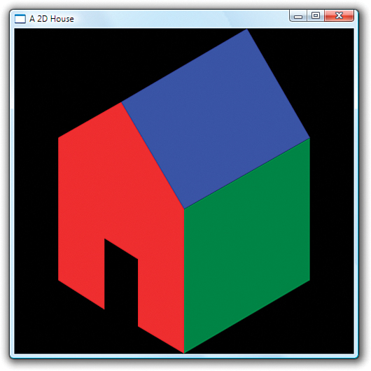
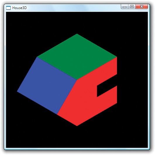
The purpose of 3D graphics is to produce 2D images from 3D models suitable for displaying on an output device such as a computer screen. Creating images from 3D models is a different paradigm than most 2D developers are used to. When working in two dimensions, you usually draw the exact shape that you want, using absolute coordinates. If you want a rectangle at (50,75) that is 100 units wide by 30 units tall, you typically create a Rectangle element (or a GeometryDrawing with a RectangleGeometry that has the corresponding bounds). Consider the house drawn in Listing 16.1 using the 2D Drawing classes. Figure 16.1 shows the output.
Figure 16.1 A simple house drawn using 2D Drawings.
Listing 16.1 Drawing a House with 2D Drawings

Although the house might have been drawn to look somewhat three-dimensional, the data from which the image was produced is two-dimensional. From the system’s point of view, you’ve drawn some flat 2D polygons. Although you can rotate the polygons within a 2D plane, you cannot turn the house to see the back or generate images of the inside of the house. No information exists for the parts of the house you cannot see. If you want to be able to create images of the house from multiple vantage points (without creating independent 2D drawings for each view), you have to give the system more information.
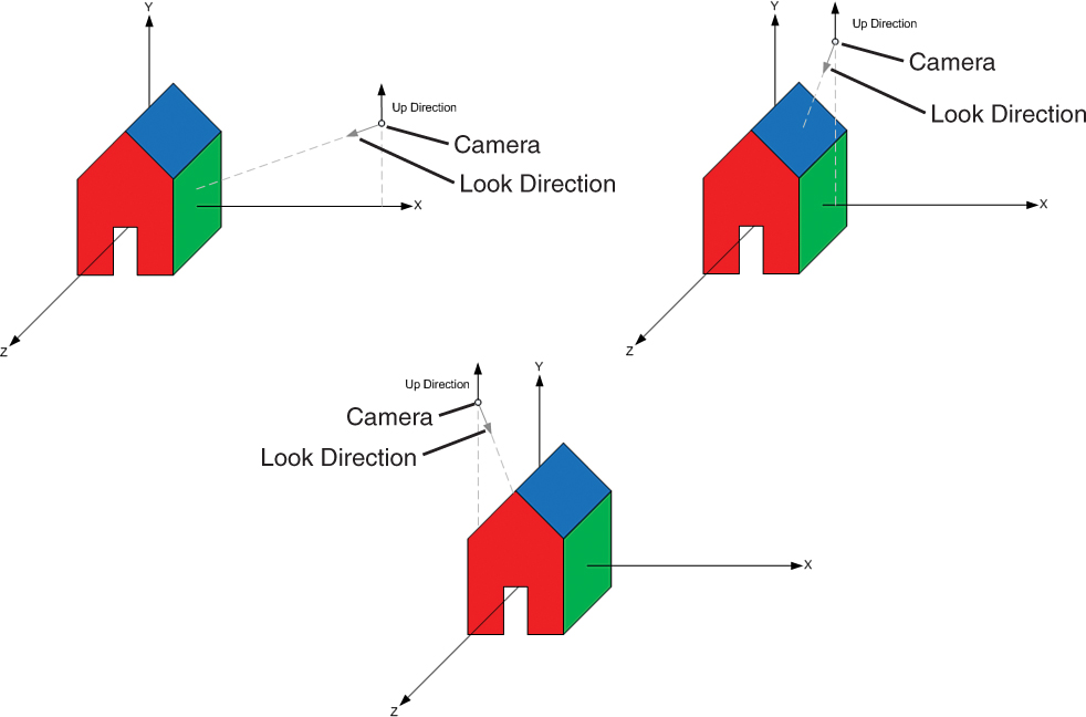
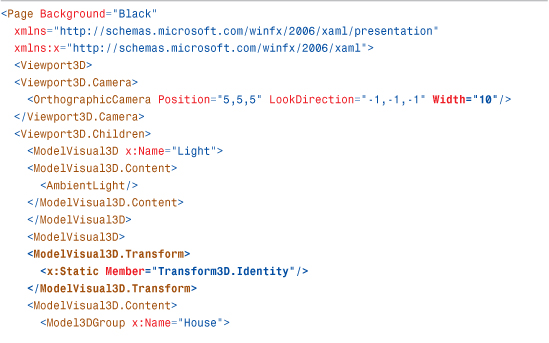
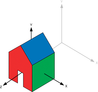
Listing 16.2 gives a preview of how the same image would be produced using Model3Ds instead of 2D Drawings. Although Listing 16.2 is longer than its 2D counterpart, it provides a great deal more flexibility in what you can do with your house. Using the 3D model, you can now generate 2D images from any vantage point just by tweaking a few properties, as shown in Figure 16.2.
Figure 16.2 Several views of the house.

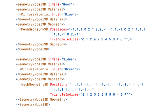
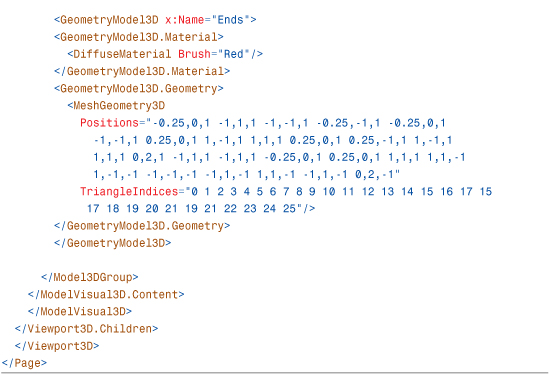
Listing 16.2 A House Drawn Using Model3Ds

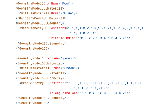

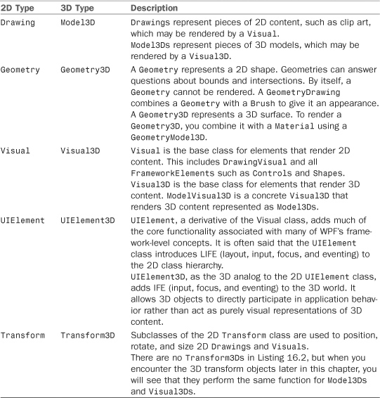
Listing 16.2 gives you a peek at most of the objects that are discussed in the remainder of the chapter. While many of the classes in the listing are new, they are straightforward extensions of the 2D types covered in Chapter 15, “2D Graphics.” Table 16.1 shows how some of the 3D types map to their nearest 2D equivalents.
Table 16.1 Mapping 2D Types to the Nearest 3D Equivalent
While most of the 3D objects are straightforward extensions of the 2D API, there are two concepts that are unique to 3D in WPF and also appear in Listing 16.2:
• Cameras—To generate images of 3D models, you place a virtual Camera within the scene. As with a real camera, the position, orientation, and other properties of the Camera determine your view of the scene.
• Materials and Lights—In 2D, you use Brushes to specify the appearance of a filled Geometry. In 3D, you also use Brushes, but there is an extra lighting step that influences the appearance of 3D surfaces.
As you will see in the upcoming sections, the Camera, Materials, and Lights all play important roles in enabling you to quickly render views of dynamic 3D scenes.
Cameras and Coordinate Systems
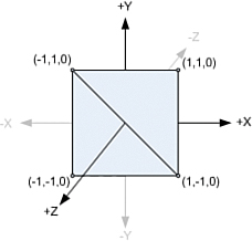
In the real world, what you see depends on where you stand, the direction you look, how you tilt your head, and so on. In WPF, you place a virtual Camera into your 3D scene to control what will appear in the Viewport3D. This is done by positioning and orienting the Camera in the world coordinate system (sometimes called world space for short). Figure 16.3 shows the 2D and 3D coordinate systems that WPF uses.
Figure 16.3 The 2D and 3D coordinate systems.
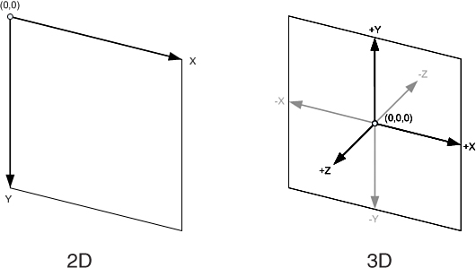
Besides the extra z-axis, a couple additional differences exist between the 2D and 3D coordinate systems.
In 3D, the y-axis typically points up instead of down. Also, negative coordinates, which are rarely used in 2D, are quite common in 3D. Because of this, you usually consider the origin to be at the center of space as opposed to the top-left corner, as you do in 2D. Of course, these are merely conventions, and you are free to use transformations to map into whatever system is most convenient for you.
The two common Camera classes you will use, OrthographicCamera and PerspectiveCamera, expose a set of properties to position and orient your Camera in world space. The upcoming sections discuss these properties and how you can use them to control what part of the 3D scene is visible.
Position
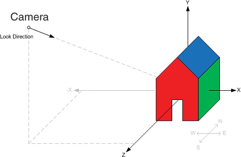
The Position property controls where the Camera is positioned in space. By moving the Camera, you can create different views of a scene. The Position property is of type Point3D. Point3Ds contain x, y, and z coordinates and define a location in a coordinate system. When rendering the model of the house, Listing 16.2 used the position (5,5,5):
![]()
Digging Deeper: WPF Uses a Right-Handed Coordinate System
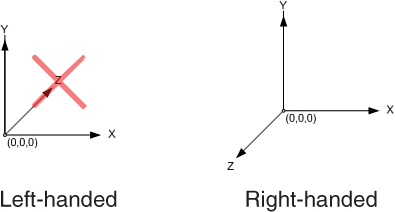
The handedness of a coordinate system refers to the relationship of the z-axis to the x- and y-axes. If the positive x- and y-axes are arranged as shown in Figure 16.4, there are two directions the z-axis could point. In a left-handed coordinate system, the positive z-axis points away from the viewer, as shown on the left. In a right-handed system, the positive z-axis points toward the viewer, as shown on the right.
Figure 16.4 Left-handed versus right-handed coordinate systems.
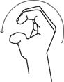
WPF standardized on a right-handed coordinate system. The right-handed coordinate system derives its name from the right-hand rule: If your index finger points in the direction of the positive x-axis and your middle finger points in the direction of the positive y-axis, your thumb indicates the direction of the positive z-axis, as shown in Figure 16.5.
Figure 16.5 The right-hand rule.
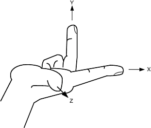
This is an easy, if not somewhat awkward, way to remember the relationship between the axes. Later in this chapter, you’ll discover a different version of the right-hand rule to remember the winding order of triangles in a MeshGeometry3D.
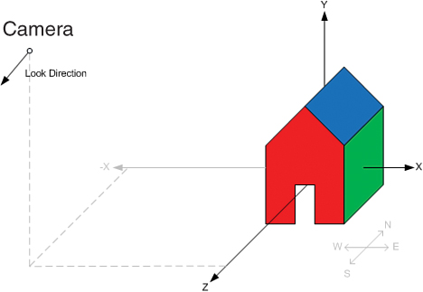
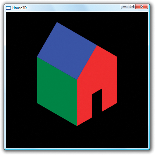
This means that the Camera is positioned five units to the right on the x-axis, five units up on the y-axis, and five units forward on the z-axis. Looking at Figure 16.6, you can see that this locates the Camera above the house, looking at what we will call the southeast side. (There is no standard connection between the axes and the cardinal directions, but you can assign one for your application for convenience.)
Figure 16.6 Camera positioned to view the southeast side.

If you wanted to see the southwest side of the house, you would position the Camera at (-5,5,5):
![]()
The new position is shown in Figure 16.7.
Figure 16.7 Camera positioned to view the southwest side.

However, setting the Camera to this new position alone would not give you the desired view without adjusting the LookDirection. To use a physical analogy, this is like looking at your friend through the viewfinder of a camera and then taking 10 giant steps to the left. Unless you turn to face your friend again, you will now be taking a picture of the wall. You use the LookDirection property to control which direction the Camera is looking.
LookDirection
The LookDirection property specifies which direction the Camera is facing. LookDirection is of type Vector3D. Like Point3Ds, Vector3Ds also contain x, y, and z coordinates, but rather than specify a location in space, a Vector3D specifies a direction and a magnitude. The magnitude of a Vector3D is called its Length and is given by
![]()
Warning: Remember, Cameras have a blind spot!
Surfaces closer than the Camera’s NearPlaneDistance will be clipped. When setting the Camera’s Position, you need to be careful that any objects you want to see are at least NearPlaneDistance units ahead of the Camera in the LookDirection. Figure 16.8 shows what would happen if you moved the Camera too close to the model of the house.
Figure 16.8 House clipped by the Camera’s near plane.

The purpose of a Camera’s NearPlaneDistance is to work around the limited floating-point precision of the GPU’s Z buffer. When the precision of the Z buffer is exhausted, a phenomenon known as Z-fighting occurs, in which the GPU is unable to determine which surfaces are nearer to the Camera. Figure 16.9 shows an example of the type of rendering artifacts Z-fighting causes. The pattern of the artifacts usually changes with the viewing angle.
Figure 16.9 Z-fighting artifacts.
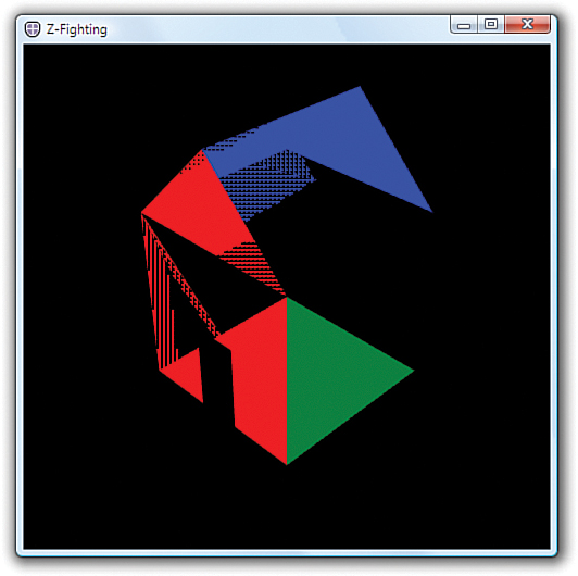
Z-fighting is typically caused by attempting to render objects too close to the Camera’s Position. The NearPlaneDistance property of the Camera works around Z-fighting by clipping objects closer than a certain distance from the Camera. NearPlaneDistance defaults to 0.125, which is a good setting.
There are other, less common, ways that Z-fighting may occur. One is attempting to render objects that are really far away from the Camera. There is a corresponding FarPlaneDistance, which can be used to work around this if it occurs, but because it is rare, this property defaults to positive infinity.
Finally, Z-fighting can occur when you render two surfaces that are nearly, but not quite, on top of each other. The only way to fix this case is to move the surfaces sufficiently far apart, such that one is clearly closer to the Camera than the other. If two surfaces are exactly on top of each other, however, the rendering order is deterministic, and Z-fighting will not occur. In this case, the surface rendered second will always appear on top.
The Camera in Listing 16.2 uses a LookDirection of <-1,-1,-1>:
![]()
The x, y, and z coordinates of this vector tell the camera to look downward, toward the northwest, as shown in Figure 16.10.
Figure 16.10 Camera looking downward, toward the northwest.

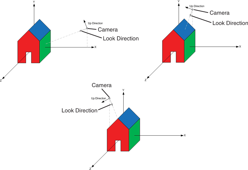
It was mentioned previously that if you moved the Position of the Camera to (-5,5,5), the house would no longer be visible. Figure 16.11 shows you why. Moving the Camera does not change the LookDirection, so the Camera is no longer facing the house in its new location.
Figure 16.11 Moving the Camera does not change the LookDirection.
An easy way to figure out the required LookDirection for the Camera is to find a point in world space that you want to see and subtract it from the Camera’s Position. In this case, the model of the house is roughly around the origin (0,0,0). Subtracting (-5,5,5) from (0,0,0) gives a vector in the direction of <5,-5,-5>, as shown in Figure 16.12.
Figure 16.12 The new LookDirection.
Using this new LookDirection generates the image in Figure 16.13:
![]()
Figure 16.13 Viewing the other side of the house.
Tip
WPF APIs that take a Vector3D to indicate direction are only interested in the direction of the Vector3D, not the Length. A LookDirection of <1,-1,-1> produces an identical image to the one shown in Figure 16.13. If the Length of the Vector3D needs to be normalized for internal calculations, WPF does this for you automatically.
In general, you only need to be concerned that Vector3Ds define a direction (that is, they are not the zero vector <0,0,0>), unless you are using them to calculate Point3Ds. When adding a Vector3D to a Point3D to find a new Point3D, the Length determines how far away the new Point3D will be. You should be aware that the Length of Vector3Ds influences the direction during linear interpolation. Specifically, Vector3DAnimation does not normalize the Vector3Ds first.
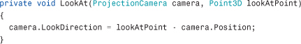
If you are moving the Camera a lot, it might make sense to write a small utility method to assign the new LookDirection for the Camera based on its Position and the point you want to look at:
UpDirection
The LookDirection tells which direction the Camera is facing, but this does not completely specify the Camera’s orientation. You can still twist the Camera while keeping the LookDirection fixed on the same point in space, as shown in Figure 16.14. This is what you do with a physical camera to go from landscape to portrait orientation. You can use the UpDirection property to disambiguate this final component of the Camera’s orientation.
Figure 16.14 The UpDirection property.

The UpDirection property defaults to <0,1,0>. By specifying a different direction, such as <1,0,0>, you can turn the Camera on its side. Figure 16.15 shows the image produced with this UpDirection.
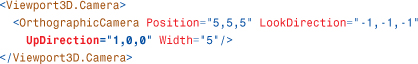
Figure 16.15 Specifying the positive x-axis as the UpDirection.
In this section, you manipulated the Camera in the scene by using the Position, UpDirection, and LookDirection properties. Although this is often the most convenient way to set up a static Camera in a scene, most scenarios that involve moving or rotating the Camera are more easily accomplished by using the Camera.Transform property.
Tip
The Camera.Transform property is especially helpful if you want the Camera to follow an object moving through the scene because the same Transform3D can be applied to both the Camera and the object you want to follow.
The key advantage of the Camera.Transform property is that it enables the Camera to be positioned and animated like other 3D objects in the scene. Keep this in mind when Transform3Ds are discussed later in this chapter.
Warning: Don’t forget to transform the UpDirection!
If you are rotating the Camera around an object and the view abruptly flips over as you pass a certain spot, chances are that you forgot to adjust the UpDirection. The trouble happens if you move the LookDirection past the UpDirection, as shown in Figure 16.16.
Figure 16.16 Camera passing over the house incorrectly.
As the Camera approaches the house, the LookDirection is adjusted so that you are looking downward. As the Camera goes over the roof, you would expect to be looking at the far side of the house upside down. However, because UpDirection is still pointing at the positive y-axis, the Camera instead spins in place right as you cross the center of the roof. Worse, when you are directly above the roof, the LookDirection and UpDirection are on the same line and the result is undefined. The correct way to rotate the Camera like this is to rotate the UpDirection along with the LookDirection, as illustrated in Figure 16.17.
Figure 16.17 UpDirection adjusted to preserve view as Camera passes house.
OrthographicCamera Versus PerspectiveCamera
WPF has two types of Cameras that most applications choose from. The PerspectiveCamera creates a realistic image in which objects farther from the Camera appear smaller than those closer to the Camera. This models the way humans see things in the real world. The other type of Camera, OrthographicCamera, is more useful for editing tools and some visualizations because objects appear the same size, regardless of their distance from the Camera, allowing for precise measurement and analysis. Technical and manufacturing drawings frequently use OrthographicCameras. Figure 16.18 shows the same model rendered with an OrthographicCamera and a PerspectiveCamera.
Figure 16.18 OrthographicCamera and PerspectiveCamera examples.

All Cameras work by projecting the 3D models in the scene onto an image plane that is then displayed to the user. With an OrthographicCamera, each point on the image plane shows what is straight behind it, as shown in Figure 16.19. This enables you to view a section of space shaped like a rectangular right prism. The width of the viewable space is controlled by the OrthographicCamera.Width property. The height is computed automatically from the Viewport3D’s bounding rectangle to preserve an aspect ratio of 1:1. Here is OrthographicCamera in action:
![]()
Figure 16.19 Orthographic projection.

With a PerspectiveCamera, the width of the viewable area is not constant. As the distance from the Camera increases, more of the 3D world space is visible. This enables you to view a square frustum-shaped region of the scene, as shown in Figure 16.20. Because the viewable area expands as you get farther from the Camera, objects farther away appear smaller in a perspective projection. You control the rate of expansion with the FieldOfView property. In WPF, FieldOfView controls the horizontal angle at which the field of view expands. Here is PerspectiveCamera in action:
![]()
Figure 16.20 Perspective projection.
The FieldOfView property is comparable to the zoom lens on a physical camera. The Width property is the analogous concept for an OrthographicCamera. Small values for Width and FieldOfView “zoom in” on a small part of a 3D object. Larger values of Width and FieldOfView show more of the scene.
Transform3D
As with Transforms in 2D, Transform3Ds allow you to position, rotate, and size 3D objects in space. Transform3Ds can be applied to Model3Ds, ModelVisual3Ds, and the Camera. This is done by setting their respective Transform properties. When you set the Transform property on a 3D object, you are mapping your object’s coordinate space into a new coordinate space. This is no different than what happens when you position an element in 2D by using the Canvas.Left and Canvas.Top properties.
Figure 16.21 displays the 2D drawing of a ghost from Chapter 15. All the drawing instructions that make up the ghost are relative to the ghost’s local coordinate system. Using a 2D TranslateTransform, you can change the ghost’s frame of reference so that the point (0,0) in the ghost’s coordinate system is no longer the same as point (0,0) in the container’s coordinate system. This is shown on the right side of Figure 16.21.
Figure 16.21 The ghost’s coordinate system versus the container’s coordinate system.

The TranslateTransform causes the ghost and any child Visuals it might contain to move on the screen, but as far as the ghost is concerned, it’s business as usual. None of the ghost’s drawing instructions are modified, just its frame of reference. This is actually how a Canvas moves elements around—by constructing a TranslateTransform for its contained Visuals behind the scenes.
The same principles apply to 3D transforms. In 3D, there is a top-level world coordinate system. To position, size, and orient 3D objects within the world coordinate system, you use the five subclasses of Transform3D:
• TranslateTransform3D—Offsets a 3D object relative to its container.
• ScaleTransform3D—Scales a 3D object relative to its container.
• RotateTransform3D—Rotates a 3D object relative to its container.
• MatrixTransform3D—Transforms a 3D object by a Matrix3D.
• Transform3DGroup—Contains a collection of Transform3Ds. The Transform3DGroup is itself a Transform3D and is used to apply multiple transforms to a 3D object.
This section applies these transforms to the simple model of a house shown at the beginning of this chapter. Listing 16.3 presents the same XAML as before, except with two emphasized changes. First, it has an added transform (currently the identity transform which does nothing). Second, it has an increased Width for the Camera so that you’ll be able to see the effect of applying various transforms.
Listing 16.3 Updates to the House Drawn Using Model3Ds
TranslateTransform3D
TranslateTransform3D moves an object by an offset relative to its container. The offset is specified by the OffsetX, OffsetY, and OffsetZ properties. For example, setting the OffsetZ property to 3 slides the house forward on the z-axis by three units, as shown in Figure 16.22:
![]()
Figure 16.22 Translating the house forward three units on the z-axis.
Note that you can position 3D objects more easily by constructing your models such that the origin is at a convenient location. For example, the house model has the origin roughly at the center. To move the house so that the center is at the point (3,2,1), you can translate it as follows:
![]()
ScaleTransform3D
ScaleTransform3Ds are used to change the size of 3D objects. The scale factor is expressed in each dimension by the ScaleX, ScaleY, and ScaleZ properties. Because you can specify different scale factors for each dimension, it is possible to stretch an object using a ScaleTransform3D. For example, the following transform makes the house twice as wide along the x-axis, as shown in Figure 16.23:
![]()
Figure 16.23 Scaling the house along the x-axis.

Warning: Scale by 1, not 0, when you want to keep the original size!
To keep an object at its original size, you want a 1:1 scale—not a 1:0 scale. Setting ScaleX, ScaleY, or ScaleZ to 0 flattens the object in one or more directions. Flattening in one dimension can sometimes be useful—for example, to flatten a sphere into a disk. But flattening in two dimensions collapses the 3D object into an invisible line, and flattening in three dimensions reduces the object to an invisible point!
To change the size of a 3D object while maintaining its proportions, set the ScaleX, ScaleY, and ScaleZ properties to the same value. This is called a uniform scale. A uniform scale factor of 2 doubles the size of an object. A uniform scale factor of 0.5 halves the size of an object.
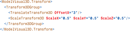
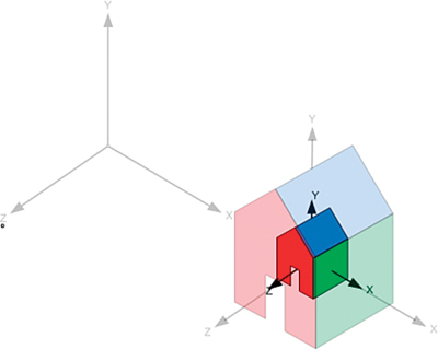
When you apply a scale, you are expanding and contracting space. This causes all points to move except for the center of the scale. By default, this center is the origin. In Figure 16.23, the house remained in place because the center of the house is the origin. If you moved the house so that the center is at (0,0,3) and then scaled it to half the size, the center of the house would move to (1.5,0,0) as space contracted toward the origin. This is shown in the following XAML, and the results are shown in Figure 16.24:
Figure 16.24 The house moves as space contracts toward the origin.

One way to prevent the house from moving during the scale is to specify a different point in space to be the center of the scale. You do this by setting the CenterX, CenterY, and CenterZ properties. The following XAML illustrates how to do this by choosing the scale center to be the new center of the house:
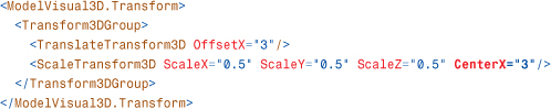
This causes the house to shrink “in place,” as shown in Figure 16.25.
Figure 16.25 The scale is centered at the center of the house.
Another way to keep the house from moving is to reorder the translate and scale transforms:
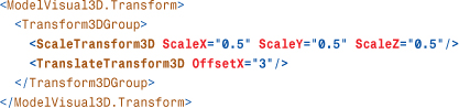
If you perform the translation after the scale, the scale does not affect the offset of the translation. This is because the house is first shrunk while it is still at the origin. After the house is the desired size, it is then moved three units on the x-axis.
Looking at Figure 16.24, you might have noticed that as the scale factor approaches zero, the house moves toward the center of the scale. You might wonder what happens if the scale factor goes past zero to negative numbers. This causes the object to be reflected. Figure 16.26 shows how a negative ScaleZ causes the house model to be mirrored in the XY plane:
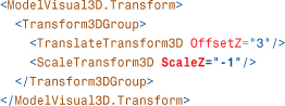
Figure 16.26 Reflecting along the z-axis.

Notice that the reflection changes the direction of the z-axis. If you were to apply a translation after the scale, the OffsetZ property would now move the object in the opposite direction.
RotateTransform3D
RotateTransform3Ds are used to rotate 3D objects in space. The rotation is described by a Rotation3D object. Rotation3D is an abstract class with two concrete implementations:
• AxisAngleRotation3D—Rotates the object around the specified Axis by the number of degrees given by the Angle property. This is usually the most convenient and human-readable way to describe 3D rotations.
• QuaternionRotation3D—Specifies the rotation as a Quaternion. Quaternions are a clever encoding of an Axis/Angle rotation with some nice properties that make them popular with many 3D systems and tools.
FAQ
![]() Why doesn’t WPF standardize on one way to specify rotations?
Why doesn’t WPF standardize on one way to specify rotations?
Early releases of WPF had support for only Quaternions, but Quaternions turned out to be difficult for 2D developers approaching 3D for the first time. A common mistake was to create a rotation from 0 to 360°, which resulted in no movement during a Rotation3DAnimation because it started and ended in the same orientation. Rotating an object more than 179.9999...° required either cumulative animations or multiple key frames.
Later WPF releases added Axis/Angle rotations to make the trivial spinning-in-place animation easier for developers new to 3D. A simple spin could then be created by animating the Angle property with a DoubleAnimation. However, support for Quaternions was kept as an aid for people writing exporters for modeling packages that often represent rotations as Quaternions.
To support “layout-to-layout” animations where you might have defined one rotational configuration using Axis/Angle and another using Quaternions, WPF derives AxisAngleRotation3D and QuaternionRotation3D from the common Rotation3D base class. You can animate between any two Rotation3Ds using a Rotation3DAnimation, which always takes the shortest path between the two orientations.
One form of rotation not directly supported by WPF is Euler angles. An Euler angle rotation takes the form of three angles that represent rotations about three axes. Which three axes, the order in which the rotations are applied, and the direction of the rotation are not standardized.
There is no EulerAngleRotation3D in WPF, but you can construct an equivalent Transform3D by using a Transform3DGroup containing three RotateTransform3Ds, as in the following XAML:
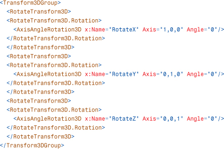
Note that you might need to tweak the axes to match the ordering you want.
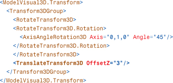
Figure 16.27 shows the result of rotating the house model 45° around the y-axis, as follows:

Figure 16.27 Rotation of 45° about the positive y-axis.
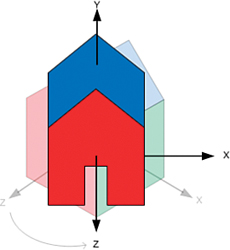
In a right-handed coordinate system, a positive angle of rotation rotates the coordinate space counterclockwise.
Note that after the rotation, the x- and z-axes are pointing in new directions. If you had applied a translation prior to the rotation, as follows, you would have encountered behavior similar to what was observed with the ScaleTransform3D:

Rotations rotate space around a point. By default, that point is at the origin. If your model is not centered at the point of rotation, you will find it has moved, as shown in Figure 16.28.
Figure 16.28 Side effect of the rotation.

Again, if you want the house to spin “in place,” one option is to change the center of rotation, using the CenterX, CenterY, and CenterZ properties:

Another way to work around this is to reorder the translate and rotate transforms. If you perform the translation after the rotation, the rotation does not affect the offset of the translation:
Combining Transform3Ds
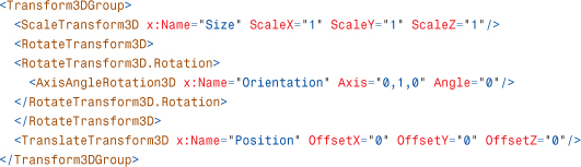
Unlike in 2D, where the common case is to apply just a translation, the common case in 3D is to apply three transforms: scale, rotate, and translate (generally in that order). To apply multiple transforms, use a Transform3DGroup. The following XAML shows the typical usage of a Transform3DGroup:
Model3D
Model3Ds are the building blocks out of which you build a 3D model for a scene. Multiple Model3Ds are often grouped together to make a single 3D model. The Model3D classes are analogous to the 2D Drawing classes. However, unlike in 2D, where using Drawings is one of many ways to add 2D content to a WPF application, using Model3D is the only way to declare 3D content in WPF.
WPF includes three subclasses of Model3D:
• Light—Has several subclasses that emit light into the scene. It is often overlooked that Lights are, in fact, Model3Ds, which is very convenient for scenarios such as attaching the headlights to a car with a Model3DGroup.
• GeometryModel3D—Renders a surface (described as a Geometry3D) with a given Material. GeometryModel3D is analogous to the 2D GeometryDrawing.
• Model3DGroup—Contains a collection of Model3Ds. The Model3DGroup is itself a Model3D and is often used to group multiple GeometryModel3Ds and Lights into a single 3D model.
You have already seen all these classes in use in Listings 16.2 and 16.3, which rendered the simple house.
Tip
Entering XAML by hand is very educational and might be useful for creating simple models or “stand-in” art such as cubes, but it’s not a good long-term strategy for creating 3D models.
Just as most bitmaps are created in a paint program, most 3D models are created using modeling software. Those that are not modeled in an application are usually generated procedurally.
When you need shapes more complex than planes and cubes, you should use a 3D modeling program with a XAML exporter. Numerous third-party exporters for the most popular 3D modeling packages exist, including some free packages. There are also 3D modeling programs such as Electric Rain’s ZAM 3D, which are explicitly targeted at WPF and use XAML natively.
Lights
Lighting is a concept that is unique to 3D in WPF. In 2D, the colors that appear from the screen usually come directly from the Brush or Pen used. In 3D, there is an extra lighting step, which dynamically calculates the shading of the 3D objects, depending on their proximity to light sources in the scene. Dynamic lighting makes it far easier to create and animate realistic-looking scenes.
There are three components to lighting: Light objects, which emit light into the scene, Materials, which reflect the light back to the Camera, and the Geometry of the model, which determines the angles involved. This section introduces the various Light types supported by WPF:
• DirectionalLight—Casts parallel rays into the scene from an origin at infinity. DirectionalLight approximates a far-away light source such as the sun.
• PointLight—Radiates light uniformly in all directions from a point in the scene. The intensity of the light attenuates as distance from the point increases. PointLight approximates unfocused light sources such as light bulbs.
• SpotLight—Emits a cone of light from a point in the scene. As with PointLight, the intensity of the light attenuates as distance from the point increases. SpotLight approximates focused light sources such as the beam of a flashlight.
• AmbientLight—Lights every surface uniformly. A bright AmbientLight creates flat-looking images because of lack of shading, but a low-intensity AmbientLight approximates the effect of light that has been scattered by reflecting between diffuse surfaces in the scene.
You might have noticed that each of the previous descriptions contains the word approximates. It’s important to understand that the goal of lighting in real-time graphics systems such as WPF is not to produce an accurate physical simulation of the way light behaves in the real world. To achieve real-time frame rates, graphics systems use clever tricks and rough estimations. Two common approximations are that surfaces do not block light (that is, they do not cast shadows) and lighting is computed only at the vertices of a mesh and then is interpolated across the face. WPF uses both of these approximations.
There is an element of artistry in creating a scene that appears to be realistically lit. To accomplish the desired effect, you might need to do unrealistic things such as add extra light sources, bake lighting effects into your Materials, and so on. Don’t feel bad about doing these things. Although the lighting and material APIs use real-world metaphors, they are just tools.
DirectionalLight
A DirectionalLight approximates a light source so far away that the rays have become parallel, such as light from the sun striking the Earth. Figure 16.29 illustrates the effect of the following DirectionalLight shining down on a sphere:
![]()
Figure 16.29 DirectionalLight shining on a sphere.

The direction of the light entering the scene is controlled by the Direction property. Of course, the Transform property inherited from Model3D also influences the direction of the light. The color of the Light is controlled by the Color property.
Tip
You can control the intensity of lights by using the Color property. For example, #FFFFFF is a full-intensity white light. #808080 is a half-intensity white light. The alpha component of the light color has no effect.
Lights work additively. For example, two identical (same Position, same Direction, and so on) half-intensity lights yield the same effect as one full-intensity light.
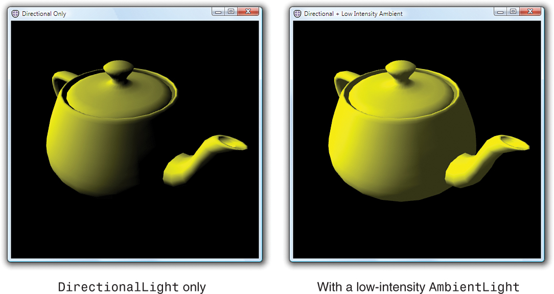
Images created with a single DirectionalLight often look somewhat unnatural, and for good reason. In the real world, even when light enters a scene from a single direction (as does sunlight), it generally bounces around between objects in the scene, causing some illumination. One way to approximate this is to add a low-intensity AmbientLight, covered later in this section.
PointLight
A PointLight approximates a light source that radiates light uniformly in all directions from a point in space, such as a naked light bulb. Unlike a DirectionalLight, the intensity of the light from a PointLight diminishes as distance from its position increases. Figure 16.30 illustrates the effect of the following PointLight illuminating a nearby sphere:

Figure 16.30 PointLight shining on a sphere.
The location of a PointLight is specified by its Position property. The rate at which the light intensity attenuates as distance increases is controlled by a combination of the ConstantAttenuation, LinearAttenuation, and QuadraticAttenuation properties.
The formula for attenuation is
![]()
where C, L, and Q are ConstantAttenuation, LinearAttenuation, and QuadraticAttenuation, respectively. d is the distance between the Light’s position and the point being lit. You can derive some useful information from this formula. For example, C=1, L=0, Q=0 gives you a PointLight with constant intensity, regardless of distance. However, these properties are usually set by trial and error.
PointLights also have a Range property, which specifies an abrupt cutoff radius outside of which the PointLight has no effect. Range is unrelated to the attenuation properties in that it does not affect the intensity of the light inside of the cutoff. The default value of Range is positive infinity.
SpotLight
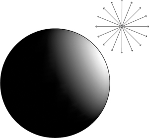
SpotLights are PointLights that have been focused into a beam. In the real world, light is focused using lenses and reflectors. In real-time computer graphics, this is approximated by limiting the emissions from a PointLight to a cone. Figure 16.31 shows how a SpotLight is just a PointLight whose rays have been constrained to an angular spread.
Figure 16.31 SpotLight shining on a sphere.
FAQ
![]() Why doesn’t my
Why doesn’t my SpotLight or PointLight light my model?
The beginning of this section mentions that real-time lighting uses clever tricks and rough estimations to achieve real-time frame rates. One of the approximations that WPF uses is to compute the intensity of lights only at the vertices.
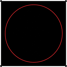
This approximation can sometimes causes surprising results with PointLights and SpotLights, as shown in Figure 16.32. The red circle shows where the light intersects the quadrilateral. This could be either the cone of a SpotLight or the lit sphere of a PointLight with limited Range. The surface remains unlit because the light did not extend to the vertices at the corners.
Figure 16.32 Light inside a quadrilateral.
To work around this, the surface can be subdivided into a grid of quadrilaterals, as shown in Figure 16.33. Adding vertices increases the number of sample points at which lighting is computed, and you will begin to see the effect of the SpotLight.
Figure 16.33 Light inside a subdivided grid.

As you continue to subdivide the mesh, the detail increases. However, to create a perfect circle of light, you need to subdivide until you have about one vertex per pixel.
If you have a reasonably sized falloff area similar to the one shown in Figure 16.31, a small number of subdivisions usually does the trick. If you need a hard boundary between your lit and unlit areas, it might be better to bake the lighting into your Material. This can work especially well if the lighting in your scene is static.
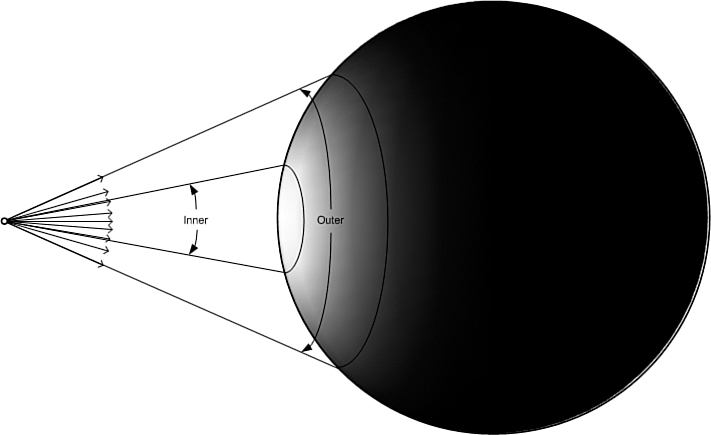
The Direction property specifies the direction in which the cone is pointing. The shape of the cone is controlled by the OuterConeAngle and InnerConeAngle properties. Here’s an example:

The area inside the InnerConeAngle receives light that is the color and intensity specified by the Color property. The intensity of the light diminishes between the InnerConeAngle and OuterConeAngle. By adjusting the difference between the InnerConeAngle and OuterConeAngle, you can vary the size of the falloff area. By setting the InnerConeAngle to be equal or greater than the OuterConeAngle, you can create a SpotLight with no falloff area.
AmbientLight
AmbientLights are typically used to approximate the effect of light that has been scattered by reflecting off multiple diffuse surfaces in a scene. Rays from an AmbientLight strike all surfaces from all directions, as shown in Figure 16.34.
Figure 16.34 AmbientLight shining on a sphere.

AmbientLights have only one interesting property, Color, which controls the intensity and the color of the light emitted. The Transform property inherited from Model3D has no effect on AmbientLights.
Adding a full-intensity AmbientLight like the following to the scene usually produces a flat-looking image such as the one shown in Figure 16.35:
![]()
Figure 16.35 Full-intensity AmbientLight.

However, a low-intensity AmbientLight added to the scene brightens the unlit areas in the scene to produce a softer image that resembles a scene that receives some natural lighting. Figure 16.36 shows a lit scene with and without the following AmbientLight:

Figure 16.36 Lit scene with and without AmbientLight.
Tip
A good rule of thumb to prevent a scene from appearing flat is to only use one AmbientLight per scene and keep the intensity at less than one-third white (#555555 or lower).
To control how much the AmbientLight affects specific objects in a scene, use the DiffuseMaterial.AmbientColor property. For example, setting the AmbientColor to black prevents models rendered with that DiffuseMaterial from being affected by any AmbientLights in the scene.
GeometryModel3D
The shape of visible objects in a 3D scene is defined by their geometry. In WPF, you specify 3D geometry by using Geometry3D objects. However, a Geometry3D by itself defines a 3D surface with no appearance. In order to see the 3D surface, you need to combine it with a Material. A GeometryModel3D is a Model3D that combines both, using the Geometry and Material properties.
The following is an example of a GeometryModel3D that renders a square (described as a MeshGeometry3D) using a blue DiffuseMaterial:

This section first covers the various Material types and then examines MeshGeometry3D.
Material
As discussed earlier, properties of Light objects determine the orientation and color of light rays in a scene. The properties of Materials select which of those rays are reflected back to the viewer to create the image you see. In the real world, materials absorb some wavelengths of light and reflect others. An apple appears red to the human eye because the skin of the fruit reflects red light and absorbs other wavelengths. In WPF, the type and properties of the Material objects determine which colors are reflected back to the Camera to create the image. This section discusses the various Material types supported by WPF:
• DiffuseMaterial—Scatters light striking the surface in all directions, producing a flat, matte appearance such as newsprint.
• SpecularMaterial—Reflects light at the same angle as the incident ray. SpecularMaterials are used to create glossy highlights present on smooth surfaces such as plastic or metal.
• EmissiveMaterial—Approximates a surface that is emitting light. EmissiveMaterials always appear to be lit, regardless of the light objects in the scene; however, they will not cast light onto other objects. Often, EmissiveMaterials are combined with a Light to achieve this effect. EmissiveMaterials are also often used to create objects that are always shown at full intensity and for which no shading is desired, such as in many user interfaces.
• MaterialGroup—Applies multiple Materials to a model. Each Material is rendered in order, with the last Material in the group appearing on top.
DiffuseMaterial
DiffuseMaterial is the most commonly used type of Material. When light strikes a DiffuseMaterial, it is scattered in all directions, producing a matte appearance. Figure 16.37 shows a teapot rendered with a red DiffuseMaterial.
Figure 16.37 DiffuseMaterial on a teapot model.

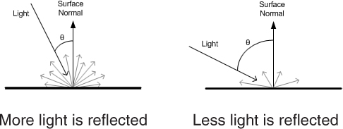
The scattering is uniform and does not depend on the viewing angle of the Camera. However, the angle between the light and the surface does affect the intensity of the reflected light, as shown in Figure 16.38. When the ray strikes the surface directly, it is reflected at maximum intensity. The reflection diminishes as the angle between the light and surface decreases. This is what causes the parts of the teapot facing the light to be illuminated while the parts facing away from the light source remain unlit.
Figure 16.38 Intensity of reflected light.
The color reflected by the Material is controlled by the Material’s Brush property. The image of the red teapot in Figure 16.37 was created by shining a white light on a DiffuseMaterial that reflects only red light:
![]()
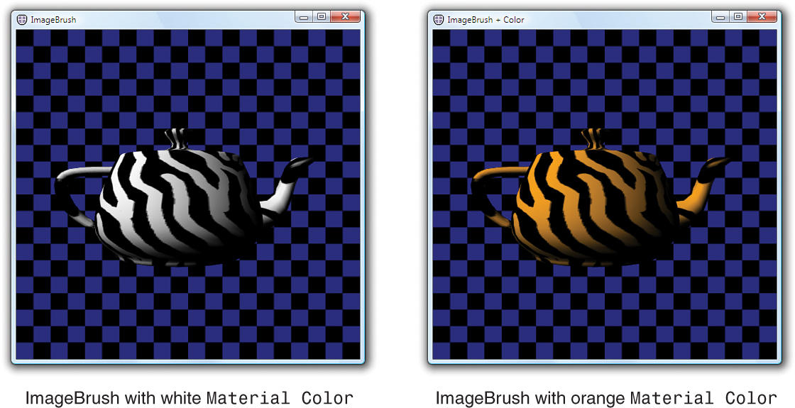
You can vary which colors are reflected by the Material over the object’s surface by using one of the nonsolid color Brushes. For example, the left side of Figure 16.39 shows the same teapot with zebra stripes applied by an ImageBrush:
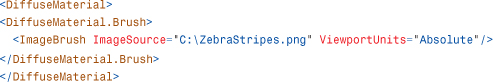
Figure 16.39 ImageBrush and the ImageBrush tinted orange.
Which part of the Brush appears on which part of the 3D surface is controlled by the texture coordinates (sometimes called UV coordinates) of the Geometry. Texture coordinates are discussed in more detail in the upcoming “TextureCoordinates” section.
Warning: If you’re not using a SolidColorBrush, you need TextureCoordinates!
If you attempt to use a GradientBrush, ImageBrush, DrawingBrush, or VisualBrush without specifying texture coordinates, your model will not render. Without texture coordinates, there is no mapping between points on the surface to the colors in the Brush. This is not a problem for SolidColorBrushes because all points on the surface map to the same color.
Missing or bad texture coordinates are usually easy to diagnose. If switching your Material to use a SolidColorBrush causes the model to appear, the odds are good that your geometry is missing texture coordinates.
Tip
By allowing you to use Brushes rather than static images as your texture source, texture mapping is made far more expressive in WPF. Not only can the 3D models themselves be data bound and animated, so can the content of their Brushes, which might be animated 2D Drawings, video, or even 2D Controls such as a DocumentViewer!
The right side of Figure 16.39 shows the same ImageBrush tinted orange, to look like tiger stripes. There are three ways this effect could be achieved:
• Modify the image used by the ImageBrush.
• Change the Color of the Lights in the scene to orange. White regions of a DiffuseMaterial reflect any color of light. If only orange light exists in the scene, orange light is reflected.
• Change the Color property on the Material to orange. Effectively, this is equivalent to changing the Light Color to orange except that it affects only this specific Material instead of all the Materials in the scene.
Typically, you will want to use the Color property on the Lights to vary the light intensity in the scene. You might also want to tint the Lights to match the ambient light of the environment—for example, green Lights for a scene in the forest, blue for underwater, and so on.
The Color property on Materials is useful when you want to filter the light that is reflected by specific objects. You might use this to tweak the lighting in a scene by darkening specific objects. Another use for this property is to get extra mileage out of an ImageSource by tinting it, as in Figure 16.39 to create tiger stripes from the zebra texture:
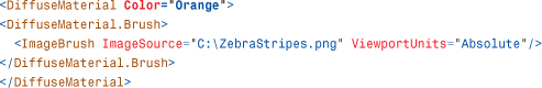
This technique can be especially helpful if you want the user to be able to choose a custom color for a 3D model, such as selecting the paint job for a car.
Digging Deeper: Calculating the Final Reflected Color
The final color that is reflected to the user is given by the formula
![]()
where Lc is the Color property of each Light, Mc is the Color property of the Material, and Mb is the color sampled from the Material’s Brush. The alpha components of the Material’s Color property and the color sampled from the Brush are multiplied together. The alpha component of the Light is ignored.
FAQ
![]() Why can’t you always see through translucent
Why can’t you always see through translucent DiffuseMaterials?
There are a number of ways to create a translucent DiffuseMaterial, including using an ImageSource with alpha, using the Brush.Opacity property, or using Alpha in the DiffuseMaterial.Color. If you create a translucent DiffuseMaterial, you might be surprised to find that objects behind it are sometimes not rendered.
This behavior is the result of how WPF handles overlapping surfaces. Rather than sort all the triangles in the scene and render them back-to-front, WPF uses a depth buffer to ensure that the surface nearest the Camera is rendered last (that is, on top). Using depth buffers is much faster than sorting the scene (and potentially subdividing interpenetrating geometry), but it has the side effect that once a surface near the Camera is rendered, surfaces further away are skipped. This is bad news if the nearer surface is intended to be translucent.
In order to ensure that translucent DiffuseMaterials render as intended, you need to take care when constructing a scene. Just as in 2D, objects in a 3D scene are rendered in the order in which they appear in the Children property. By placing translucent objects at the end of the Children collection, you can ensure that the objects behind the translucent objects are rendered first.
Another possibility is to create a translucent-like effect using EmissiveMaterials. EmissiveMaterials are blended additively and therefore do not use the depth buffer. EmissiveMaterials are discussed in the next section.
FAQ
![]() Where is WPF’s
Where is WPF’s AmbientMaterial class?
People porting code or importing file formats that are based on the fixed-function lighting from Direct3D or other 3D platforms might wonder why there is no AmbientMaterial class in WPF. Traditional fixed-function lighting allows the user to specify four material colors—ambient, diffuse, emissive, and specular—which are used to calculate the lighting contributions at the vertices.
Ambient and diffuse are similar but are specified separately so that users can limit the contributions of the omnipresent AmbientLight to portions of a scene. For example, you might have an outdoor scene that you want to brighten with an AmbientLight, but you do not want AmbientLight inside the entrance to a cave in a hillside. You would set the ambient color of the Material inside the cave to black to prevent AmbientLights from having an effect.
WPF exposes an AmbientColor property on DiffuseMaterial for this purpose. The normal Color property controls how the DiffuseMaterials reflect light from all Light types in the scene except AmbientLight. The AmbientColor limits the color of the light reflected from AmbientLights only.
Therefore, the diffuse, specular, and emissive materials colors in the traditional pipeline map to the Color properties of DiffuseMaterial, SpecularMaterial, and EmissiveMaterial, respectively. The ambient color maps to the AmbientColor property on DiffuseMaterial.
EmissiveMaterial
EmissiveMaterials always emit light visible to the Camera. They do not, however, emit light to other surfaces in the scene the way a Light does. The left side of Figure 16.40 shows the effect of the following EmissiveMaterial on the teapot model:
![]()
Figure 16.40 EmissiveMaterial on a teapot model.

EmissiveMaterials are additively blended into the image. Additive blending adds light to the image but does not occlude light from objects behind the material. This is why the checkered background is visible through the teapot on the left side of Figure 16.40. The bright green regions come from overlapping geometry that you wouldn’t normally see. (This is the rim of the lid, plus the handle and spout extend a small amount into the body of the teapot.)
To prevent a model from being see-through, you can combine the EmissiveMaterial with a DiffuseMaterial, using a MaterialGroup:
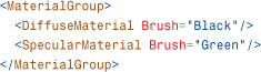
The right side of Figure 16.40 shows the result of this change.
In this case, the EmissiveMaterial is still additively blended with the image. However, by rendering a black teapot underneath, the end result is black plus the emissive color, resulting in just the emissive color. Also, note that you can no longer see the overlapping geometry inside the teapot. This is because the near side of the black teapot prevents you from seeing through to the overlapping lid, handle, and spout.
SpecularMaterial
SpecularMaterials reflect light back to the viewer when the Camera is close to the angle of reflection between the light and the surface. SpecularMaterial is also additively blended and by itself looks glasslike, as demonstrated by the following one shown on the left side of Figure 16.41:
![]()
Figure 16.41 SpecularMaterial on a teapot model.

Often, a SpecularMaterial is combined with a DiffuseMaterial to add a bright highlight characteristic of hard, shiny surfaces, as follows (shown on the right side of Figure 16.41):

Compare this with the image of the red DiffuseMaterial alone in Figure 16.37.
The “hardness” of the highlight is controlled by the SpecularPower property. The larger the value for this property, the more focused the specular highlight.
Tip
To make plastic-looking surfaces, you can combine a bright DiffuseMaterial with a white SpecularMaterial. To create metal-looking surfaces, you can use a dark DiffuseMaterial with a bright SpecularMaterial of the same hue.
Unlike DiffuseMaterial, which scatters light uniformly, SpecularMaterial reflects light in the opposite direction of the incident ray. As shown in Figure 16.42, the reflected light bounces off a SpecularMaterial like a mirror and is visible only when the Camera is close to the reflected ray.
Figure 16.42 Light bounces off a SpecularMaterial.

Note that because AmbientLights are directionless, they have no effect on SpecularMaterials.
As with the DiffuseMaterial, the final color reflected to the viewer is a combination of the Color properties of the Lights in the scene, the Brush of the SpecularMaterial, and the Material’s Color property. See the “DiffuseMaterial” section for more details on how the final color is computed.
Tip
Unlike traditional fixed-function lighting, which only allows you to specify a color for the specular highlight, WPF allows you to use any Brush. Using alpha in the image, you can create a Material in which specularity varies over the surface. This technique, called gloss mapping, can be used to add shininess only to the metallic parts of a texture for a car, fingerprints on glass, and so on.
Combining Materials
As you’ve seen in previous examples, MaterialGroup enables you to apply multiple materials to a surface. Materials in a MaterialGroup are rendered on top of each other in the order specified. Common uses include applying an EmissiveMaterial or SpecularMaterial over a DiffuseMaterial, as was done to create the Materials for the teapot in this section.
Geometry3D
Similar to the 2D Geometry class, Geometry3Ds are used to define the shape of 3D objects. By themselves, Geometry3Ds have no appearance. Geometry3Ds are combined with Materials using a GeometryModel3D to create a Model3D that can be rendered. There is only one concrete Geometry3D class: MeshGeometry3D.
A MeshGeometry3D represents a set of 3D surfaces specified as a list of triangles. MeshGeometry3D is composed of the following properties:
• Positions—Defines the vertices of the triangles contained in the mesh.
• TriangleIndices—Describes the connections between the vertices to form triangles. If TriangleIndices is not specified, it is implied that the positions should be connected in the order they appear: 0 1 2, then 3 4 5, and so on.
• Normals—Allows you to optionally tweak the lighting of the mesh.
• TextureCoordinates—Provides a 3D-to-2D mapping for each position used by the Materials.
Each of the Positions, Normals, and TextureCoordinates properties is a collection with one entry for each vertex in the mesh. For example, the position for the 0th vertex comes from the 0th entry in the Positions collection, the normal for the 0th vertex comes from the 0th entry in the Normals collection, and so on.
Positions
The triangles in the mesh are defined by specifying the 3D coordinates of their vertices. The coordinates are stored in the Positions collection of the MeshGeometry3D. By default, each group of three Point3Ds in the Positions collection is drawn as a triangle. The following snippet produces the triangle illustrated in Figure 16.43.
![]()
Figure 16.43 A triangle described by a MeshGeometry3D.

You can create a square by adding a second triangle, shown in Figure 16.44.
![]()
Figure 16.44 A square described by a MeshGeometry3D.
Front Sides Versus Back Sides
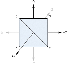
One of the things about 3D geometry that often surprises 2D developers is that the triangles in a MeshGeometry3D have separate front and back sides. Each side can be rendered using a different material. You also might choose to not render a side by leaving the Material property null. Which side of a triangle is the front is determined by the winding of the vertices. Figure 16.45 illustrates the winding of the triangles in the square, as viewed from the front and back.
Figure 16.45 Viewing the square from two different perspectives.

The winding is determined by the order in which the points are connected in the triangle. For example, connecting point 0 to point 1 creates a directed edge starting at 0 and ending at 1. The direction of the edges wind in a counterclockwise direction when viewed from the front, shown on the left of Figure 16.45.
Digging Deeper: Winding Order and Handedness
The section about Cameras introduced a right-hand rule to remember which direction the z-axis points in a right-handed coordinate system. There is a second right-hand rule that tells you which side of a triangle is the front. The direction your fingers curl when looking at your thumb indicates the winding direction. As illustrated in Figure 16.46, this is counterclockwise for a right-handed system.
Figure 16.46 The other right-hand rule.
The right-hand rule is also useful for remembering the positive direction of rotation in a right-handed coordinate system.
Tip
If you suspect that you have an issue with the winding in a mesh, you can set both the Material and BackMaterial properties so that the triangle will be visible, regardless of which side you view it from.
If it is acceptable to have the same material on both the front and back, you can ignore the issue of winding. However, it is sometimes useful to be able to specify different Materials for the front and the back. It is also faster to avoid rendering the BackMaterial if it will not be visible in the scene.
TriangleIndices
A mesh is built into the desired shape by adding triangles. Even curved surfaces are approximated by lots of little triangles. As the number of triangles in a mesh increases, so does the number of shared edges.
TriangleIndices enables you to share positions between triangles. When the TriangleIndices collection is empty, it is implied that the points should be connected in the order in which they appear in the Positions collection. When TriangleIndices exist, the points are connected in groups of three, as specified by the TriangleIndices. For example, you can create a square using only four unique points, as illustrated in Figure 16.47:
![]()
Figure 16.47 Indices of the vertices.
Sharing the position between triangles has a slightly different semantic meaning than declaring the same point multiple times. When the position is shared, the triangles are considered to be part of a single continuous surface. When the positions are separate, the triangles are separate abutting surfaces that can have different normals or texture coordinates.
Tip
Regardless of whether you use TriangleIndices, you do not need to worry about cracks appearing between triangles within a single MeshGeometry3D. WPF has strict rendering rules which guarantee that triangles sharing points are rendered as adjacent, without a seam.
However, you do need to be aware that transforms are not always exact. If you are using different transforms on two MeshGeometry3Ds to make them adjacent, it is possible that floating-point error in the transformations might create small gaps between the meshes.
Sometimes, you can work around this error by fudging the transform to create a small amount of overlap. Other times, you need to construct the MeshGeometry3Ds with points that are adjacent rather than transform them to be so.
Normals
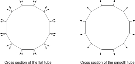
A normal is a vector that is perpendicular to a surface at a point. You specify normals at vertices to tell the system whether triangles represent flat surfaces or are approximating curved surfaces. Figure 16.48 shows the difference between flat and smooth shading on a tube approximated using 12 quadrilaterals.
Figure 16.48 Two tubes approximated using 12 quadrilaterals.

Tip
If you do not specify normals, the system generates them for you by averaging the face normals of each triangle that shares each vertex. If vertices are not shared between triangles, the result is the face normals, which gives the flat shaded appearance shown on the left side of Figure 16.48. If the vertices are shaded between adjacent triangles using TriangleIndices, the averaging results in the smooth shaded appearance shown on the right side of Figure 16.48.
When the normals for each vertex in a triangle are parallel, as illustrated in the cross section of the tube on the left side of Figure 16.49, the rendered surface appears flat. If the normals point in different directions, the shading is smoothly interpolated across the face of the triangle. To create a smooth surface like that illustrated on the right side of Figure 16.49, the normals of the adjacent triangles should be the same to prevent a crease from appearing.
Figure 16.49 Cross sections of the tubes from Figure 16.48.
Let’s consider the simple square mesh you have been building. If you want the square to appear flat, you specify all the normals perpendicular to the surface, as illustrated on the left side of Figure 16.50:
![]()
Figure 16.50 The result of using two different Normals values.

If you want the square to be lit as if it were an approximation of a slightly curved surface, you specify the normals to match the curvature of the surface, as illustrated on the right side of Figure 16.50:
![]()
TextureCoordinates
When you set the Fill property on a 2D Shape, it is assumed that you want the Brush to map to the 2D bounds of the Shape. In 3D, you need to provide this mapping yourself. Each entry in the TextureCoordinates collection is a 2D point in Brush space. These points map triangles in 3D space to triangles in Brush space. The triangles in Brush space provide the colors for the materials when the surface is rendered. Figure 16.51 illustrates how you would map the vertices in your square to stretch an image across it:
![]()
Figure 16.51 Mapping between 2D Brush space and 3D surface.
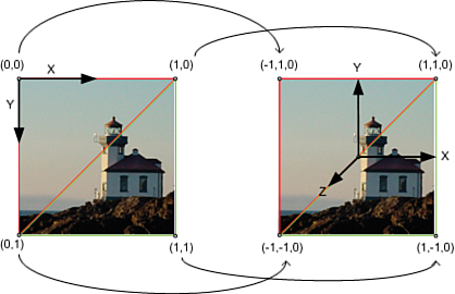
Keep in mind that in the 2D coordinate system that WPF uses, the origin is at the top-left corner, and the positive y-axis extends downward. By convention, the source image is usually considered to extend from 0 to 1 in both the X and Y directions.
Warning: By default, WPF texture coordinates are interpreted differently than you might expect!
You should be aware of a couple quirks with the way WPF handles texture coordinates. The default behavior of WPF texture coordinates closely matches the default behavior of 2D geometry, which is very convenient for 2D/3D integration scenarios. However, when you are attempting to use a mesh containing texture coordinates generated for a different system, there are a few Brush settings you will want to change.
The first is that, by default, Brush space is mapped to the bounds of the texture coordinates. This means that the following does not show the top-left quarter of the Brush as you might expect it to:
![]()
Instead, the bounds (0,0) – (0.5,0.5) become the relative bounds of the source, and the entire Brush is displayed. To prevent this, you set the ViewportUnits of the Brush to Absolute:
![]()
You will almost always want to do this when applying Brushes to 3D meshes. The default behavior is useful in 2D to map Brush space to the bounds of the 2D geometry being filled. In 3D, it is rarely used.
The second issue to be aware of is that some systems specify their y-axis as pointing upward in 2D instead of downward, as in WPF. If you are using texture coordinates generated for such a system, your Brushes will be applied upside down. You can correct for this with a simple Brush transform:
![]()
Finally, if your mesh has texture coordinates that extend outside the 0-to-1 range, it is likely that the intent was to tile. TileMode needs to be turned on explicitly in WPF:
![]()
ImageBrush is shown as an example, but these tips apply to all Brushes that use TextureCoordinates.
Model3DGroup
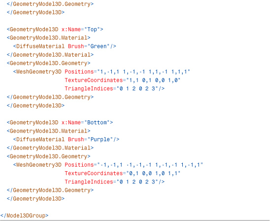
Model3DGroup derives from Model3D. Model3DGroups are used to group together a collection of Model3Ds into a single model. Grouping multiple GeometryModel3Ds together with a Model3DGroup is a way to build a model that uses multiple materials. Listing 16.4 shows how six GeometryModel3Ds can be combined to form a model of a cube. An alternative approach would be to create one MeshGeometry3D that uses a MaterialGroup to achieve the same effect.
Tip
Some 3D systems have an object called a “mesh,” which contains not only geometry information but materials as well. Sometimes, even multiple materials are permitted in a mesh. In WPF, this corresponds to a Model3DGroup containing multiple GeometryModel3Ds, one for each Material.


Visual3D
All elements that draw 2D content to the screen inherit their ability to render from the Visual base class. Similarly, Visual3Ds are nodes in the visual tree that can display 3D content. The Visual services—hit testing, bounding, and so on—extend to Visual3Ds as well and are accessible via the VisualTreeHelper class.
WPF provides three direct subclasses of Visual3D: ModelVisual3D, UIElement3D, and Viewport2DVisual3D. This section examines each one.
ModelVisual3D
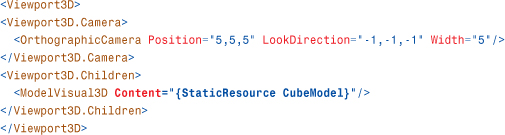
ModelVisual3D is similar to the 2D DrawingVisual and has been a part of WPF since its first version. To set the content of a ModelVisual3D, you use the Content property:
ModelVisual3D also has a Children property. Therefore, you use ModelVisual3Ds to compose multiple models into a scene inside your Viewport3D:
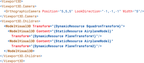
Children (and not Content!) is designated as ModelVisual3D's content property, so the preceding XAML adds the two children directly to the parent element. Keep in mind that Model3Ds can be reused between ModelVisual3Ds.
FAQ
![]() When should I use
When should I use Model3DGroup versus ModelVisual3D?
Although you can put together an entire scene by using a Model3DGroup displayed under a single ModelVisual3D (or ModelUIElement3D, covered later), you will be missing out on some important performance optimizations if you do this. ModelVisual3D (and ModelUIElement3D) are optimized to be scene nodes. They cache bounds and other information that lightweight Model3DGroups do not.
Going to the other extreme, you could use ModelVisual3Ds for each and every GeometryModel3D in a scene. Doing so is inadvisable because it unnecessarily increases the working set of the application. Model3DGroups are lightweight constructs intended for grouping multiple GeometryModel3Ds into a single model.
In general, you should use Model3DGroups to combine the various pieces of a single model (for example, the tires, windshield, and body of a car). ModelVisual3Ds (or ModelUIElement3Ds) should be used for displaying instances of 3D models (for example, use a ModelVisual3D for each car you add to the scene).
UIElement3D
Introduced in WPF 3.5, the abstract UIElement3D class and its subclasses take a step beyond the Visual3D class in bringing 2D framework principles to the world of WPF 3D. As mentioned earlier in this chapter, WPF’s 2D UIElements are often said to have LIFE (layout, input, focus, and eventing) support. Although there is no 3D layout, UIElement3D does have IFE (input, focus, and eventing). This dramatically simplifies tasks such as attaching mouse event handlers to 3D elements of a scene. Rather than being forced to process every mouse click event on your Viewport3D and then tease out exactly which of your 3D models was hit, you can simply add the event handlers directly to your individual UIElement3Ds.
There are two UIElement3D-derived classes in WPF: ModelUIElement3D and ContainerUIElement3D. If you remember the FooBar trick from the preceding chapter, then it shouldn’t be a surprise that ModelUIElement3D is a UIElement3D that contains a Model. ContainerUIElement3D is a UIElement3D that acts like a container.
ModelUIElement3D
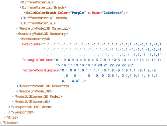
Listings 16.5 and 16.6 leverage ModelUIElement3D to create a clickable cube that changes color with each click. ModelUIElement3D has its own Model3D but no children. Notice that the MouseDown event handler is on the ModelUIElement3D and not on the Viewport3D.
Listing 16.5 MainWindow.xaml—A Clickable Cube

Listing 16.6 MainWindow.xaml.cs—Code-Behind for the Clickable Cube

ContainerUIElement3D
ContainerUIElement3D is a simple container for holding one or more ModelUIElement3Ds:

The ContainerUIElement3D class itself does not have its own Model3D, just a Children collection of type Visual3DCollection as its content property. ModelUIElement3DGroup might have been a more appropriate name for this simple class.
Note the difference between ModelVisual3D and the two UIElement3D subclasses. ModelVisual3D has both a Model3D as well as a Visual3DCollection. The UIElement3D classes separate this container and model functionality into the ContainerUIElement3D and ModelUIElement3D classes, respectively.
Viewport2DVisual3D
Introduced in WPF 3.5, the Viewport2DVisual3D class allows live interactive 2D content to be directly mapped to a 3D surface. Previously it was possible to map live 2D content onto 3D surfaces with VisualBrushes and DrawingBrushes. However, because they were just Brushes, they did not allow for interactivity. A Button drawn on a 3D sphere using a VisualBrush could never actually be clicked. Viewport2DVisual3Ds overcome this interactivity barrier: A Button mapped onto a 3D sphere actually responds to mouse clicks in 3D. A TextBox drawn on the face of a cube can be edited with the mouse and keyboard, just as you would expect. Multi-touch can be used to manipulate 2D elements mapped into 3D space. Even context menus for features such as spelling correction on a TextBox work!
The name Viewport2DVisual3D sounds odd, but it basically follows WPF’s naming convention. It is a Visual3D that acts like a 2D viewport. One confusing aspect of this name is that there is no Viewport2D class in WPF.
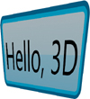
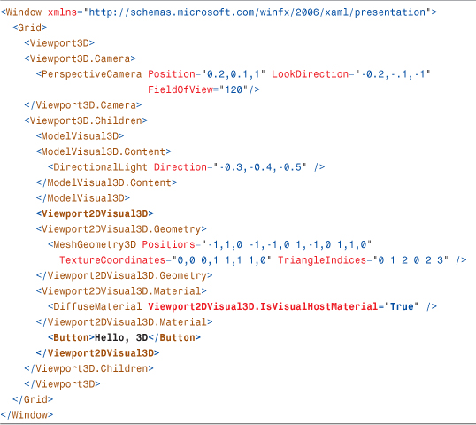
Listing 16.7 demonstrates how Viewport2DVisual3D is used with a simple Button. You provide the Viewport2DVisual3D with a MeshGeometry3D, a Material, and a target Visual. The interactive Material needs the Viewport2DVisual3D.IsVisualHostMaterial attached property set to true. If a Brush is associated with the interactive Material, it is ignored. The color associated with the host material is modulated with the target Visual’s color as usual. Figure 16.52 shows the result.
Figure 16.52 An interactive 2D Button mapped into 3D space.
Listing 16.7 An Interactive Button in 3D
Tip
Viewport2DVisual3D supports cached composition. It has a CacheMode property that works the same way as the CacheMode property on UIElement.
3D Hit Testing
As mentioned earlier, the simplest way to perform a hit test against a specific 3D model is to create a ModelUIElement3D and to give that ModelUIElement3D its own MouseDown event handler. But ModelUIElement3Ds are not a requirement for performing hit testing against 3D models.
Like their 2D Visual counterparts, Visual3Ds participate in visual hit testing. To perform a hit test against a Visual3D, you must first receive a hit test event on some 2D UIElement that contains a 3D scene, such as the parent Viewport3D element:
![]()
When the event handler is called, you can issue a visual hit test at that point:
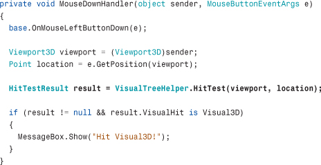
Of course, the overload of VisualTreeHelper.HitTest shown in Chapter 15, which uses callback delegates to report multiple results, also works with Visual3Ds. As in 2D, the results are returned in front-to-back order. To start a hit test from within the 3D scene, you can use the overload of VisualTreeHelper.HitTest that takes a Visual3D and a HitTestParameters3D.
Viewport3D
Viewport3D provides the opposite functionality of Viewport2DVisual3D. Whereas Viewport2DVisual3D is a Visual3D that enables 2D elements to be embedded inside 3D, Viewport3D is the 2D FrameworkElement that enables 3D elements to be embedded inside 2D.
The parent of a Viewport3D is always a 2D element such as a Window or Grid. The children of the Viewport3D are Visual3Ds. The 3D scene described by the Visual3D children is rendered inside the rectangular layout bounds of the Viewport3D. The Camera property on the Viewport3D controls the view of the 3D scene you see inside the Viewport3D.
Tip
Many container-like elements are normally sized during the layout system’s measure pass (described in Chapter 21, “Layout with Custom Panels”) to fit their contents. For example, a Button is typically sized to accommodate the text or other content inside it. Viewport3Ds work the other way around: Viewport3Ds adjust the view of the 3D scene to fit whatever its layout bounds turn out to be. By default, Viewport3D’s ClipToBounds property is set to false, meaning that its 3D content can actually exceed the layout bounds of the Viewport3D. If you’d like the Viewport3D’s content to stay within the rectangular region of the layout bounds, you set Viewport3D.ClipToBounds to true.
For this reason, you need to set the Width and Height properties of Viewport3D elements unless it is already being stretched to fit an area by layout. If you forget to do this, the Viewport3D defaults to a size of 0 by 0, and the 3D scene does not appear.
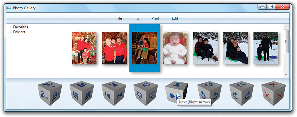
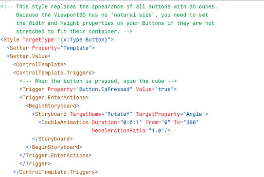
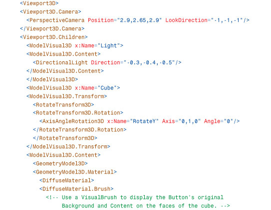
One of the neat things about a Viewport3D being a fully featured FrameworkElement that participates in layout is that you can easily integrate 3D elements into an application almost anywhere. In fact, it is possible for designers to use features such as Styles and ControlTemplates to replace the default appearance of controls with interactive 3D content. Figure 16.53 shows the result of applying such a style to the Photo Gallery example introduced in Chapter 7, “Structuring and Deploying an Application.” Note that the content and background that appear in the cube faces are data-bound to the templated Button. You can update the content and background, and the cubes update in real-time! When you click on the Button, the cube spins.
Figure 16.53 The cube Button Style applied to Photo Gallery.
Listing 16.8 The Cube Button Style

2D and 3D Coordinate System Transformation
WPF provides a number of services for transforming 3D points into 2D space and vice versa. This can be invaluable when applications require interaction between 2D and 3D content. For example, imagine writing a 3D molecule viewer with 2D text labels for the various atoms comprising the molecule. You’d like the text labels to be drawn as a layer on top of the 3D content, but you want the text to follow the atoms as the model is rotated. With these coordinate space transformation services, you can achieve this. Let’s take a look at the 3D transformation APIs provided and how to use them.
Visual.TransformToAncestor
Visual has a TransformToAncestor method that returns a GeneralTransform2DTo3D. This is useful when a Visual is hosted by a Viewport2DVisual3D. The returned object converts the hosted Visual’s 2D coordinate space into the 3D coordinate space of the Visual3D.
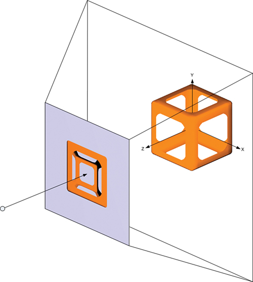
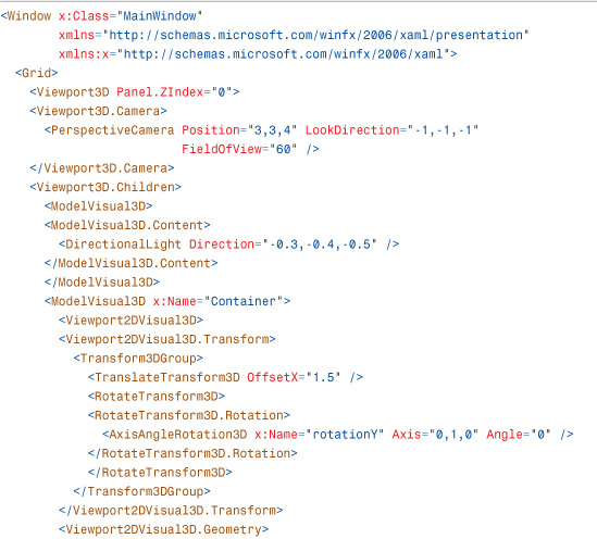
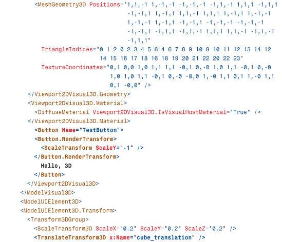
In Listings 16.9 and 16.10, the Point (0,0) from the Viewport2DVisual3D’s hosted Button is mapped into 3D space, and a purple cube is drawn where that Point3D lies in 3D space. As the larger cube rotates, the smaller cube follows it because the GeneralTransform2DTo3D changes as the larger cube rotates. Figure 16.54 shows the result.
Figure 16.54 Mapping (0,0), the Viewport2DVisual3D’s origin, into 3D space.

Listing 16.9 MainWindow.xaml—The Cube of Buttons and the Small Purple Cube


Listing 16.10 MainWindow.xaml.cs—Code-Behind That Keeps the Small Purple Cube in the Correct Location
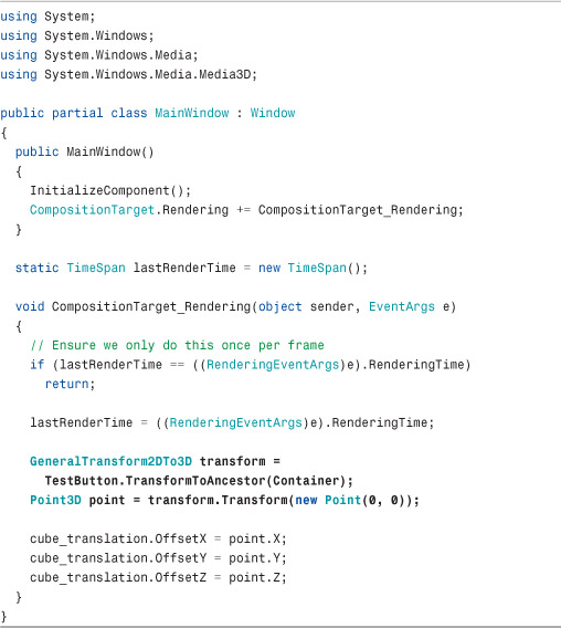
Listing 16.10 uses the CompositionTarget.Rendering event to perform the coordinate transformation once per frame. Be careful when using it, as structural changes in the scene can cause the event to be fired more than once within a given frame. This code ensures that the event handler logic runs only once per frame by leveraging the fact that the EventArgs instance is actually a RenderingEventArgs object that exposes a RenderingTime property.
Visual3D.TransformToAncestor and Visual3D.TransformToDescendant
Visual3D contains methods for the opposite scenario of mapping from 3D space into 2D space. The GeneralTransform3DTo2D returned by Visual3D.TransformToAncestor maps from the Visual3D’s 3D coordinate space into some 2D parent’s coordinate space. This is especially useful when an application tracks a 3D point on the screen and then draws 2D content whose position must follow that 3D point.
Listings 16.11 and 16.12 use TransformToAncestor to make the TextBlocks to follow the corners of the rotating cube, as shown in Figure 16.55.
Figure 16.55 Mapping the 3D points on the cube’s corners into 2D space.

Listing 16.11 MainWindow.xaml—The Cube and TextBlocks
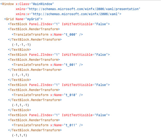


Listing 16.12 MainWindow.xaml.cs—Code-Behind That Updates the Locations of all TextBlocks
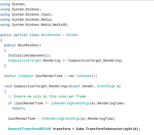

Every frame, the code gets the GeneralTransform3DTo2D between the cube and its parent Grid. It uses this GeneralTransform3DTo2D to transform all eight of the cube’s corner positions into screen space. The TextBlocks are then transformed in 2D space so that their positions match the transformed corners of the cube. As before, the transformation is done in the CompositionTarget.Rendering handler.
The remaining 3D transformation methods on Visual3D, TransformToDescendant, and another overload of TransformToAncestor simply provide GeneralTransform3Ds that will allow transformations between different Visual3Ds in a 3D object hierarchy.
Summary
You should now understand how the 3D APIs in WPF are a straightforward extension of the 2D APIs you are already familiar with. As shown in Table 16.1 at the beginning of this chapter, most of the 3D types are direct corollaries of the classes discussed in previous chapters. This makes WPF an ideal platform for applications that need to mix 3D graphics with a 2D user interface.
Although the 3D features of WPF might seem basic at a glance, hidden power comes from being a tightly integrated component of the platform. WPF 3D transforms can be data bound. You can display video, Drawings, or even 2D Controls on the surfaces of a 3D object. Entire 3D scenes can be used as DataTemplates and ControlTemplates. And all this works when printing, remoting, or running as a partial-trust web application.
This chapter focuses on the 3D-specific APIs, but it tells only part of the story. D3DImage, a powerful feature that enables interoperability with Direct3D, is covered in Chapter 19, “Interoperability with Non-WPF Technologies.” In addition, many of the best 3D features are general features of the platform. As you learn about animation and media in the upcoming chapters, keep in mind that these features can also be applied to 3D objects.