10
Electrochromic Display
Norihisa Kobayashi
Group on Advanced Imaging Materials and Systems (G‐AIMS), Graduate School of Engineering, Chiba University, JAPAN
10.1 Introduction
Electrochromic displays (ECDs) have been the subject of extensive research due to their excellent potential for application in novel paper‐like display devices, so‐called “e‐paper”. The EC device was first reported in the paper titled “A novel electrophotographic system” concerning to “display” in 1969, and anniversary 50 years have passed since then. Systematic and strategic research on EC materials and devices has increased since the 1980s. EC materials exhibiting clear color changes from colorless to the three primary colors (red, green, and blue, or cyan, magenta, and yellow) are required for full‐color e‐paper displaying devices. Recently, studies of electrochromism (EC) to realize full‐color reflective display with flexibility, bendability, and wearability are motivated by this concept and requirements. Papers reported are extensively increasing worldwide. This chapter is a brief review of electrochromic materials and displays toward full‐color reflective display and e‐paper. This chapter also includes the mechanism, characteristics, and recent progress of various EC materials and future applications in addition to display to clarify the advantages of ECDs.
Phenomena in which reversible color tone changes are induced by a stimulus are referred to as “chromism,” and have been long known. In recent years, “chromogenics,” defined as various reversible optical changes, including color, scattering, and reflection, has been recognized as a distinct technical field. Chromism includes a variety of phenomena that are named based on the relevant stimulus: “photochromism” induced by photon stimulus, “electrochromism” by electric energy, “thermochromism” by heat, “solvatochromism” by solvent, and so on. Widely known examples of photochromism include the photoisomerization of azobenzene, spiropyran, and diarylethene derivatives, the photochemical reaction of rhodopsin in retinal tissue, and sunglasses that change optical density in response to light intensity; photochromism is also expected to find application in ultrahigh‐density memory, photoresponsive devices and so on. Thermochromism is utilized in the well‐known card thermometer with a, a black background that employs a cholesteric liquid crystal and the erasable gel pen (Pilot Frixion BallTM™), which employs a thermosensitive reaction of leuco dyes and developer. Solvatochromism is widely utilized as a pH indicator. These examples demonstrate that many chromic phenomena are utilized in our everyday activities.
Although electrochromism (EC) refers strictly to a reversible optical change induced by electric energy described above, it is more generally defined as a reversible color change induced by an electrochemical redox reaction. This color change is based on a change in the electronic state caused by electron transfer between the material and an electrode. The EC phenomenon is similar to the discharge and charge of a secondary battery, and thus, EC is classified in a unique group different from electric field systems such as liquid crystal devices and electrophoresis. Tungsten oxide has been long recognized to exhibit color change, which has been known since the 1800s. Recently, many EC materials have emerged, such as inorganic, organic, and conducting polymer materials. These materials offer many advantages, including multi‐color, low operation voltage, memory effects, etc. With the development of these materials, EC was expected to be applied to an imaging device called an ECD from as early as the 1980s.
The ECD is a light‐receiving and reflective display. Unlike light‐emitting displays such as the transmissive liquid crystal display (LCD), organic light‐emitting diode (OLED), and the plasma display panel (PDP), the ECD offers high visibility under daylight conditions and a wide view angle and can reduce eye strain in the case of continuous use. Consequently, the ECD was expected to be applied to novel display systems. In fact, ECDs such as a 7‐segment clock and an information board for displaying stock prices were test‐marketed in the 1980s. However, the production of these items was discontinued because of the slow response time of the EC reaction, which occurs with the diffusion of substances (ions). Subsequently, LCD studied in the same period emerged for quick response displays such as TV and PC monitors.
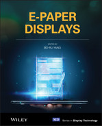
Because of these factors, EC was applied to devices that do not necessitate a quick response time. In recent years, the use of natural energy has extensively collected attention from the perspective of environmental concerns, and the application of EC to a passive solar system for controlling the transmission of and for utilizing solar energy became an active area of focus. The passive solar EC system was expected to be applied to “curtain‐less” smart windows, which control the amount of transmitted sunlight and increase air conditioning efficiency [1–3]. Smart windows have, in fact, already been put into practical use in Europe and the United States, as shown in Figure 10.1a. Another universal application of EC to automobile interior and exterior dimmable mirrors brought astonishing success in the EC field. The company also provided large‐scale automobile privacy dimmable panels with EC for energy‐conservation smart automobile systems, as shown in Figure 10.1b; these are already available on the market for motor vehicles. Figure 10.1c illustrates an aircraft light‐modulating window called “dimmable window,” installed in Boeing 787 Dreamliner as standard equipment, which is one of the most popular and eye‐catching applications.
Nevertheless, it is still expected that EC will be applied to information displays. The slow response of EC previously precluded the development of EC‐based information displays. However, in recent times, EC has re‐emerged as a strong candidate for paper‐like reflective displays, such as an e‐paper, requiring memory property without quick response. The demand for novel paper‐like information display media has re‐initiated the study of EC for such display uses.
10.2 Structure of Electrochromic Display
Generally, an EC device is constructed by sandwiching an electrolyte solution between electrodes, similar to a battery, as shown in Figure 10.2. At least one of the electrodes is transparent, allowing observation of the color change of the cell. EC materials are dissolved in the electrolyte solution or attached as modifications to the electrode surface as a coloration layer. Although solutions, inorganic solids, polymers, gels, and ionic liquids have been used as the electrolyte layer, high ion conductivity materials are desired, as with a battery.
The EC device is a two‐electrode cell composed of an anode and a cathode. The electrochemical reduction of a reducible material on one electrode should be accompanied by electrochemical oxidation of an oxidizable material on the other electrode with an equivalent amount of charge. Therefore, the EC device requires a counter material that compensates for the charge consumed on the counter electrode's coloration electrode. Since EC is a current‐driven system like OLED, energy‐saving ability is often debated compared to voltage‐driven electrophoretic and liquid crystal systems. Even in ECD, consumed energy increases with increasing the number of writing and erasing processes. However, the EC with sufficient memory properties does not require energy to retain the image (just like to keep charged state in a secondary battery), leading a possibility to show very low energy consumption rather than voltage‐driven system if the number of writing erasing is not so frequent. Therefore, consumed energy depends on the number of writing and erasing processes. EC (Coloration) efficiency is commonly used to measure energy consumption when its value is compared with other EC values. EC efficiency is defined as the change in optical absorption per injected charge amount (so‐called change in absorbance in coloration per injected charge density). Since charges required for writing in EC (mC/cm2) are about 1000 times larger than that of LCD (μC/cm2), the design of EC materials, counter materials, and device structure with and for high EC efficiency is considerably important to decrease energy consumption. The EC efficiency of EC devices is improved by employing suitable counter electrode systems that undergo electrochemical reactions that compensate for the charge consumed at the coloration electrode. If the counter material exhibits a color change associated with the electrochemical reaction, it may interfere with the color of the coloration electrode, and a white scattering/reflective layer must be introduced, especially in the case of a reflective display such as e‐paper.
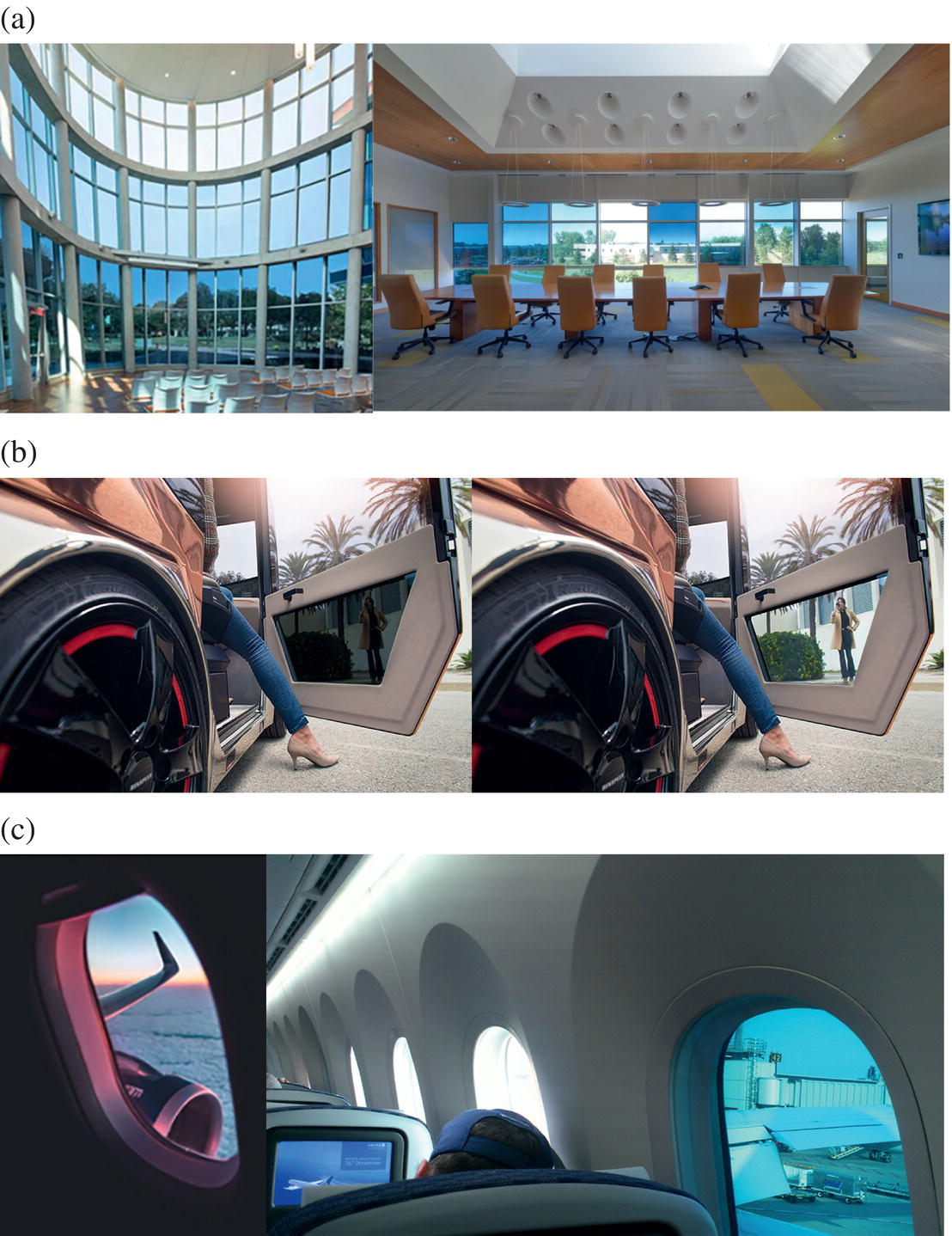
Figure 10.1 Electrochromic Applications: (a) smart windows, Source: Sageglass. (b) privacy dimmable panel Source: Rinspeed AG and (c) dimmable aircraft windows Jesse Echevarria/unsplash;Flickr/Payton Chung.
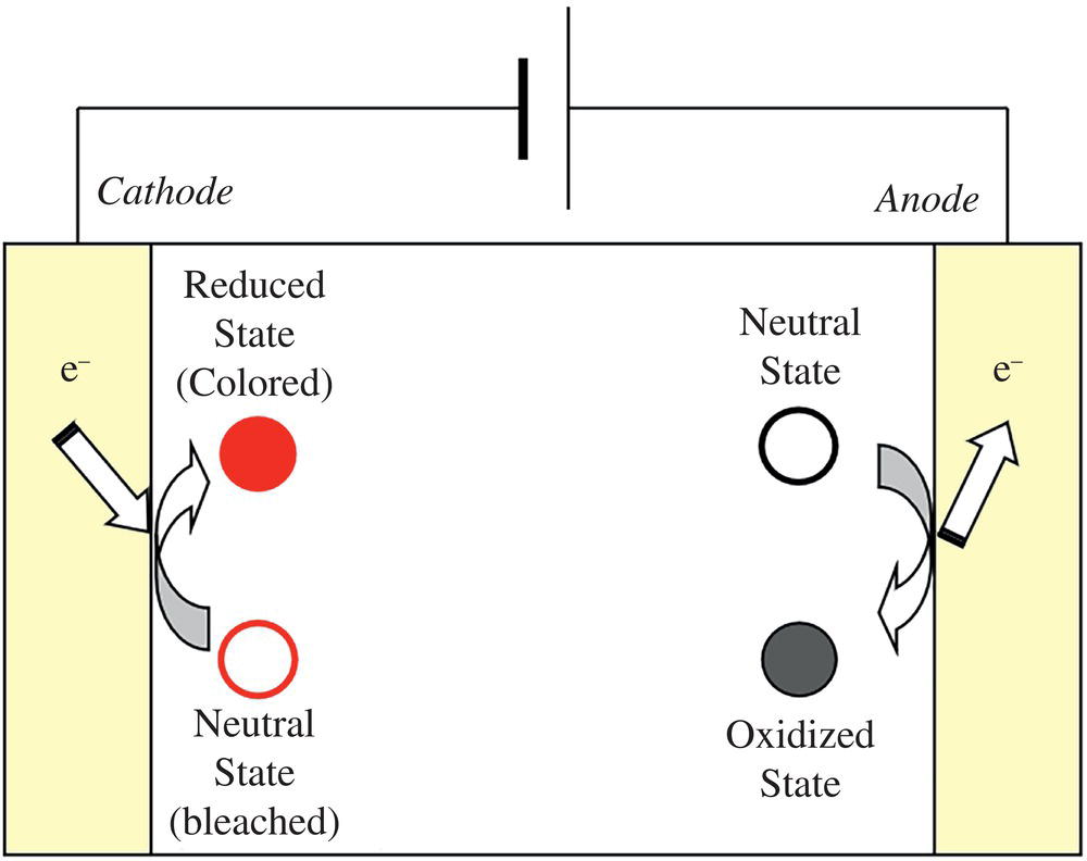
Figure 10.2 The typical structure and coloration mechanism of EC cell.
On the other hand, the counter electrode does not need to exhibit an electrochemical reaction for the charge compensation. For example, an electrochemical capacitor can accumulate the charge as a space charge by using an electric double layer. In fact, multiple colorations of anodic and cathodic EC was demonstrated in a single EC device with a hybrid capacitor architecture in which ITO nano‐particle or porous carbon modified electrode was used as counter electrode. In this device, even large charge amount consumed by multiple redox pairs' EC materials was adequately compensated [4, 5]. In this way, many kinds of counter electrode systems become available, and an effective combination of the coloration electrode system and the counter electrode system is important for improving the characteristics of the EC cell.
10.3 EC Materials
10.3.1 Inorganic EC Materials
One typical inorganic EC material is tungsten oxide (WO3) [6]. An EC cell employing WO3 thin film was reported by S.K. Deb et al. in 1969 [7]. The redox process of WO3 can be expressed in the following electrochemical reaction:
When the WO3 layer modified onto an electrode receives an electron from the electrode, a cation in the electrolyte is introduced into the WO3 layer for charge compensation, as shown in Figure 10.3. Specifically, the WO3 crystal has a perovskite structure comprised of W6+ and O2−. A certain amount of W6+ is converted to W5+ by electrochemical reduction. WO3 comprising the mixed‐valence states of W6+ and W5+ is strongly colored by an intervalence transfer band. Cations having a small ionic radius (H+, Li+, etc.) can be introduced into the crystal lattice of WO3 for charge compensation. Based on the film‐forming method employed, quick response times of less than 100 ms can be achieved in the WO3 film, along with long‐term switching stability exceeding 107 cycles.
Many other inorganic materials [8] such as Prussian blue (PB), NiO, Ir(OH)x, V2O5, and CeO2 are also known to exhibit EC. These inorganic materials have already been applied to optical shutters, anti‐glare mirrors, and smart windows based on their long‐term switching stability and absorption in the infrared region. Recently, studies on PB are gradually increased from a viewpoint of color display because PB is known to expend its color variation by changing central metal ions. However, in the case of e‐paper requiring low energy consumption and flexibility, inorganic materials may be disadvantageous. Depending on the film‐forming method and cell structure, the coloration efficiencies of inorganic materials are within the range of 20–100 cm2/C. EC efficiency is defined as the change in absorbance in coloration per injected charge density. These values are lower than those of organic EC materials and conducting polymers. Low energy consumption driving can be achieved by developing high EC efficiency inorganic EC materials and improving the cell structure.
![Schematic illustration of coloration mechanism of WO3 based EC material [7] / Optica Publishing Group / Public Domain.](https://imgdetail.ebookreading.net/2023/10/9781119745587/9781119745587__9781119745587__files__images__c10f003.jpg)
Figure 10.3 Schematic representation of coloration mechanism of WO3 based EC material [7]/ Optica Publishing Group / Public Domain.
One of the shortcomings in inorganic EC materials is color variation and multicolor presentation. A new strategy for color variation in inorganic EC comes true. Fabry‐Perot nanocavity structure was fabricated by stacking the WO3 EC layer and a partially reflective metal layer on the substrate as EC layer [9]. This structure enables strong interference resulting in various structural colors. The EC device with NiO counter electrode demonstrated vivid reflective color suitable for displaying. Multicolor representation, including transparent state, was reported using the intercalation of Zn2+ ion into the sodium ion stabilized vanadium oxide modified cathode [10]. Counter Zn electrode was located at the peripheral position of the device. Color switching between orange‐light green‐orange was demonstrated. Colorless transparent was not provided right now. These findings indicate that inorganic EC will be a potent candidate for full‐color display, including e‐paper.
10.3.2 Organic Electrochromic Materials
As previously described, inorganic EC materials, including metal oxide, are suitable for binary displays such as blue and transparent or white presentations. However, in the case of color displays, organic EC materials offer several advantages. Recently, increasing research efforts have been dedicated to the EC of organic compounds such as dyes, metal complexes, and conductive polymers from the viewpoint of multicolor and coloration efficiency. Examples of the application of organic EC materials to increase color palette leading to full‐color e‐paper, are emerging. Compared with inorganic oxide systems, organic EC materials offer color variety and EC efficiency advantages. Organic EC materials present various colors, including the three primary colors (such as red, green, and blue [RGB], or cyan, magenta, and yellow [CMY]) and colors intermediate between these. Organic EC systems, in which various colors may be derived from single materials and multicolor may be achieved by stacking the cells, are anticipated to be strong candidates for satisfying the rising demand for e‐paper, such as in the case of black and white, multicolor and full‐color representations.
Viologen derivatives, N,N′‐dialkylated di‐cations of 4,4′‐bipyridine, exhibit various colorations upon variation of the quaternization agent. The viologen derivatives and analogous molecules are known as EC materials [11]. These organic materials show high EC efficiency compared to inorganic EC materials. The di‐cationic derivatives of viologen can be dissolved in water and organic solvents depending on the molecular structure. The color change of viologen derivatives is induced by electrochemical reduction,. The reduced derivatives are deposited on the cathode due to the change in the solubility on turning from the di‐cationic state to the mono‐cationic state. However, like many other organic EC materials simply dissolved in an electrolyte solution, viologen derivatives do not exhibit quick response in common EC systems because the diffusion of the molecules and charge transfer between molecules is kinetically limited. In addition, viologen derivatives suffer from the disadvantage of bleaching because the colored states of the viologen derivatives sometimes crystallize and detach from the electrode as the colored precipitates.
To obviate the disadvantages of the viologen system, viologen derivatives were adsorbed onto the surface of titanium dioxide (TiO2) nanoparticles modified on the electrode [12]. TiO2 was prepared on the transparent electrode as a thin film of a few micrometers in thickness using the same method employed in the dye‐sensitized solar cell. This TiO2 thin film is porous, and its effective surface area is more than a thousand times the area of the geometrical electrode surface. Therefore, the viologen derivative adsorbed onto the TiO2 surface has a high surface concentration, as shown in Figure 10.4. An experimental EC device constructed with a viologen derivative adsorbed TiO2 nano‐particle electrode exhibited long‐term switching stability, more than several thousand times in −1.3 V driving. The charge transfer between TiO2 and viologen is more efficient than that of the unmodified transparent electrode system; thus, the viologen‐modified TiO2 nano‐particle system demonstrated quick response and high EC efficiency. In fact, the EC efficiency of the TiO2 nanoparticle system was about 20 times higher than that of the systems without the TiO2 nano‐particles layer. The viologen‐modified TiO2 nano‐particle system achieved a quick response time of several milliseconds due to the high mobility of charge compensation ions within the porous electrode the high electron transfer rate between viologen and TiO2. This system has been widely studied and applied to the almost successful development of e‐paper, such as an electronic book using the viologen system. For full‐fledged applications to e‐paper, prototype EC devices of the TiO2 nano‐particle system fabricated by the screen printing method were also reported. Thus, the TiO2 nano‐particle system has potential to further develop ECDs.
Recently, application to rollable and flexible subpixelated ECD was reported with viologens for wearable display. The TiO2 nano‐particle system shows pretty nice EC properties but is not good for stretchable and rollable application at present due to issues on stretchability and rollability of thermally connected inorganic TiO2 nano‐particles layer. As electrode, in addition to ITO on flexible PET substrate, single‐walled carbon nanotube/Pd‐coated Ag nanowire conducting bilayer on PDMS flexible substrate was also utilized for high chemical stability and excellent mechanical robustness against external strains. UV curable gels, including viologens, counter ferrocene derivative and the ionic liquid was pixelated through photomasks to fabricate subpixelated rollable ECD. Each subpixel was positioned side‐by‐side configuration just like color filters in an emissive display. The ECDs exhibit high durability even after 1000 cycles of mechanical bending tests at a bending radius of 10 mm [13, 14].
![Schematic illustration of viologen derivative-modified TiO2 nano-particles modified electrode Adapted From [12].](https://imgdetail.ebookreading.net/2023/10/9781119745587/9781119745587__9781119745587__files__images__c10f004.jpg)
Figure 10.4 Schematic representation of viologen derivative‐modified TiO2 nano‐particles modified electrode Adapted From [12].
Examples aiming for applying full‐color e‐paper have also been reported by the combination of three primary color EC. Since e‐paper should be a reflective display, the three primary colors, cyan, magenta, and yellow (CMY), are suitable for full‐color representation of e‐paper as in the case of photography and printing. On this basis, the electrochemical properties of phthalate derivatives were evaluated. The three primary colors (cyan, magenta, and yellow) were electrochemically obtained in the ITO sandwich cell using diacetyl benzene, dimethyl terephthalate, and biphenyl dicarboxylic acid diethyl ester, respectively, as shown in Figure 10.5. Each color obtained with the various derivatives is regarded as one of the three primary colors based on the CIE 1931 colorimetric measurement [15]. It was revealed that the anion radical of each derivative generated at the cathode exhibited each three primary colors (in case of dimethyl terephthalate; monomeric structure of polyethylene terephthalate PET, shows magenta color), and that the coloration was affected by the supporting electrolyte and solvent. Red, green, blue, and black have also been achieved by stacking two or three primary color EC cells [16]. Figure 10.6 displays a photograph of the three‐layered ECD. The color of this three‐layered ECD was based on the subtractive color mixing process. Blue, red, and green pixels were obtained by Y + C, M + C, and Y + C combinations, respectively. The black color of this three‐layered ECD was not adequate because the CMY subtractive color mixture process cannot fully represent a chromatic black. Therefore, a full‐color reflective display based on the present system requires four layers (cyan, magenta, yellow, and black), as is the case with color printing. It was anticipated based on the facts mentioned above that the phthalate derivative‐based EC cell should be a candidate for a multi‐ or full‐color e‐paper. Fabricating flexible EC cells has been demonstrated using an ITO coated flexible plastic electrode and a gel electrolyte. The flexible EC cell exhibited a clear color change, as is the case with the glass‐electrode EC cell.
For the practical application, the cycle stability of the phthalate derivative‐based sandwich EC cell is very important. In the case of a 2‐electrode sandwich cell, a counter material is necessary to improve the cycle stability of the EC cell. Several counter materials such as ferrocene, carbon, nickel oxide, and so on in the phthalate‐based EC cell were examined to improve cycle stability. Carbon is not electroactive but is effective in forming reversible electric double layer by ion adsorption and desorption on its surface. Therefore, it works as a capacitive layer to hold charges consumed at the working electrode. Particularly, nickel oxide was reported to work as an excellent counter material in phthalate‐based EC cells. Cycle stability over 5000 coloring and bleaching cycles were reported [17]. This clearly indicates that even organic phthalate derivatives are not so weak in an EC cell by adopting suitable counter material and charge compensation system.

Figure 10.5 Digital camera images of colored state of terephthalate derivatives‐based ECD. Colorimetry analysis of its colored states with CIE 1931 Yxy color diagram [15] / Royal Society of Chemistry.
![Schematic illustration of digital camera image of the three-layered ECD with an 8 by 8 pixels resolution and passive matrix drive [16] / with permission of Elsevier.](https://imgdetail.ebookreading.net/2023/10/9781119745587/9781119745587__9781119745587__files__images__c10f006.jpg)
Figure 10.6 Digital camera image of the three‐layered ECD with an 8 × 8 pixels resolution and passive matrix drive [16] / with permission of Elsevier.
The memory property is also an important factor for e‐paper applications to reduce energy consumption and realize continuous tone (grayscale) representation. If EC materials show excellent memory properties, it is easy to realize continuous tone because the EC material keeps a certain absorbance (coloration) without power supply, depending on the injected charges, as is the case with a variation of charging level in a secondary battery. However, the memory properties of phthalate derivatives are inefficient even in the open‐circuit state of the EC cell. Application of continuous DC voltage with different magnitude to the EC cell can realize continuous tone, but this results in the consumption of a large amount of energy and a possibility of decomposition of the EC materials and cell. Therefore, a phthalate‐based EC cell's continuous tone representation was realized by applying a suitable frequency rectangular wave voltage with various duty ratios instead of a DC voltage. According to a subtractive color mixture process, multiple colors, including intermediate colors between cyan, magenta, and yellow, were successfully demonstrated by stacking EC cells with a different tone (Figure 10.7) [18].
For full‐color e‐paper application of EC, innovative progress was made in 2011 [19]. Multi‐layered EC consisting of one display unit was developed, and TiO2 modified electrode system and three primary color organic dye‐based EC were combined to realize full‐color ECD. The white reflectivity was 70% at 550 nm, and multi‐layered ECD showed 27% of color reproducibility compared with the standard color chart. Active matrix multi‐layered ECD flexible panel using 3.5″ QVGA LTPS‐TFT successfully expressed full‐color image as shown in Figure 10.8. A possibility of flexible multi‐layered ECD was also pointed out. This strongly supports that EC can be a technology for the real full‐color e‐paper.
Very recently, a new paradigm was reported in the organic EC system. A combination of leuco dyes, including fluoran and developer, was well known as a stimuli‐induced colorant. This combination was commonly and widely utilized and commercialized in the thermochromic system, such as the erasable gel pen (Pilot Frixion Ball), thermal writable card, and so on, as previously mentioned. The developer works as a proton donor to stabilize the lactone ring‐opening state. In a common organic low‐molecule EC system, unstable radical is generated in either anodic or cathodic coloring molecules. This instability results in low cycling stability and less image retention, memory effect, properties. Certain leuco dyes themself have electrochemical activity and are easily oxidized. However, a structural change occurred after oxidation. Therefore, its reverse reaction to the neutral state required more negative potential. Cycling stability over several 10 times was not obtained. A new paradigm utilized the redox reaction of a developer to release proton, not to utilize the redox reaction of leuco dye. 2,3‐Dimethylhydroquinon/benzoquinone (DMHQ) redox couple was reported to work as a proton donor and acceptor [20]. Gel electrolyte containing leuco dye showing suitable color and DMHQ was sandwiched between ITO electrodes to fabricated ECDs. ECD showing colorless transparent (T) and black (B) was incorporated with an optical see‐through head‐mounted display to fabricate an augmented reality display (ARD). The B state of ECD works well to enhance the visibility of displayed images under strong ambient light conditions. Display composed of conventional RGB color filter and ECD showing colorless transparent (T) and black (B) with white (W) reflector was demonstrated. Further, a side‐by‐side placed RGB‐colorless EC color filter was stacked on the ECD showing T‐B with W reflector, and color coordinates and color gamut were evaluated in the CIE 1931 color space [21]. A more attractive redox developer, urea derivative, was proposed, and impressive EC properties were reported. Combination of electroactive urea derivative and pH‐sensitive rhodamine B derivative with closed ring structure gave excellent bistability (decay 7% in an hour), reversibility (over 104 cycles), coloration efficiency (430 cm2/C) and concise color‐switching time (2 ms), as shown in Figure 10.9 [22]. This combination showed nice light and thermal stability in‐ring open and close states. The mechanism was based on intermolecular proton‐coupled electron transfer (PCET) to increase proton concentration near dyes after oxidation leading to coloration. A prototype for a bistable electronic billboard and reader display device with high energy efficiency was demonstrated with this EC system. The same authors also designed and developed a superior bistable EC device with good overall performance, including bistability (>52 hours), reversibility (>12 000 cycles), coloration efficiency (≥1240 cm2/C), and transmittance change (70%) with fast switching (≤1.5 seconds) [23]. This superior mechanism was based on concerted intramolecular PCET, which was achieved in the designed polymer with fluoran and redox‐active proton donor unit. A prototype EC electronic shelf label was also successfully demonstrated. Taking variation of leco dyes, including fluoran structure and redox‐active proton donor and resulting in excellent overall performance into account, this system can accelerate EC to various application fields. This will raise up the value of EC as a new wave and will be a potent candidate for energy saving display such as e‐paper.

Figure 10.7 Color representation of stacked phthalate‐based EC cell, two of which with different tone are stacked together. The coloration area of the EC cells was 1.0 × 1.0 cm2 [18].
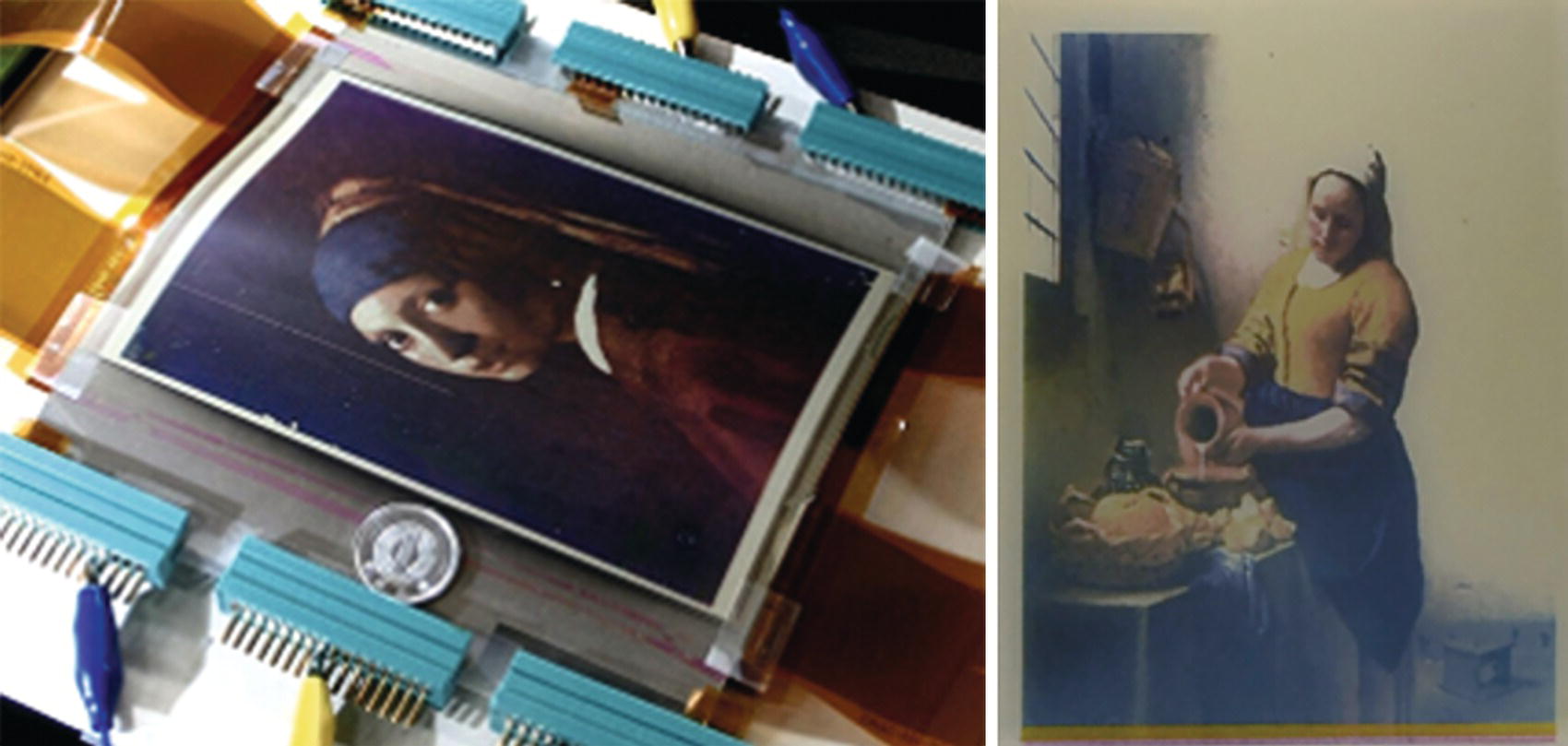
Figure 10.8 Demonstrated image of active matrix 3.5” QVGA LTPS‐TFT multi‐layered flexible ECD panel Tohru Yashiro / Ricoh Company, Ltd.;Mikolaj Niemczewski / Adobe Stock.
10.3.3 Conducting Polymers
Conducting polymers have been a focal prospect for film formation, multicolor property, and EC efficiency. The coloration efficiencies of the well‐known conducting polymers, polybi‐thiophene and poly(3‐methyl thiophene), are 100 and 240 cm2/C, respectively. The potential of poly(3,4‐alkylenedioxythiophene) molecules, typified by poly(3,4‐ethylene dioxythiophene) (PEDOT), and copolymers of the monomers of these molecules with other conjugate monomers have been recognized in conducting polymer systems in recent years. PEDOT possesses an ethylenedioxy group in positions 3 and 4 of the thiophene ring. Improved conductivity and redox switching stability have been achieved with PEDOT, derived from high electron density and reduced distortion of the thiophene ring due to the substitutional effect of the ethylenedioxy groups. Various colorations, including RGB, may be accessed using the copolymers of the alkylenedioxythiophene system by judicious variation of the combination of monomers [24]. Certain copolymers of this category exhibit coloration efficiencies higher than 1000 cm2/C [25]. In addition, conducting polymers exhibit quick response and good memory property and thus, may be advantageous for electric power saving. Recent remarkable progress in EC of conducting polymers such as color variation, quick response, and so on are reported by academic scientists [26–29].
On the other hand, the conductivity and narrow bandgap of conducting polymers are debated to realize the fully‐transparent state suitable for e‐paper and display. Generally, transparent polymers are insulating, and most conducting polymers show some color in certain of their neutral and redox states. Therefore, conducting polymers may be disadvantageous to realize clear full‐color representation.
For the application to stretchable, bendable, and wearable display, conducting polymer motivated EC researcher because of its processability and stability. Flexible and stretchable EC devices were demonstrated with PEDOT/PSS EC ink graphically printed on ITO/PET electrode using screen‐printing or inkjet printing. For a 5 × 5 cm display, the full transition takes approximately 2.5 seconds with a maximum 3 V application. The active operation temperature ranging from −100 °C to +100 °C was achieved, and the displays are bendable up to a 7.5 mm radius [30]. A stretchable array of active‐matrix (AM) ECD was fabricated by using poly(3‐methyl thiophene) (P3MT) and Prussian blue (PB) electrodes with gel electrolyte on a deformable substrate. The ECD exhibited red, green and blue (RGB) depending on the applied voltage but not colorless state, and low power consumption of and 378 μW/cm2 (10 seconds duration) and a high coloration efficiency of 201.6 cm2/C at 1.0 V application driving. A stretchable 6 × 6 a.m. ECD array for higher resolution display with patterned liquid metal GaInSn interconnection also shows mechanical stability under 30% biaxial stretching. These researches are targeting wearable display system. As thinking of environmental effects on both the processing and disposal of electronic devices become important rapidly, the ability to replace plastic and glass substrates with bioderived and biodegradable materials remains a major technological goal. According to this concept, a cellulose nanofiber‐coated paper substate was used to fabricate ECD (Figure 10.10) [31]. PEDOT/PSS works well as the electrode on the paper substrate in this device. This paper ECD exhibited 9000 cycles ON and OFF EC stability even higher surface resistance of 460 ohm/sq as an electrode. This is probably attributed to the advantage of conducting polymer ECD, such as high conductivity and low driving voltage. The authors claimed that the paper ECD was combusted in the air leaving 3% of the initial mass at 600 °C, highlighting this approach as a promising route toward disposable displays. In some meanings, these results well match a concept of e‐paper display.
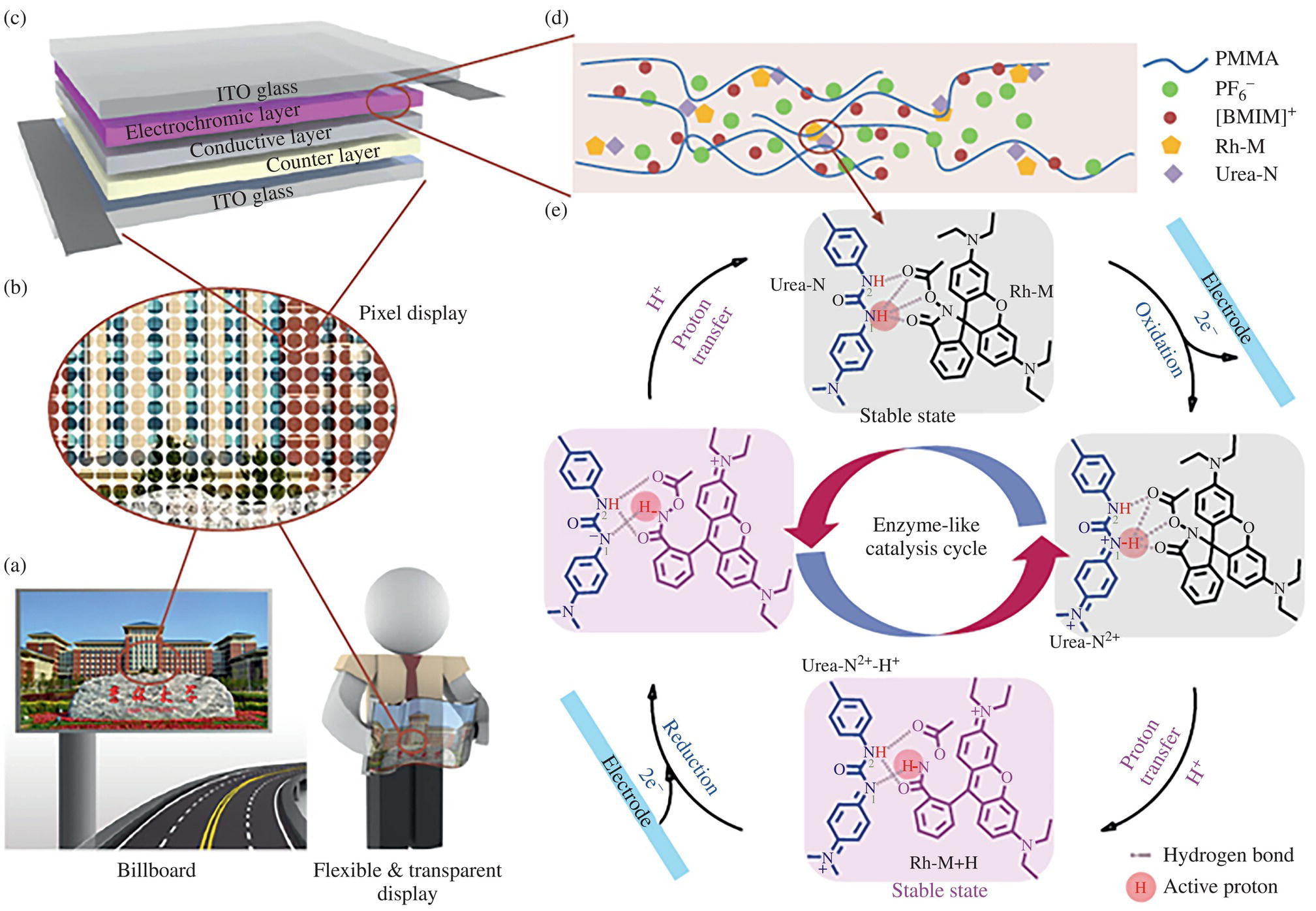
Figure 10.9 Schematic diagrams and mechanism of the “Urea‐N+Rh‐M” electrochromic system: Schematic of energy‐saving billboard (left) and flexible transparent display (right), (b) Schematic of pixel display, (c) Structure of bistable electrochromic device, (d) The composition of the electrochromic layer and (e) The proposed mechanism (gray dashed line: hydrogen bonding between Urea‐N and Rh‐M; red circle: active proton that transferred between Urea‐N and Rh‐M) [22] Zhang, W., et.al, 2019 / Springer Nature / CC BY 4.0.
![Schematic illustration of fabrication process for lateral paper-ECDs showing inkjet-printed PEDOT: PSS electrodes, deposition of ECPs, and [EMI][TFSI]/PVDF-HFP ion gel electrolyte layer.](https://imgdetail.ebookreading.net/2023/10/9781119745587/9781119745587__9781119745587__files__images__c10f010.jpg)
Figure 10.10 Fabrication process for lateral paper‐ECDs showing inkjet‐printed PEDOT: PSS electrodes, deposition of ECPs, and [EMI][TFSI]/PVDF‐HFP ion gel electrolyte layer. Devices are operated by applying a 0.8 V bias across the two lateral pixels [31] / John Wiley & Sons.
10.3.4 Electrodeposition (Electroplating)
Electrodeposition can be described as an aspect of EC. A well‐known electrodeposition process is the electroreduction of metal ions, commonly known as metal plating. The Zn electrodeposition system, in which electroreduction of Zn2+ is performed in solution, was reported in the 1920s. Subsequently, black and white presentation by electrodeposition of Bi was reported in 1995. The Bi electrodeposition system exhibits good contrast because colorless Bi3+ accentuates the white color of the white reflector. The EC efficiency for this Bi electrodeposition system is 75 cm2/C at 700 nm, with a high white and black contrast ratio of 25 : 1 because colorless Bi3+ ions don't dull the color of the white coating layer. It was reported that the addition of Cu2+ to this system improved the reversibility of the electrodeposition and elution processes. A cell has been fabricated by sandwiching an electrolyte containing Bi3+ and Cu2+ between an ITO working electrode and a polyethylene/carbon counter electrode. Although degradation of the ITO electrode occurred with the use of the aqueous solution system due to the low pH of 1.5, degradation could be reduced by adjusting the driving voltage and driving mode. Interest in the Bi system is still active; 7 segment Bi‐electrodeposition based ECD was reported in 1999 [32], and good long‐term switching stability of Bi in a non‐aqueous solvent system utilizing the EC of Bi was independently demonstrated [33]. Interestingly, a Bi system and cellulose combinationas were reported realizing paper‐like feeling in the display [34].
Electrodeposition of silver ion (Ag+) has attracted much interest and was reported in 1962. An Ag deposition‐based EC display was also demonstrated. In 2002, a black and white presentation cell utilizing the electroreduction of silver ions was proposed to realize black and white color e‐paper, as shown in Figure 10.11 [35]. This cell was fabricated by sandwiching a white‐colored electrolyte layer consisting of TiO2 and a gel electrolyte containing a silver salt between two electrodes. The reflectance of the white color based on TiO2 was higher than 70% because the silver ion is colorless, and the contrast ratio was over 20 : 1. This cell exhibited a low driving voltage of less than 3.0 V and quick response of less than 100 ms. Improvement of the cell stability was attributed to using an ion‐conducting polymer as the electrolyte.
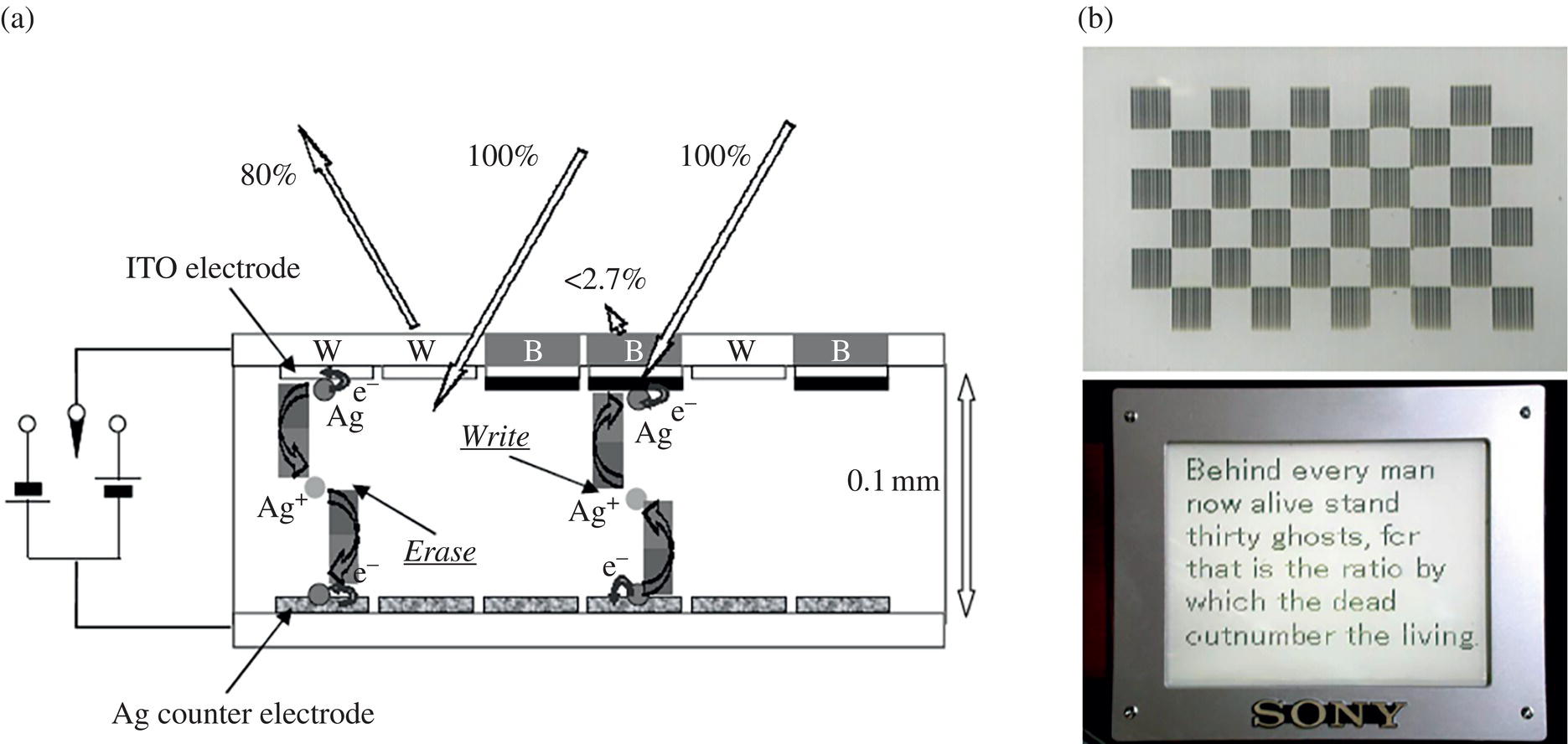
Figure 10.11 (a) Structure of Ag electrodeposition‐based EC display by SONY, (b) Photographs of a passive matrix display (50 dpi, 160 × 120 pixels). Each square in the upper image consists of 10 × 10 pixels [35] K. Shinozaki, 2002 / JOHN WILEY & SONS, INC.
Exciting results were reported in Ag electrodeposition in 2012 [36]. Although the black color was generally generated by the electrodeposition of silver ions, an EC device based on silver electro‐deposition that achieved three reversible optical changes (transparent, silver‐mirror, and black) in a single cell were successfully demonstrated (Figure 10.12). The driving principle of this EC device is the exploitation of Ag nano‐particle deposition on two different transparent electrodes: a flat indium tin oxide (ITO) electrode and a rough ITO particle‐modified electrode. The EC material, consisting of a gel electrolyte in which Ag+ is dissolved, is sandwiched between the two electrodes. The default state of this device is transparent, whereas by applying a negative voltage to either one of the electrodes, Ag is electrodeposited on the electrode surface. Following Ag deposition on the flat ITO electrode, the device becomes mirrored. Conversely, the device turns black when Ag deposition occurs on the ITO particle‐modified electrode, which has a rough surface. This can apply to smart window systems as well as displays. The EC device shows pretty nice cycling stability over 20 000 cycles (not examined more). Still, the EC device had poor color retention property under open‐circuit state (memory effect) because of dissolution of deposited Ag metal by Cu2+ ions, which improves cycling stability as redox material at counter electrode and mediator to facilitate the oxidation of Ag deposit. This shortcoming was improved by introducing anion exchange membrane [37] or electroactive counter electrode to avoid Cu2+ ions [38]. The improved device achieved a longer retention time of the colored state (>4 hours). It is effective to maintain the coloring state without electric power for practical applications such as e‐paper, smart window, etc.
Although progress toward multichromatic representation in full‐color EC displays has been reported, control of the multichromatic state using inorganic EC devices has been a few reported except a combination of nanocavity structure as described above. The optical state related to the color of the metal electrodeposit on the electrode depends on the metal particle size, shape, and coalescence between particles. Suppose the size and shape of the Ag nano‐particles electrodeposited can be controlled uniformly and homogeneously. In that case Localized surface plasmon resonance (LSPR) band of the Ag nanoparticles can be used as a tool to control multiple chromatic states because Ag nano‐particles are known to show various colors based on their LSPR. On this basis, by changing voltage application method to Ag electrodeposition‐based EC cell, a reversible multicolor changing phenomenon, from transparent to magenta, cyan, and yellow in addition to mirror and black states, based on controlling the size of Ag nano‐particles during electrochemical deposition was successfully demonstrated (Figure 10.13) [39–41].
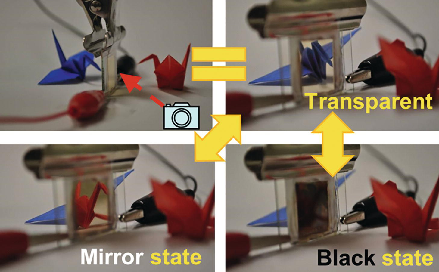
Figure 10.12 Digital camera images of Ag electrodeposition‐based EC cell. Upper left; Side view, Mirror state (−2.5 V application), Transparent state (before voltage application), Black state (+2.5 V application) [36] S. Araki, et.al, 2012 / JOHN WILEY & SONS, INC.

Figure 10.13 Digital camera images of Ag electrodeposition‐based EC cell exhibiting BCMY and mirror states (6 optical states). The cell structure is flat ITO electrode/Ag based electrolyte/ITO particles modified electrode. Constant voltage application to flat ITO electrode (Mirror), to ITO particles modified electrode (Black), and voltage‐step application to flat ITO electrode (Megenta to Cyan), to ITO particle modified electrode (Yellow) [39] A. Tsuboi, et.al, 2013 / JOHN WILEY & SONS, INC.
This clearly indicates that control of the morphology of Ag nano‐particles can lead to dramatic changes in color, as their size and shape influence the LSPR band. To improve color purity and chroma value, studies from the viewpoint of diffusion rate of Ag+ ions are conducted when Ag nano‐particles are electrochemically deposited. Consequently, well‐isolated Ag nano‐particles were obtained due to the slow growth rate by using an electrolyte with a low concentration of Ag+ ions, resulting in an improvement in the color quality of cyan and magenta [42]. Additionally, spherical Ag nanoparticles were deposited in the same device by optimizing their voltage application conditions, representing yellow and green colors. In particular, green coloration is a unique phenomenon because it can appear by combining two absorption peaks of LSPR. As a result of investigating the FDTD simulation, it was observed that the LSPR band in the long‐wavelength region was originated from the effects of the connection between Ag particles. The multifunction of this LSPR‐based EC display device could make it suitable for use in information displays and light‐modulating devices such as e‐paper, digital signage, and smart windows.
10.4 Summary
This chapter briefly reviews ECD technology, including cell structure, materials, and recent progress. The application of EC was mainly focused on the light‐modulating system such as dimming windows and car mirrors, although display application was reported over 25 years ago. However, growing interest in full‐color e‐paper and energy‐saving reflective display encourages research of EC and extends its possibility. Other several interesting materials and phenomena, rather than display applications, which are not covered in this chapter, are also emerging. These activate the research field and are believed to have the potential to generate unexpected attractive applications in the near future. We wish this chapter will help awaken interest for further investigations and applications of EC.
References
- 1 Rosseinsky, D.R. and Mortimer, R.J. (2001). Electrochromic systems and the prospects for devices. Adv. Mater. 13: 783–793.
- 2 Granqvist, C.G., Azens, A., Heszler, P. et al. (2007). Nanomaterials for benign indoor environments: Electrochromics for “smart windows”, sensors for air quality, and photo‐catalysts for air cleaning. Sol. Energy Mater. Sol. Cells 91 (4): 355–365.
- 3 Chua, M.H., Zhu, Q., Tang, T. et al. (2019). Diversity of electron acceptor groups in donor–acceptor type electrochromic conjugated polymers. Sol. Energy Mater. Sol. Cells 197: 32–75.
- 4 Liang, Z., Yukikawa, M., Nakamura, K. et al. (2018). A novel organic electrochromic device with hybrid capacitor architecture towards multicolour representation. Phys. Chem. Chem. Phys. 20: 19892–19899.
- 5 Liang, Z., Nakamura, K., and Kobayashi, N. (2019). A multicolor electrochromic device having hybrid capacitor architecture with a porous carbon electrode. Sol. Energy Mater. Sol. Cells 200: 109914‐1‐7.
- 6 Karaca, G.Y., Eren, E., Cogal, G.C. et al. (2019). Enhanced electrochromic characteristics induced by Au/PEDOT/Pt microtubes in WO3 based electrochromic devices. Opt. Mater. 88: 472–478.
- 7 Deb, S.K. (1969). A novel electrophotographic system. Appl. Opt. 8: 192–195.
- 8 Monk, P.M.S., Mortimer, R.J., and Rosseinsky, D.R. (2007). Electrochromism: Fundamentals and Applications. Wiley.
- 9 Wang, Z., Wang, X., Cong, S. et al. (2020). Towards full‐colour tunability of inorganic electrochromic devices using ultracompact fabry‐perot nanocavities. Nat. Commun. 11 (1): 302. ‐1‐9.
- 10 Zhang, W., Li, H., Yu, W.W. et al. (2020). Transparent inorganic multicolour displays enabled by zinc‐based electrochromic devices. Light Sci. Appl. 9: 121‐1‐11.
- 11 Sen, S., Saraidaridis, J., Kim, S.Y. et al. (2013). Viologens as charge carriers in a polymer‐based battery anode. ACS Appl. Mater. Interfaces 5 (16): 7825–7830.
- 12 Hagfeldt, A., Vlachopoulos, N., and Gratzel, M. (1994). Fast electrochromic switching with nanocrystalline oxide semiconductor films. J. Electrochem. Soc. 141 (7): L82–L84.
- 13 Kim, J.W. and Myoung, J.M. (2019). Flexible and transparent electrochromic displays with simultaneously implementable subpixelated ion gel‐based viologens by multiple patterning. Adv. Funct. Mater. 29 (13): 1808911–1808920.
- 14 Kim, J.W., Kwon, D.K., and Myoung, J.M. (2020). Rollable and transparent subpixelated electrochromic displays using deformable nanowire electrodes with improved electrochemical and mechanical stability. Chem. Eng. J. 387: 124145–124160.
- 15 Urano, H., Sunohara, S., Ohtomo, H. et al. (2004). Electrochemical and spectroscopic characteristics of dimethyl terephthalate. J. Mater. Chem. 14 (15): 2366–2368.
- 16 Kobayashi, N., Miura, S., Nishimura, M. et al. (2008). Organic electrochromism for a new color electronic paper. Sol. Energy Mater. Sol. Cells 92 (2): 136–139.
- 17 Watanabe, Y., Imaizumi, K., Nakamura, K. et al. (2011). Effect of counter electrode reaction on coloration properties of phthalate‐based electrochromic cell. Sol. Energy Mater. Sol. Cells 99: 88–94.
- 18 Watanabe, Y., Nagashima, T., Nakamura, K. et al. (2012). Continuous‐tone images obtained using three primary‐color electrochromic cells containing gel electrolyte. Sol. Energy Mater. Sol. Cells 104: 140–145.
- 19 Yashiro, T., Naijoh, Y. et al. (2011). SID2011 Digest, 42–45 and Proc. IDW2011, 2011: 375–378.
- 20 Kim, G.W., Kim, Y.C., Ko, I.J. et al. (2018). High‐performance electrochromic optical shutter based on fluoran dye for visibility enhancement of augmented reality display. Adv. Opt. Mater. 6 (11): 1701382–1701392.
- 21 Ko, I.J., Park, J.H., Kim, G.W. et al. (2019). An optically efficient full‐color reflective display with an electrochromic device and color production units. J. Inf. Disp. 20: 155–160.
- 22 Zhang, W., Wang, X., Wang, Y. et al. (2019). Bio‐inspired ultra‐high energy efficiency bistable electronic billboard and reader. Nat. Commun. 10: 1559‐1‐8.
- 23 Wang, Y., Wang, S., Wang, X. et al. (2019). A multicolour bistable electronic shelf label based on intramolecular proton‐coupled electron transfer. Nat. Mater. 18: 1335–1342.
- 24 Thompson, B.C., Schottland, P., Zong, K. et al. (2002). In situ colorimetric analysis of electrochromic polymers and devices. Chem. Mater. 12: 1563–1571.
- 25 Rauh, R.D., Wang, F., Reynold, J.R. et al. (2001). High coloration efficiency electrochromics and their application to multi‐color devices. Electrochim. Acta 46 (13): 2023–2029.
- 26 Bulloch, R.H., Kerszulis, J.A., Dye, A.L. et al. (2014). Mapping the broad CMY subtractive primary color gamut using a dual‐active electrochromic device. ACS Appl. Mater. Interfaces 6 (9): 6623–6630.
- 27 Liu, D.Y., Chilton, A.D., Shi, P. et al. (2011). In situ spectroscopic analysis of sub‐second switching polymer electrochromes. Adv. Funct. Mater. 21 (23): 4535–4542.
- 28 Beaujuge, P.M. and Reynolds, J.R. (2010). Color control in π‐conjugated organic polymers for use in electrochromic devices. Chem. Rev. 110 (1): 268–320.
- 29 Amb, C.M., Dyer, A.L., and Reynolds, J.R. (2011). Navigating the color palette of solution‐processable electrochromic polymers. Chem. Mater. 23 (3): 397–415.
- 30 Kim, D.S., Park, H., Hong, S.Y. et al. (2019). Low power stretchable active‐matrix red, green, blue (RGB) electrochromic device array of poly(3‐methylthiophene)/Prussian blue. Appl. Surf. Sci. 471: 300–308.
- 31 Lang, A.W., Österholm, A.M., and Reynolds, J.R. (2019). Paper‐based electrochromic devices enabled by nanocellulose‐coated substrates. Adv. Funct. Mater. 29 (39): 1903487–1903498.
- 32 Ziegler, J.P. (1999). Status of reversible electrodeposition electrochromic devices. Sol. Energy Mater. Sol. Cells 56: 477–493.
- 33 Imamura, A., Kimura, M., Kon, T. et al. (2009). Bi‐based electrochromic cell with mediator for white/black imaging. Sol. Energy Mater. Sol. Cells 93 (12): 2079–2082.
- 34 Nakashima, M., Ebine, T., Shishikura, M. et al. (2010). Bismuth electrochromic device with high paper‐like quality and high performances. ACS Appl. Mater. Interfaces 2 (5): 1471–1482.
- 35 Shinozaki, K. (2002). 5.5L: Late‐news paper: electrodeposition device for paper‐like displays. SID Symp. Dig. Tech.Pap. 33: 39–41.
- 36 Araki, S., Nakamura, K., Kobayashi, K. et al. (2012). Electrochromic materials: electrochemical optical‐modulation device with reversible transformation between transparent, mirror, and black. Adv. Mater. 24 (23): OP122–OP126.
- 37 Kimura, S., Onodera, R., Nakamura, K. et al. (2018). Improvement of color retention properties of Ag deposition‐based electrochromic device by introducing anion exchange membrane. MRS Commun. 8: 498–503.
- 38 Kimura, S., Nakamura, K., and Kobayashi, N. (2020). Bistable silver electrodeposition‐based EC device with a Prussian blue counter electrode to maintain the mirror state without power supply. Sol. Energy Mater. Sol. Cells 205: 110247‐1‐6.
- 39 Tsuboi, A., Nakamura, K., and Kobayashi, N. (2013). A localized surface plasmon resonance‐based multicolor electrochromic device with electrochemically size‐controlled silver nano‐particles. Adv. Mater. 25 (23): 3197–3201.
- 40 Tsuboi, A., Nakamura, K., and Kobayashi, N. (2013). Chromatic characterization of novel multicolor reflective display with electrochemically size‐controlled silver nano‐particles. J. Soc. Inf. Disp. 21 (7–9): 361–367.
- 41 Tsuboi, A., Nakamura, K., and Kobayashi, N. (2014). Multicolor electrochromism showing three primary color states (cyan–magenta–yellow) based on size‐ and shape‐controlled silver nanoparticles. Chem. Mater. 26 (22): 6477–6485.
- 42 Kimura, S., Sugita, T., Nakamura, K. et al. (2020). An improvement in the coloration properties of Ag deposition‐based plasmonic EC devices by precise control of shape and density of deposited Ag nano‐particles. Nanoscale 12 (47): 23975–23983.