
CHAPTER 10
Project Integration
In this chapter, our goal is to take three previous projects and combine them into one package, both in terms of hardware and software. The three projects are: 1) the PS2 keyboard keyer, 2) the CW decoder, and 3) the station clock/ID timer. You could easily integrate the capacitive keyer you built in Chapter 8, but we wanted to find a middle ground between the complexities of integration and narrative clarity. Three projects are enough complexity to illustrate the issues of integration, but simple enough to make the discussion clear. Also, many rigs already have a keyer integrated into them so there is less need to add that feature in this project.
One of the primary purposes of this chapter is to discuss some of the issues you need to think about when doing a more complex project. On the surface, the idea of project integration seems simple enough: take the code from the three projects, cut-and-paste the code together, and stack the three shields onto a board in a huge “Arduino Sandwich” and you’re done! Right?
Well, not really. There are a number of complications that make it a little more difficult than it might seem at first blush. First, the three independent projects discussed in earlier chapters now have to “play nice” with each other and share resources. Second, there’s almost too much hardware and software for a simple ATmega328 μC. While there’s more than enough Flash memory to shoehorn all of the source code into a 328 board, it would be running on the ragged edge of the board’s other resources (especially SRAM) and that’s almost never a good idea. Third, this is a good opportunity to introduce you to a board based on the ATmega2560 (simply “2560” from now on) for the first time. The 2560 has 256 kb of Flash memory (minus 8 kb for the bootloader), 8 kb of SRAM, and 4 kb of EEPROM. Cap it off with 54 digital I/O pins plus some additional nice features (e.g., more interrupt pins) and you’ve got a substantially deeper resources pool at your disposal. Despite the resource depth of the 2560, the board can be purchased online for less than $15.
For this project, we have also elected to use an Arduino Expansion shield from DFRobot, as shown in Figure 10-1. The shield allows you to add up to four independent shields on a single board without the need to stack the shields. Not only does the expansion board do away with most heat issues that might arise from using the Arduino Sandwich approach of handling multiple shields, it also gives you a few more nano-acres of board real estate to work with. If you look closely at Figure 10-1, you can see how four shields can be fit onto the board. Each station on the board has its own 5 V and GND point, which makes it easier to power each shield on the board. The 2560 plugs into the board from below (you can see the outline of the 2560’s pins), and the tie-ins for the 2560 are shared across the board. That is, for example, not all of the analog pins are dedicated to a single shield but are distributed across all four stations. The same is true for the interrupt pins. It’s a perfect solution for our integration project. You can still use the stacked shield approach if you wish; it’s just that the DFRobot shield makes it easier to build.

FIGURE 10-1 The DFRobot Mega-multi Expansion shield. (Shield courtesy of DFRobot)
Because we’ve already discussed these projects in previous chapters and because hardware and software elements are much the same as before, we concentrate our focus in this chapter on the issues that arise when multiple projects with different feature sets must share a limited resource pool. Both the hardware and software are affected when combining the three projects that must now share a single processor.
As usual, we discuss the hardware issues first and then the software. Unlike our earlier projects, however, this project requires multiple source code files … something we haven’t done before. The Arduino IDE has some fairly strict rules we must follow to allow a single project to have multiple source code files and we discuss those rules as well. Because the Arduino IDE is happiest with *.cpp (i.e., C++) files when there are multiple source files in a single project, we also show you the conventional form used for such source code and header files. At the close of the chapter, we bring it all together in an integrated project.
Integration Issues
First, from an operational approach, we want to view the hardware aspects of each project as being etched in stone. That is, we assume that you have already built the three projects as a set of stand-alone shields. From our perspective, this means that we want to use the shields as they already exist, making as few changes to the hardware as possible. We know that we must make some changes, but we want to minimize those changes as much as we can.
Second, because we have software with multiple tasks to solve, and yet must function within a single memory space, those functions need to be handled a little differently. That is, when each project stood as a solution to a single task, we didn’t have to worry about interaction effects with other elements of the software. We had little concern about sharing the limited board resources. Not so when you wish to combine multiple projects onto a single processor. Also, initially we wrote those software solutions with little regard to scalability (the ability to alter the scope of a project); we didn’t write the code with the intent of adding disparate functionality at a later date. As a result, we do need to make some software changes in the way a given shield interacts with the other shields.
Because different projects often use the same pins, pin conflicts are often an issue when you try to integrate multiple projects into one larger project. Appendix C presents a list of the Arduino pins that are used for each of the various projects. A quick look at the table should help you understand where a pin conflict may arise. Creating your own table is not a bad idea as you start to develop projects of your own.
Finally, it is the software that’s going to have a large impact on how well each element of the hardware plays with the other elements. The word “integration” in the chapter has substance. If we didn’t care about the interplay between projects in a software realm, we could have titled the chapter “Project Stacking.” If we just wanted to put three projects into one box, that’s a much simpler task. We could, for example, have two dedicated LCD displays; one for the RTC and one for the decoder. However, if we want to share resources between tasks, the software needs some refinement. Sharing resource takes a little more “software thought” and that’s what we need to address first in this chapter.
The Real Time Clock (RTC) Shield
In order to communicate with the DS1307 RTC module discussed in Chapter 4, we used the I2C interface. Using the I2C interface also means we needed to use the Wire library for the Arduino. Table 10-1 shows the connections the Wire library expects when using different Arduino boards.
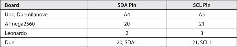
TABLE 10-1 The I2C Interface and Arduino Boards
Because the 2560 uses a different set of I/O pins for the I2C interface than the Uno or Duemilanove, we need to modify the pin assignments used by the I2C clock (SCL) and data (SDA) pins.
Another complication is that we used a dedicated LCD display for both the RTC and the CW decoder. While we could keep both displays, that seems redundant. To that end, and not wanting to move the display lines for the LCD display, we now have a decision to make. The SDA and SCL lines are available at every station on the expansion board. By doing this, DFRobot makes the I2C interface available to all shields that might be placed on the expansion board. This makes sense because the I2C interface is a shared bus and can use the 2560 as the Master and each of the support shields could have its own I2C Slave device on it. In that sense, it doesn’t matter where we place the RTC shield. As far as the I2C wiring goes, all we need to do is tie the SDA and SCL lines on the expansion board (i.e., pins 20 and 21) to the corresponding lines on our RTC shield (pins A4 and A5). Rather than constructing a new RTC shield, we simply attached Dupont jumpers from pins 20 and 21 on the expansion board to pins A4 and A5 on the existing RTC shield.
While the I2C interface demands the use of certain pins, it matters little which I/O pins are used for the LCD display. In earlier projects, we chose to use the pin arrangement shown in row one (i.e., the 328 row) of Table 10-2. Because the examples provided with the Arduino IDE LiquidCrystal library tend to use pins 12 and 11 for the Register Select (RS) and Enable (EN) pins, we used those same pins when we constructed the LCD display in Chapter 3. We did retain the data pins 5-2 for the previous projects. We did this because most Arduino examples use these pins.
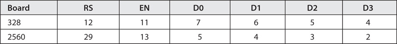
TABLE 10-2 The LCD Display Pin Map
If you view the expansion board with its labeling correctly oriented for reading, we ended up with the RTC shield in the North-West corner (position 1) of the expansion board. As long as you are aware of the pin placements, you could place the RTC shield in any one of the four positions (see Table 10-3). Keep in mind, however, that if you place the expansion board in a case and keep the LCD display “on board” the RTC shield, its position on the expansion board dictates where the display appears on the case. If that positioning poses a problem for your design, you can always “cable” the connections to the LCD display to the LCD shield and move the display to whatever position makes sense for your design. (We used this cabling approach for the LCD display for the Dummy Load project in Chapter 6.)
The pushbutton switch used to reset the station ID timer can use any I/O pin you wish as long as you remember to change the program source code accordingly. We elected to use pin 28 simply because it’s available at the N-W position on the expansion board.
CW Decoder Shield
The decoder shield uses analog pin A5 as its input from the speakers. The A5 analog pin on the expansion board is found at the South-West position (2) on the board. For that reason, we placed the decoder shield at the S-W position of the expansion board. However, because pin A5 on the decoder shield does not line up with A5 on the expansion board, we soldered a small jumper between the two pins on the decoder shield.
Because we intend to share the LCD display on the RTC board with the decoder shield, we simply unplugged the decoder LCD display from its socket header. Whatever output might be generated by the decoder shield is routed to the RTC shield using the same LCD object (i.e., lcd) we create in software. From the perspective of the decoder shield, it appears that the LCD shield is the same as before. The multiple use of the LCD display is our first example of a shared resource in this project.
PS2 Keyboard Keyer
The shield used for the PS2 keyer is almost unchanged. We did move the PS2 socket for the keyboard from the shield itself to a case-mounted socket. Because there are no special pin requirements you are free to place the shield at either of the two remaining positions. Figure 10-2 shows that we opted for the North-East position (4) on the expansion board. You can see the off-board PS2 socket on the right side of Figure 10-2. The two wires leading away from the same shield go to the jack for the keyed circuit.
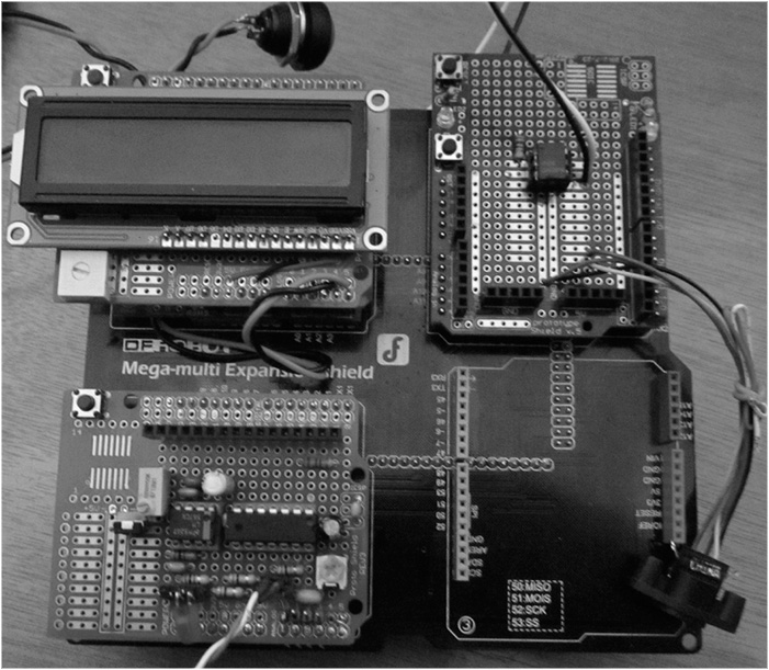
FIGURE 10-2 The three project shields on the expansion board.
The Expansion Board
The RTC shield is in the upper-left corner of Figure 10-2 and holds the LCD display for both the RTC and the CW decoder. You can also see the pushbutton switch that is used to reset the station ID timer connected to the RTC shield. In the same figure, the bottom-left corner is occupied by the CW decoder shield with its LCD display removed. The two wires from the shield are ultimately connected to the speaker of the transceiver. The 2560 μC board is “under” the expansion board. As you can see, the S-E position of the expansion board is empty. If you have some other project that you would like to add to the integrated project, you could use that position.
You should keep in mind that using three shields produces an increased power load on the supporting 2560 board. For that reason, we encourage you to use an external power source (e.g., a wall wart) plugged into the external power connector on the 2560 board. Because the 2560 board has its own voltage regulator, you can use any source capable of supplying 7 to 12 V. (The regulator can handle higher voltages, but it’s not a good idea to stray too far from the 7-12 V range. The maximum current on the regulator is about 1 amp.)
Table 10-3 shows how the DFRobot expansion board maps to the 2560 pins. Table 10-3 allows you to determine which pins are available for each of the four positions on the expansion board.
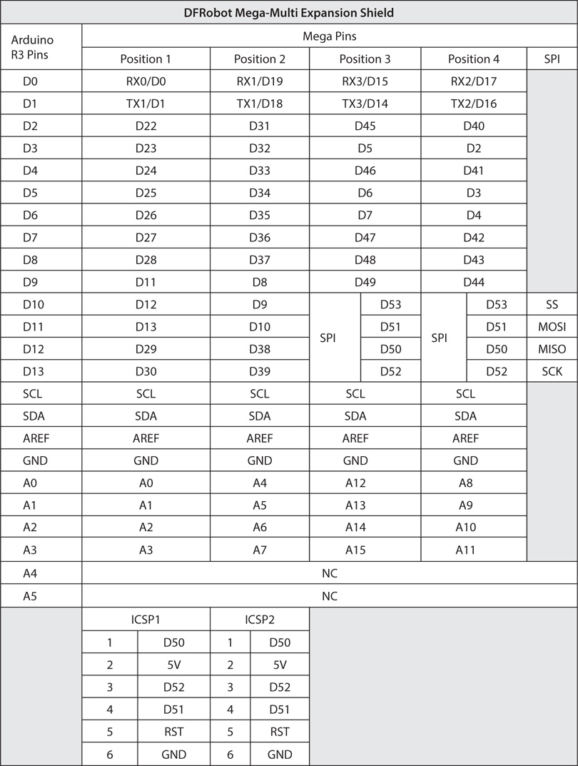
TABLE 10-3 DFRobot Mega-Multi Expansion Shield Pin Mapping
Software Project Preparation
We don’t know how you have organized the available source code files for the projects in this book. The way we have them organized is with the main directory named P-KHamRadioBook as the main directory and then a chapter number for each chapter in the book. Within each chapter we have additional directories for topics of interest in that chapter. For example, we use the E: drive as our primary storage drive and we named this project “IntegrationCode.” Therefore, our directory for the code in this project is:
E:/P-KHamRadioBook/Chapter10/IntegrationCode
Into that directory, we copied each of the source code files from the other related chapters. There is a file for each chapter project: 1) the decoder chapter (e.g., Decoder.cpp and Decoder.h), 2) the PS2 keyer (PS2Keyer.cpp and PS2Keyer.h), and 3) the RTC (RTCTimer.cpp and RTCTimer.h). In addition, we have the main project file, IntegrationCode.ino, and its associated header file IntegrationCode.h. You can copy these files from the McGraw-Hill web site for this book or make empty files using a text editor. Eventually, of course, you’re going to have to add in the source code, so you may as well download the source code files now if you haven’t already done so.
There are three rules you must follow when using multiple source files in a single project. First, all of the source files used in the program sketch must appear in the directory that uses the same directory name as the name of the sketch. In other words, because we have named this program sketch IntegrationCode, the Arduino IDE wants all of the files used in the program to reside in a directory that shares the same name as the project file. For us, the result of our directory looks like:
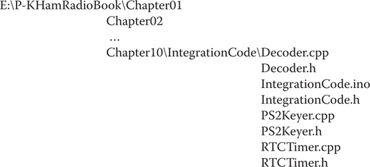
If you use this structure for your source files, when you load the IDE and then load the IntegrationCode program sketch, all of the files in the Chapter 10 directory appear as tabs in your IDE. If you’ve done things correctly, your IDE should look similar to Figure 10-3. Notice the multiple tabs just above the source code window. You should see one tab for each of the files in the IntegrationCode directory.
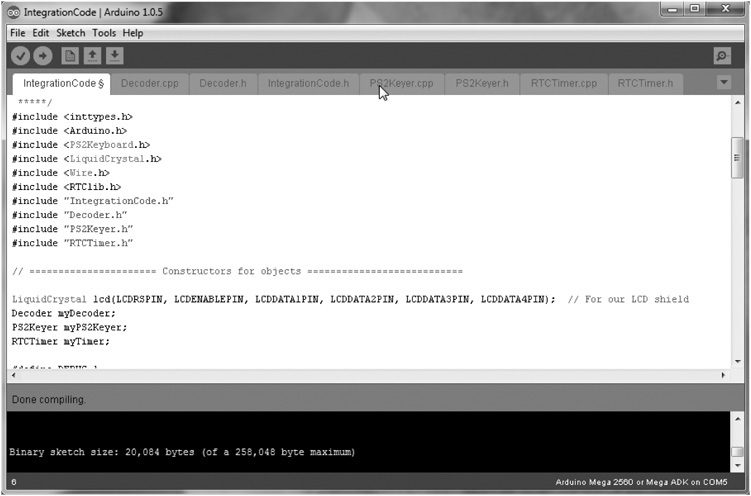
FIGURE 10-3 The Arduino IDE with IntegrationCode sketch loaded.
The second rule is that there can only be one *.ino file for each sketch, regardless of how many source code files there are in the program sketch. As you already know, the name of the *.ino file must be the same as the directory that holds the *.ino file. In our case, the directory holding the source files is IntegrationCode, so the *.ino file must be named IntegrationCode.ino. Using this *.ino naming convention also means that the IDE expects to find the setup() and loop() functions in the file bearing the ino secondary file name extension. (Actually, the C++ compiler that lurks below the Arduino IDE surface uses the ino information to log the file associated with the main() function, which is the primary entry point for all C and C++ programs.)
The third rule is that the IDE wants any file other than the *.ino file to be either a C or C++ source code file (i.e., uses the *.c or *.cpp secondary file name) or a C or C++ header file (i.e., uses the *.h secondary file name). Any other files in the directory are simply ignored.
Okay, because the IDE can use either C or C++ files, which should you use? The easy answer is to use the language you’re comfortable with. We’ve been using C for almost 40 years now, so we are quite comfortable with it. However, C++ and Object-Oriented Programming (OOP) in general bring so much to the table, we have elected to build our integration project using C++. What follows is a brief explanation of some of the software idioms that C++ uses. If software just isn’t your thing, you can skip the next section if you wish. However, we think understanding the OOP at some level helps you understand the ins-and-outs of this program and may help you to create your own projects down the road.
C++, OOP, and Some Software Conventions
First, we should admit that you could build this project using plain C and it would probably work just fine. Given that, why mess around with C++? The first reason is because the compiler behind the Arduino IDE is based on a C++ compiler. Knowing something about C++ lets you take advantage of some of the features that C++ offers. Second, C++ is an OOP language. We touched on some of the advantages OOP has in Chapter 2, but we actually use some of them in this chapter. Third, most of the libraries are written in C++. Reading and understanding their source code should better equip you to use those libraries. After all, being able to stand on the shoulders of others makes seeing things a whole lot easier. Finally, once mastered, practicing OOP principles and techniques in your own programming efforts is going to produce better code that is more easily maintained. To learn OOP in general and C++ specifically takes some time, but is well worth the effort. With that in mind, let’s dive in and get our feet wet …
C++ Header Files
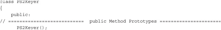
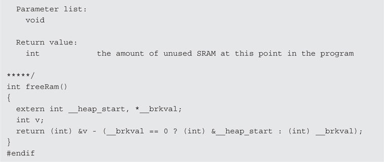
A header file contains information that is required for its associated program file to work properly in the environment for which it is defined. Many beginners tend to place program code in their header files, and that’s not what they are intended for. Instead, they are used to provide overhead information that the compiler needs to do its job effectively. Listing 10-1 presents the header file (PS2Keyer.h) associated with the PS2 keyer source code file (PS2Keyer.cpp).
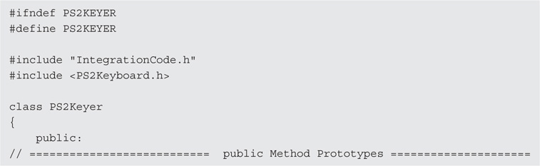
LISTING 10-1 The PS2Keyer.h header file.
The first line in the header file is a preprocessor directive. All preprocessor directives start with a sharp (or pound) sign (#). Recall that preprocessor directives do not use the semicolon to terminate the directive. The directive ends at the end of the line holding the directive. That’s one reason that we call them a directive rather than a statement. Most C++ and C programmers write the directive in a way that makes the directive fit on a single line, as you see in the first line of Listing 10-1. You can continue a long directive to a second line if the first line ends with a single backslash character (), but most programmers tend to avoid multiline directives.
#ifndef … If Not Defined
The #ifndef directive is used like a normal if statement in that it can be used to toggle directives and statements into the program. The general form is:

If expression1 is not defined at this point in the program, everything that follows the directive up to the #endif is compiled into the program. If you look at Listing 10-1, you might be wondering where the #ifndef’s matching #endif is. Look at the last line in Listing 10-1. What this means is that everything that appears between these two preprocessor directives is compiled into the program, provided that PS2KEYER is not defined at this point in the program. In this file, the first preprocessor directive controls all of the statements in the header file!
Wait a minute! The very next preprocessor directive #define’s PS2KEYER. What’s the purpose of that? Think about it. Suppose you included this header file two times in the same program by mistake. You would end up defining everything in the file twice, which would cause the compiler to generate a bunch of duplicate definition error messages. Using this technique makes it impossible to “double include” the contents of the header file. You will see this idiom used in most library files.
#include Preprocessor Directive … Read a File into the Program
The #include preprocessor directive causes the compiler to read the specified file into the program at that point. In Listing 10-1 we see:
#include “IntegrationCode.h”
#include <PS2Keyboard.h>
This tells the compiler to open and read both the integrationCode.h and the PS2Keyboard.h header files into the program. The compiler opens those files and behaves as though the contents of those two files appear at this exact point in the program as part of the source code.
Why is the first file name surrounded by double quotation marks (“”) but the second file name is surrounded by angle brackets (< >)? The double quotation marks tell the compiler to look in the current working directory to find the IntegrationCode.h file. For our program, that file is indeed in the current working directory, because that’s where the *.ino file is located. By default, the location of the *.ino sketch file defines the location of the current working directory.
When angle brackets surround a file name, that tells the compiler to look in the default include directory for the file. For the Arduino IDE, such files are typically found in the Arduinolibraries directory.
Class Declaration
The next few lines in the header file are:
The first line says that we are about to declare a formal description of an C++ class named PS2Keyer. Everything after the opening brace ({) through to the closing brace (}, near the end of the file) tells what we can expect to find in the PS2Keyer class.
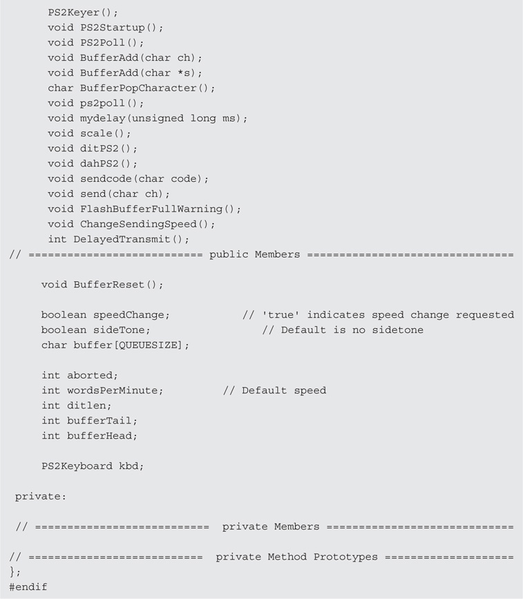
public and private Members of a Class
The keyword public followed by a colon character (:) states that the following items are public members of the class. The term member means that a specific variable or method “belongs to” the class. The public keyword means that those things that have the public attribute are accessible at all points in the program. You can also think of public meaning that any public variable or method as having global scope. If you look a little farther down in Listing 10-1, you find the keyword private followed by a colon. The keyword private means that only program elements (e.g., methods) declared between the opening brace and closing braces of the class declaration have access to the items designated as private. The PS2Keyer class does not have any private members or methods.
Function Prototypes
If you look a few lines farther down in the public section of the class declaration, you find the statement:
void BufferAdd(char ch);
This is called a function prototype. A function prototype consists of the data type the function returns (void in this case), the name of the function (BufferAdd), and the parameters (if any) that are used when calling the function (char ch). (Sometimes you may hear everything from the function name to the end of the statement referred to as the function signature.)
Why have function prototypes? The reason is that function prototypes can help you from shooting yourself in the foot. How so? Well, after reading the function prototype, the compiler knows that the function named BufferAdd cannot return a value to the caller because its return type is void. The compiler also now knows that this function requires precisely one parameter and it better be a char data type or it’s going to let you know about it. Essentially, prototypes enable the compiler to verify that you are using the class functions in the way in which they were intended to be used. This process of checking the function signature against how you are actually using the function is called type checking.
Some OOP jargon is in order. To make a distinction between C functions and C++ functions defined within a class, most programmers refer to a “function” declared within the class as a method. As a memory-jogger, just remember that “methods have class.”
As mentioned earlier, another OOP piece of jargon is to refer to the data defined within the class as members of the class. Therefore, the lines:

define specific members of the PS2Keyer class because they are defined within the braces of the class. Because they are defined within the public access specifier’s purview, they are more specifically referred to as public members of the PS2Keyer class. Whereas plain C likely refers to the data definitions as simply variables, data defined within a class are members of the class.
cpp Files
You saw earlier in this chapter that the program sketch ended with the ino secondary file name and that each source code file ended with cpp. The C Plus-Plus (cpp) files contain the actual code for a particular class. While you could define code in the header file, that practice is frowned upon. Instead, the actual class code normally is found in the cpp files. Listing 10-2 contains part of the PS2Keyer.cpp file.
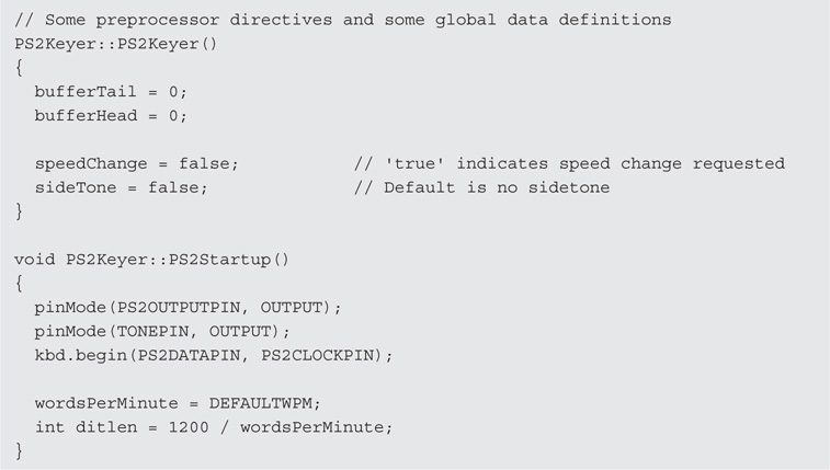
LISTING 10-2 PS2Keyer class source code (partial listing).
Class Constructor Method
Every C++ class has a class constructor. You can identify the class constructor by two of its characteristics: 1) it always has the same name as the class, and 2) it is never allowed to have a type specifier. That is, the constructor can never return a value and it can’t even use the keyword void. The interesting thing is that, if we had not written the constructor you see in Listing 10-2, the compiler automatically would have written one for us. Equally interesting is the fact that, if you look for this “automatically generated” constructor, you’ll never find it. That’s why we sometimes call it the ghost constructor.
Really? If the compiler can automatically write a constructor for us, why do we need to write one? Well, in many cases, you don’t. The primary responsibility of the ghost constructor is a default initialization of all data members of the class. That is, all data types are initialized either to 0, false, or null, whichever is appropriate for the data type in question. However, there will be times when you’re not happy with those default initialization values. That’s when you should write your own constructor. You would write your own constructor when you want the class object to come to life with a specific, known, state that you want to control.
The first line in Listing 10-2 is:
PS2Keyer::PS2Keyer()
Verbalizing this line actually makes more sense if you read it from right to left. Doing so, we might verbalize this line as: “The PS2Keyer() method belongs to the PS2Keyer class.” You know that it is a method because of the two parentheses following the method’s name. You also know that it is the class constructor method because it has the same name as the class itself. The two colon characters (::) are formally called the “scope resolution operator.” The purpose of the scope resolution operator is to tie the method named PS2Keyer() to the class named PS2Keyer. For us, it makes more sense to verbalize the scope resolution operator as the “belongs to” operator when reading from right to left. Verbalize it in whatever way makes the most sense to you.
As we just pointed out, the PS2Keyer() method shares the same name as the class and, hence, must be the class constructor. Notice that we initialized four members of the class in the constructor. Technically, we didn’t need to write a constructor at all. The reason is because the default initialization values that would have been used by the ghost constructor are the same values we used. We wrote our own constructor simply to show you how you can write a constructor and use it to assign whatever values you wish to class members.
So, what does the following line tell you?
void PS2Keyer::PS2Startup()
This line tells you that: “PS2Startup() is a method that takes no parameters, returns a void data type, and is a method that belongs to the PS2Keyer class.” The statements that appear between the opening brace ({) and closing brace (}) of the method hold the statements that are designed to fulfill the task that this method performs.
If you look through the PS2Keyer.cpp file, you can see the task each method is designed to perform. The other *.cpp files follow the same C++ conventions. The actual code in the class methods is pretty much “pure” C code. We encourage you to download and review the code in each of the source files so you have an understanding of how C++ files are constructed and their purpose. It will be time well spent.
IntegrationCode.ino
The sketch file for the integration program is IntegrationCode.ino. Like all other Arduino IDE projects, the primary purpose of the *.ino file is to hold the code that initiates and controls the program. The *.ino file is always the file that contains the setup() and loop() functions that are common to all Arduino programs. Using multiple source code files doesn’t change the purpose of the *.ino file. Listing 10-3 presents the code for IntegrationCode.ino.
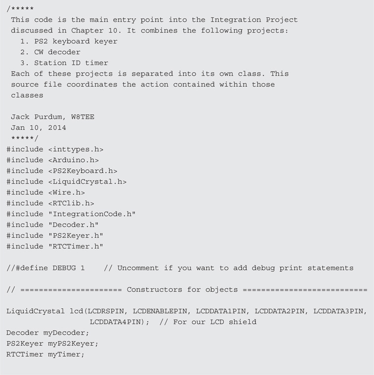
LISTING 10-3 Source code for IntegrationCode.ino.
Header Files
The code begins with a number of #include preprocessor directives. Most of the calls are to include special library header files used in the program. The header files surrounded by double quotation marks are the header files we wrote and appear in the working directory. Note that some of the header files are “nonstandard.” That is, they are associated with special libraries that are not included as part of the standard Arduino library files. If you haven’t downloaded those libraries yet, please refer to the chapter that discusses the related project to find where you can download the necessary library file.
The next four statements in Listing 10-3 are:

Constructors
You’ve used the LiquidCrystal statement before, in your projects that used the LCD display shield described in Chapter 3. Actually, each of the four statements above are calls to the class constructor for each class used in this project. The LiquidCrystal constructor passes in six parameters that are used to initialize specific members of the LiquidCrystal class. The other three constructor calls do not use any arguments when their constructor is called.
When these four statements are finished executing, chunks of memory will have been reserved for lcd, myDecoder, myPS2Keyer, and myTimer. In OOP parlance, these four statements instantiate an object for each class. The process of instantiating an object is the duty of the class constructor. The result of instantiation is an object of that class.
How the Terms Class, Instantiation, and Object Relate to One Another
When readers first start using OOP practices in their coding, many are confused about the terms class, instantiation, and object. Actually, understanding each item is pretty easy. First, a class is a description of what an object of that class is and can do. For example, suppose you wanted to create a cookie cutter class. You would likely use a header file (e.g., cookiecutter.h) to describe the members and methods of the class. Your file would follow the same general form shown in Listing 10-1. Next, you would then proceed to specify in detail how each member and method works in the class using the code in the class code file (e.g., cookiecutter.cpp). Again, you would probably follow something similar to the style shown in the partial listing shown in Listing 10-2. When you have finished writing the *.h and its associated *.cpp file, you have a “blueprint” for the class. The members of the class are variables defined within the class that are capable of holding specific values, like the thickness of the cookie cutter metal, the number of bends in the metal, the angle of each bend, and so forth. The methods defined within the class describe the actions you want the cookie cutter class to be able to perform (e.g., pressCutterIntoDough(), ejectCookieFromCutter(), frostTheCookie()). Some people like to think of class members as nouns and class methods as verbs.
The important thing to understand is that a class is simply a description, or a template, of an object. Just as blueprints describe what a house will look like, blueprints themselves are not a house object. Likewise, a class description provides the details about the class in the *.h and *.cpp files, but the class description is not an object of the class. Think of a class as a set of blueprints for an object of the class.
The term instantiation refers to the process of actually creating an object of the class. Object instantiation occurs when the class constructor is called. When the class constructor finishes its job, there is a chunk of memory set aside for an object of that class. In other words, that chunk of memory is the object of the class. When the four statements above finish executing, the four class objects, lcd, myDecoder, myPS2Keyer, and myTimer, are available for use in your program.
Using our cookie cutter class analogy, the cookie cutter is described by the class *.h and *.cpp files. Your code calls the cookie cutter class constructor, which is the same as you picking up the cookie cutter and pushing it into some dough. After you’ve squiggled the cookie cutter around in the dough, you pull the cookie cutter away, which is the process of instantiation. You then shake the cookie cutter lightly and a raw cookie falls onto the cookie sheet. That cookie is the object of the class. Therefore, the class describes the exact cookie cutter you want to use, and in front of you is a huge sheet of dough (i.e., SRAM); you push the cookie cutter into the dough (instantiation) and extract an object called a cookie (e.g., lcd, myTimer).
The Arduino IDE provides a number of predefined classes for you to use, many of which you can see in the libraries subdirectory of the Arduino main directory. (If you want to find information on other class libraries, just Google “Arduino class libraries.” We got over a million and a half hits!) The other *.h and *.cpp files in the IntegrationCode project are descriptions of how we want each object to perform in the program. Because most of the code is simply a repeat of the code from earlier chapters, we don’t repeat it here. However, you should download the code and spend a little time looking at it. If you keep the discussion presented here in your mind as you examine the source code, you will find there is nothing mysterious about using OOP in your projects.
The Dot Operator (.)
Below are several statements from the setup() function presented in Listing 10-3.

All five statement lines begin with the name of a class object that was defined earlier in the program. Let’s look at the statement:
![]()
as an example of what the five lines are doing. First, note that the class object is named myPS2Keyer. As we said earlier, there is a chunk of memory associated with that object named myPS2Keyer caused by the instantiation process that takes place when the class constructor is called.
The dot operator is the period that you see between the class object’s name (myPS2Keyer) and the class method named PS2Startup(). We like to think of the dot operator as being verbalized with the words “fetch the memory address of.” With that in mind, you can verbalize the entire statement as: “Go to the memory address allocated for myPS2Keyer and fetch the memory address of PS2Startup().” Because PS2Startup() is a method defined within the class, the program takes the memory address it just fetched, jumps to that memory address, and starts executing whatever code it finds at that address. If you look at Listing 10-2, you can see the statements associated with the PS2Startup() method.
Some people find it useful to think of the dot operator as a “table of contents” for a class. That is, if myPS2Keyer corresponds to a book, the dot operator serves as a table of contents where you can find each member and method that belongs in the book (i.e., the class). Each entry in the dot operator’s table of contents is a memory address of where to find a specific member or method. Use whatever imagery for the dot operator that works for you.
If you look at Listing 10-1, the PS2Keyer header file contains the statement:
int wordsPerMinute;
Now suppose you wanted to change the words per minute being sent by the PS2 keyer to 20 words per minute. How would you do it? To answer that question, look at it from the compiler’s point of view: What does the compiler need to know to change the current value of the class member variable? The compiler needs to know three things: 1) where does the wordsPerMinute member variable of the myPS2Keyer object live in memory? 2) how many bytes of memory are associated with that member variable? and 3) what is the new value to assign to the member variable?
You already know that the expression:
myPS2Keyer.
says: “Go to the memory address of myPS2Keyer and fetch the memory address of …” So, part 1 of the things the compiler needs to know is now resolved. Part 2 asks how big the variable is. Well, the type checking the compiler performed when it read (and memorized!) the header file tells it that wordsPerMinute is an int, so the compiler already knows that two bytes are associated with the class member variable named wordsPerMinute. Part 3 is the value we wish to assign into the variable, which is 20. Therefore, we can complete the statement to assign the wordsPerMinute class member a new value of 20 by writing:
myPS2Keyer.wordsPerMinute = 20;
You can verbalize the statement as: “Go to the memory address assigned to the myPS2Keyer object and fetch the memory address of the two bytes associated with wordsPerMinute and assign the value 20 into those two bytes of memory.”
Suppose you want to read the new value for the wordsPerMinute class member. To retrieve the class member value for wordsPerMinute, you would use:
int val = myPS2Keyer.wordsPerMinute;
As you can see, there is nothing mysterious about using classes or OOP in general. The dot operator always appears between the class object name and the member or method name you are trying to access. It just takes a little practice and a slightly different way of thinking about how to write code. Before reading on, spend some time reviewing the code in the header and source code files for this project. With a little practice, we think you will find that OOP code is pretty easy to understand.
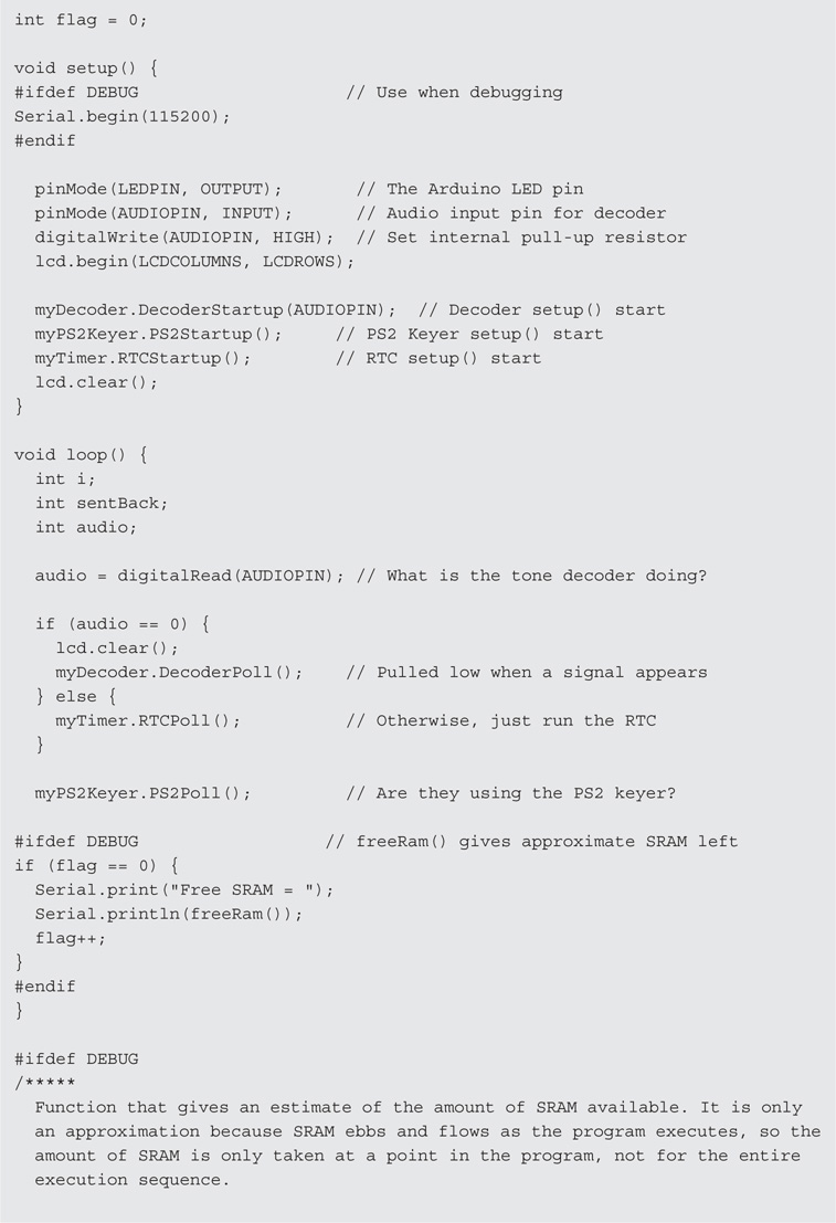
The loop() Function
Listing 10-4 repeats the loop() function code from Listing 10-3 so you don’t have to flip back and forth while reading the code description.
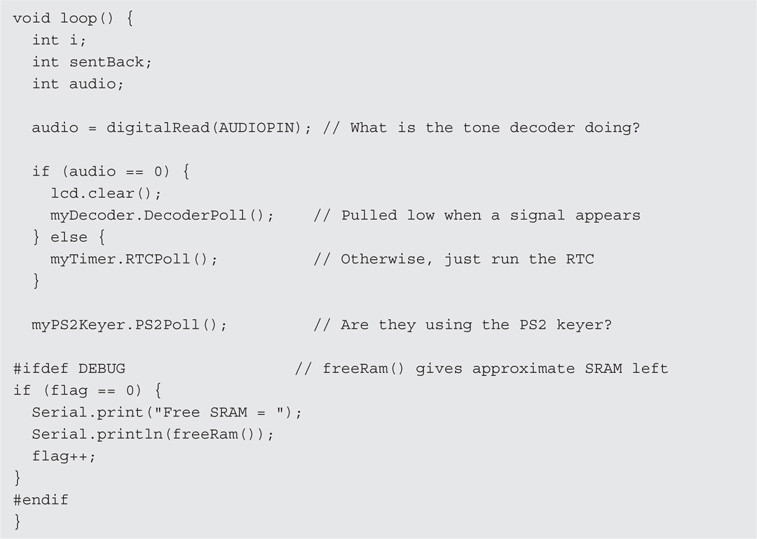
LISTING 10-4 The loop() function source code.
The loop() function begins by defining a few working variables and then calls digitalRead() to see if there is a signal on AUDIOPIN, which is the pin that is tied to the receiver’s speaker. Because of the way the hardware on the decoder shield and software work, variable audio holds the value 1 when there is no signal present on the speakers. In that case, the statement:
![]()
is executed. You should be able to verbalize what this statement does. If you look at the class code for the myTimer object, you can see that the method RTCPoll() updates the RTC and moves the appropriate data to the LCD display. If you compare the code found in the RTCPoll() method, you will discover that it is almost identical to the code found in the loop() function in Listing 4-1 in Chapter 4.
If audio equals 0, the myDecoder.DecoderPoll() method is called and the display switches away from the date and time and begins displaying the Morse code associated with the signal being received. Because of the way we wrote the DecoderPoll() method, as long as the decoder shield is reading Morse code, the program continues to process and display the translated Morse code. When the code stops, control returns to loop().
When control returns to loop(), the program checks to see if the PS2 keyer is active. If so, control remains in PS2Poll() until the PS2 keyer stops sending code, at which time control returns to loop() and another iteration of the code is begun.
Listing all of the source code here would be repetitive for several reasons. First, the code is little changed from the chapters that presented the original projects. Second, you should be able to read and understand what the code is doing now that you know how OOP works. Again, we urge you to spend a little time with the code so you can see how multiple source files can be used in a single program sketch.
Conclusion
As you experiment more with μCs, you will want to develop larger and more complex projects. While you could keep all of the code in one large, monolithic source file, you will discover that using multiple source files and OOP techniques makes developing such projects much easier. Breaking down a large task into a series of smaller tasks always makes that task seem more manageable. You will also discover that OOP techniques make debugging a project a lot easier, too. A final benefit is that, done with a little thought, you might be able to reuse the code in other projects.
There is no way that we can give C++ and OOP in general its due in a few pages. Our goal here was to give you enough OOP understanding to be able to read the code associated with OOP and C++ source code files. There are a number of C++ tutorials available on the Internet if you’d like to learn more about C++. Once the penny drops relative to all that OOP brings to the table, you’ll never code any other way.