
CHAPTER 8
A Morse Code Decoder
The project discussed in Chapter 7 is a straight Morse code keyer that automatically generates dits and dahs for you according to the paddle lever you press. As interesting as those projects may be in and of themselves, they aren’t terribly useful if you can’t read Morse code.
The project for this chapter is a Morse code decoder. The function of a Morse code decoder is to read CW signals on some frequency, translate the dits and dahs into the appropriate ASCII characters, and display them on some output device (e.g., the LCD display from Chapter 3). Sounds pretty simple, right?
Wrong.
There are all sorts of difficulties in using electronics to decode a CW radio signal. First, it is very difficult to get a “clean” signal. Everything from adjacent signals, background noise, and QRM in general make it difficult to decode a given CW signal. While we can attempt to filter out the unwanted aspects surrounding a signal, even that approach is somewhat arbitrary. For example, you could construct a very narrow (e.g., 100 Hz) filter centered on a, say 700 Hz audio signal, in an attempt to reduce the unwanted elements of nearby signals. However, “reduced” is not the same as “eliminate.” Second, and equally vexing, is that most humans don’t send “perfect” CW code. In this context, by “perfect” we mean that the sender has a precise 3-to-1 timing ratio between dahs and dits, and that word spacing follows an exact 7-to-1 ratio in terms of dits. Try as we may, we each have our own “fist” and it’s pretty likely it ain’t perfect. Therefore, constructing a Morse code decoder that works perfectly on all CW signals simply isn’t going to happen. We can, however, come close enough to make a decoder worthwhile.
Hardware Design Considerations
One of the first considerations is at what point in the receiver do we take the CW signal. While there are numerous choices, we opted to use the audio output from the receiver. There are several reasons for selecting this point for sampling the CW signal. First, every rig has a speaker or headphone jack that can be used to tap into the audio signal. Perhaps the most noninvasive way is to use an audio splitter jack, similar to that shown in Figure 8-1. The biggest advantage of this approach is that it does not modify the original state of the electronics in the receiver. Quite often, hams are reluctant to modify a piece of equipment for fear that they may diminish the retail value of the equipment. Another advantage of the splitter approach is that you can still continue to listen to the audio output via a set of headphones while the decoder does its thing. Indeed, this is a great way to learn Morse code if you don’t already know it. Many believe that listening to code “patterns” rather than individual letters is the best way to improve one’s receiving speed. Because the implementation of an audio jack approach for attaching the CW decoder offers the advantage of not altering the original state of the equipment, that’s the approach we employ.

FIGURE 8-1 Audio splitter jack.
While using the audio jack does allow us to implement the decoder without altering the equipment in a permanent manner, using the rig’s audio output poses other issues. First, while many QRP systems can produce a signal with enough power to drive an Arduino analog pin, that signal contains components that we don’t want passed into the circuit for processing. The biggest offenders are adjacent signals, strong local signals, and general background noise. An obvious solution is a filter to knock out these offending signals, but doing so with minimal compromise to the signal of interest.
Our design uses an LM324 op amp and an LM567 tone decoder to preprocess the signal before passing it along to the Arduino. Figure 8-2 shows the schematic that we used for our circuit with the corresponding list of parts in Table 8-1. First, the audio signal is passed into the LM328 op amp to boost the signal. That signal is then passed into the tone decoder to filter out as much background noise as possible. The potentiometer/capacitor combine to form a filter network designed to set the bandpass near 700 Hz. An LED is used as an indicator that the signal of interest syncs with the filter. Once the signal is “tuned in,” it is passed onto the analog input pin of the Arduino.
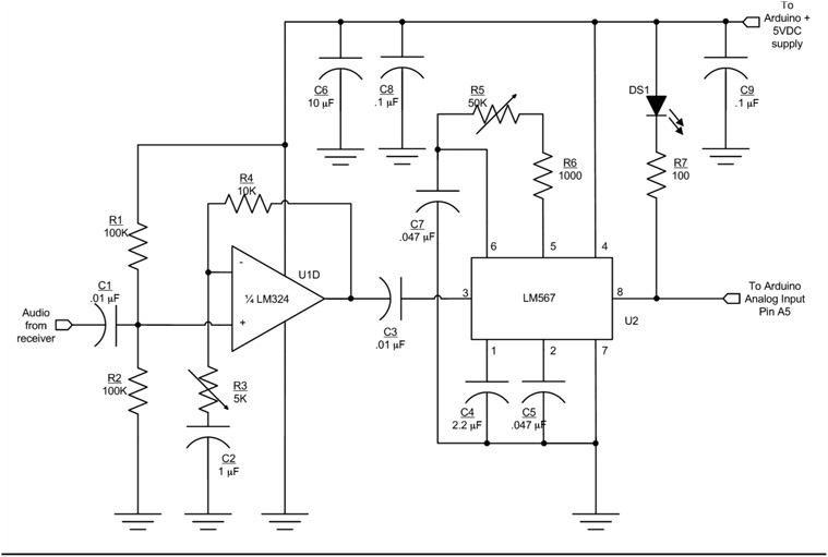
FIGURE 8-2 Signal preprocessing circuit.
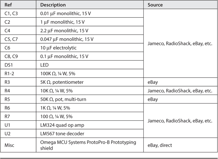
TABLE 8-1 Morse Decoder Parts List
The story, however, is just beginning because the software takes over the task of delivering a useful output from the preprocessed signal.
Signal Preprocessing Circuit Description
The circuit for the Morse code decoder consists of an amplifier stage to boost the incoming signal followed by a tone decoder (see the schematic in Figure 8-2). In this case, we are using an LM324 op amp for signal amplification and the LM567 tone decoder to further process the amplified signal. We added the gain stage (LM324 op amp) just in case there is not enough audio signal to drive the LM567.
The parts placement for the circuit shown in Figure 8-2 is presented in Figure 8-3.
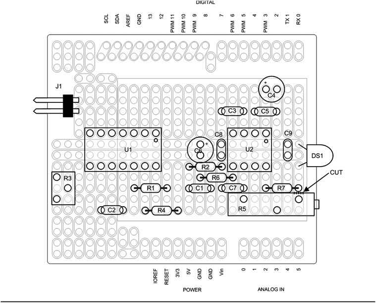
FIGURE 8-3 Decoder parts placement.
The amplifier uses one section of the LM324 quad op amp. It is designed as a non-inverting amplifier with adjustable gain. The LM324 is designed to operate off of a single supply; it is biased internally to provide “zero Volts out for zero Volts in.” This biasing arrangement is great for a DC amplifier (such as was used in Chapter 5 for the general purpose panel meter), but it does not work well for an audio amplifier. We would much rather have an audio amplifier with the idling output halfway between the positive and negative supply voltages (in this case 5 V and ground), or about 2.5 V. Resistors R201 and R202 provide the necessary input bias to set the idle output at approximately half the supply voltage. The actual output voltage varies depending on the tolerance of the resistors and the gain setting.
R203 and R204 set the gain for the op amp. C202 serves two purposes: 1) it provides a low frequency roll-off, and 2) prevents any DC offset on the inverting input from affecting the output. The formula for determining gain in a non-inverting configuration is:
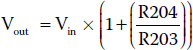
You can use the formula to adjust the gain to a different value if you wish. C201 and C203 are coupling capacitors that prevent any stray DC from the previous stage from affecting the next stage in the circuit.
The LM567 is a simple phase-locked-loop that is used as a tone decoder. C207, R205, and R206 set the center frequency of the decoder. We used a 10-turn pot for R205. While you can use a different part for R205, the 10-turn pot makes it a lot easier to set the center frequency. R205 is used to adjust the LM567 center frequency to be the same as the centered audio tone using the narrowest CW filter on your receiver. The bandwidth of the decoder is set by C205, the loop filter. C204 is the “output filter” and it is used to smooth the output to remove noise in the decoded input. An LED (CR201) is used as a tuning indicator. When a signal is properly tuned in, CR201 flashes in sync with the incoming Morse code audio. R207 is a current limiting resistor for CR201. The completed Morse decoder shield is shown in Figure 8-4.
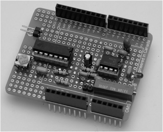
FIGURE 8-4 Assembled decoder shield.
Notes When Using the Decoder with the TEN-TEC Rebel
The Rebel presents a unique integration of a commercial product and “homebrew” add-ons. The Morse code decoder circuit can be built on shield to plug right into the Rebel. The Rebel utilizes a Digilent chipKIT Uno32 processor, which is an “Arduino-like” board. However, there are several things that are slightly different when using the Uno32 over any other Arduino.
While the Uno32 may look like an Arduino Uno or a Demilanove, you will notice that there are two rows of analog inputs and two rows of digital IO pins. Where the Arduino Uno and Demilanove have 6 analog inputs, the Uno32 has 12. Similarly, the Uno and Demilanove have 16 digital IO pins, the Uno32 has 30. When you build a shield for the Uno32, you must use the right kind of shield (one that supports two rows of pins for IO and analog inputs) and then the board must have some modifications made if you are to take advantage of the extra pins.
The Morse code decoder uses analog 6 (A6) from the Rebel for the input audio. The Rebel calls this pin the “Code Read” pin. It is a very low level audio signal that is tapped off before the final audio PA and volume control but after the AGC. This signal is about 40 mV, hence the need for a gain stage before the LM567 tone decoder. The decoded audio is sent back to the processor on pin analog 11 (A11). A11 is an unassigned analog input on the Rebel.
The typical Uno32 shield with two rows of pins has the adjacent pins connected together. Therefore it will be necessary to separate those pins. We prefer using a Dremel tool with a cutting disk, but an Xacto knife would do the trick as well. Unless you are planning on using other analog and digital pins on the Rebel, it should only be necessary to cut apart A0 and A6 as well as A5 and A11. You can then use the breakaway headers to cut off two single pins for A6 and A11. Use the Rebel as a guide to hold the pins as you solder them to the shield. Of course, we don’t need to remind you to make sure the power is disconnected from the Rebel before you use it to hold the header pins for soldering to the shield.
Of course, you can also use a prototyping shield that is made specifically for the chipKit Uno32. No cutting required! If you are building the decoder for different equipment, a regular Arduino shield works fine.
Decoder Software
There are probably dozens of workable algorithms that can be used to process the CW signal that comes into the Arduino. Some of these algorithms are like sledgehammers being used to craft a fine piece of jewelry. Indeed, some are sufficiently crude that they surely must degrade the performance of the decoder, both in terms of the code speed they can read and the reaction time for break-in keying. While we could spend a bucket load of time crafting our own solution, we chose to stand on the shoulders of others to cut down on the coding cycle. We drew upon the work of a number of other people.
One very interesting approach was developed by a Norwegian individual named Ragnar O. Aronsen. His web site http://raronoff.wordpress.com/2010/12/16/morse-endecoder/ provides an excellent description of how his software works. If you wish to experiment with his code, you can download his code at https://code.google.com/p/morse-endecoder/.
A key element in his approach to decoding the incoming CW is the use of a binary tree. While you may not be familiar with the term “binary tree,” you have probably used it yourself in various guessing games. Binary trees work for data that is arranged in an order that permits a binary search on the data. For example, suppose you are charged with guessing a number between 1 and 100 and, after each guess, you are told that your guess is too high or too low. You could just start with 1, increment by 1 after each guess until you reach the correct number. On a large group of random numbers, your average number of guesses should approach 50. Not good.
A more efficient way is to divide the list in half and make your first guess 50. If they tell you your guess is too low, you can immediately throw away half of the list (i.e., numbers 1 through 50) and concentrate on the numbers that remain. Because your first guess was too low, your next guess should be halfway up the numbers that remain, or 75. (If the guess of 50 was too high, you would halve the difference and guess 25 and you would discard all numbers from 50 through 100.) Note that after just two guesses, you have eliminated three-quarters of the numbers. You repeat this process until you zeroed in on the number. Using this approach you will know the number within six guesses which, on average, is about eight times faster than linear guessing. This is what is called a binary search: You divide the range in half each time, throwing out half of the remaining list on each guess.
Search a Binary Tree of ASCII Characters
In the Aronsen code, he arranges the Morse code characters in a manner similar to that seen in Figure 8-5.
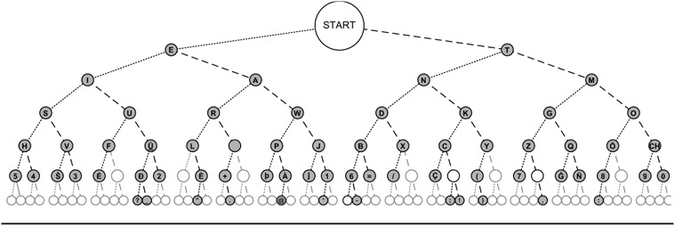
FIGURE 8-5 Morse code arranged as a binary tree. (Source: http://commons.wikimedia.org/wiki/File:Morse_code_tree3.png)
Just as you started the guessing game at the mid-range point, so does the search of a binary tree start at the midpoint. Let’s call each aspect of an incoming Morse code character an atom. In other words, an atom can be a dot or a dash, depending upon its duration. If the table has 128 characters in it, the pointer starts at the midpoint, or position 64, labeled Start in Figure 8-5. If the first atom is a dit, the pointer moves from Start halfway to the left, or position 32. If the first atom is a dah, the pointer moves halfway to the right, position 96. Therefore, the rule is dits move halfway left, dahs move halfway right.
If the first atom of a character read is a dit, the pointer moves midway to the left (i.e., position 32 = Start / 2 = 64 / 2) and reads the letter E. If the next atom equals the spacing for a letter, we know the character is complete and the Morse character is an E. However, if the next atom is a dah, then we move halfway to the right (48 = (64 – 32) / 2 + 32) and find the letter A. If, instead of a dah the next atom is a dit, we move halfway to the left again and find the letter I (16 = 32 / 2). Once again, if the next atom is a letter space, we either have an A or an I, depending upon which atom was actually read. You can see that six-level tree as shown in Figure 8-3 means that we can find any given letter in six comparisons or less. Binary trees using a binary search are a very efficient way of locating an individual element in a list of organized data.
Upon seeing this binary tree approach for character lookup, we immediately were interested in implementing Ragnar’s code. We figured it would be more than fast enough to keep up with any human code that might come across the airwaves. In fact, Ragnar has a video that shows two Arduinos; one receiving code and the other sending it, decoding successfully at over 300 words per minute (wpm)! Of course, the advantage is that the signal was not going out “over the airwaves” and the code being sent was perfect (i.e., 1:3 ratio) code. Still, that’s a pretty impressive speed. However, after some experimentation, we discovered that almost any table lookup is fast enough for human-generated code, even badly programmed examples.
Another algorithm we examined closely was by Budd Churchward, WB7FHC. We liked his approach because it is similar to the encoding used by Mark VandeWettering, K6HX, which we adapted to the PS2 keyer presented in Chapter 9. The actual coding scheme used by Budd is explained very clearly in a tutorial you can read at http://www.honorlevel.com/data/arduino/readcode/readCode.01.html.
In essence, each code character is encoded as a byte value where a start bit is binary 1 and the actual code sequence follows. Each dit is encoded as a 1 bit, and each dah as a 0 bit. Therefore, if you were going to send the letter A, which is dit-dah, the binary representation Budd uses becomes 00000110. Reading the byte from left to right, the first bit 1 digit is the start bit and is ignored, which leaves 10 as the remaining bit pattern. Because a dit is 1 and a dah is 0, the bit pattern is dit-dah, or the letter A.
Budd stores the alphabet in character form in the following array:
![]()
You binary aficionados know that binary 00000110 is decimal 6. Now, look at mySet[6] above and what do you find? Because C arrays start with element 0, mySet[6] is the letter A. What about the letter N, which is dah-dit, or using Budd’s encoding, 00000101 in binary is 5 in decimal. mySet[5] is the letter N. If you pick various elements in the array and work out the binary value for its index, you’ll find that the array contains the Morse alphabet using Budd’s encoding scheme. The ‘#’ characters in the array correspond to array indexes that do not contain a valid Morse character. Pretty slick! We also like it because any bit shifting we may need to do to extract letters is an extremely efficient operation on a μC.
Morse Decode Program
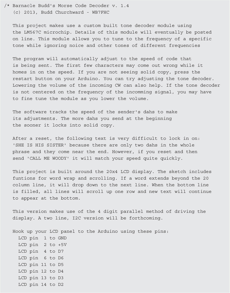
As we mentioned earlier, most of the Morse decode program is based on Budd Churchward’s code. Listing 8-1 presents the code for the Morse decoder.


)
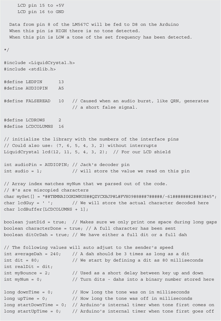
LISTING 8-1 The Morse decode code.
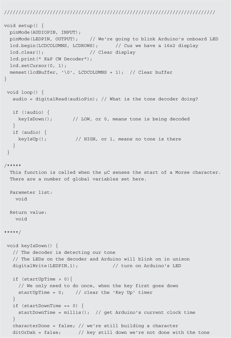
The code begins with the usual definitions for symbolic constants and working variables. The code that appears in the setup() function establishes the parameters for the LCD display and set the pin modes for the audio input and LED. We use the LED to verify that the code is in sync with the code being received.
In essence, the decoder is a state machine that is controlled by the audio input to the system. In loop(), the first thing that is done is to sample the audio pin for the presence or absence of an audio signal via a call to digitalRead(), assigning the value to audio. If there is no audio input, either there is no Morse signal or the signal is being decoded. This state is such that the function keyIsDown() is called. If there is a tone, we assume that a Morse character is being read, keyIsUp() is called. This seems like the logic is reversed from what it should be, but keep in mind that determining a dit or a dah depends upon the start and end times for a given atom. (Recall that an atom can be either a dit or a dah.) Either way, the duration of the audio signal is important in decoding the incoming character.
Consider a key down event. Because a single dit atom can be read multiple times during loop(), we need a way to know whether this is the continuation of an atom that has previously been sensed or if we are starting a new atom. We do this by reading the variable named startDownTime. If startDownTime is zero, we know we are at the start of an atom so we assign the millisecond count from a call to millis() into startDownTime. Because this is the start of a new character, we set myNum to 1. myNum is the variable we use to calculate the binary bit pattern used to index into the mySet[] character array mentioned earlier. Some working variables (characterDone and ditOrDah) are also set at this point. Program control now returns back to loop().
Once again, digitalRead() is called and its value assigned into audio. If no signal is detected, either we have the end of an atom or we are in a space of some sort (e.g., between letters, words, or just a plain pause). If startUpTime is zero, we assign the current millisecond count into it. We then calculate the amount of time that has transpired since startUpTime was read and assign it into upTime. A very short value for upTime would take place if we just read millis() or if there was a short signal burst, like static. In either case, we simply return to loop(). However, if the value of upTime is fairly long, we remain in the keyIsUp() function for further processing.
Farnsworth Timing
A good portion of the remainder of the keyIsUp() function is an attempt to cope with Farnsworth timing. Simply stated, Farnsworth timing is recognition of the fact that people who can copy Morse code well do so by listening to the rhythm of the characters rather than individual dits and dahs. Because a rhythm is more difficult to detect at slower speeds, Farnsworth timing speeds up the characters being sent, but increases the spacing between characters. For example, if the code speed is to be 13 wpm, Farnsworth timing might send the Morse characters at 18 wpm, but adds additional time between characters so that the average speed is 13 wpm. (You can find an ARRL paper on the topic at http://www.arrl.org/files/file/Technology/x9004008.pdf.)
Clearly, this messes up the traditional timing characteristics between letters and words, which means our attempt to decode a signal using Farnsworth timing is going to be difficult at best. The ARRL code practice sessions, for example, use Farnsworth timing at speeds less than 18 wpm, but uses conventional timing on speeds of 18 wpm or greater. The ARRL feels that speeds at and above 18 wpm have sufficient speeds to sense the rhythm of the characters being sent. However, trying to write code that copes with this variance isn’t easy. We used the ARRL Morse audio MP3 files to try to process Farnsworth timing as well as regular timing. Quite honestly, we don’t feel we have a good solution yet. Our efforts are a starting point, not an end point. If you come up with a solution, we sure hope you’ll share it with the rest of us.
If upTime is greater than three times a dit spacing, we assume that we have just finished “reading” a space and printSpace() is called. If startDownTime is nonzero, we know that an atom (at least) has just been finished. downTime then becomes the difference between the current value of millis() and startDownTime. If we don’t yet know whether we are processing a dit or a dah, a call to shiftBits() is done. Based on the value of downTime, we can determine whether we need to increment myNum (which becomes the index value into the mySet[] character array) or not. Recall that a dit increments myNum while a dah does not. The shiftBits() function also tracks the average time for dahs in an attempt to detect a change in sending speed.
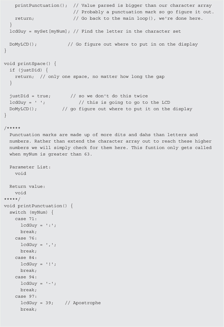
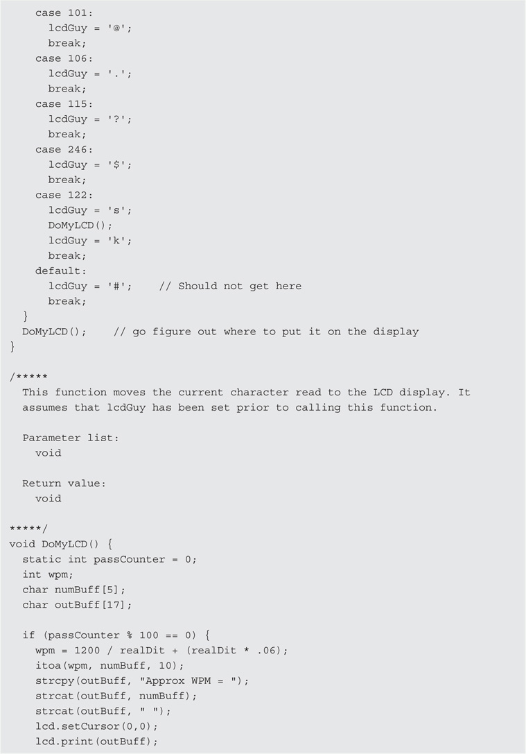
If upTime is greater than what a dah should be, we assume that we are between characters and we can display the character via a call to printCharacter(). In printCharacter(), we check to see if myNum is greater than 63, which is the largest index permitted in the mySet[] character array. If it is, special case processing is performed by a call to printPunctuation(). Otherwise, the character is displayed on the LCD display by a call to DoMyLCD().
The DoMyLCD() also attempts to display an approximation of the current sending speed. Again, this is at best an approximation and Farnsworth speeds make it even more so. Still, perhaps a hint of the current speed is better than nothing. Also, note the statement:
memcpy(lcdBuffer, &lcdBuffer[1], LCDCOLUMNS - 1);
Often you will see code where someone is copying a sequence of characters from one array to another using a for loop. The memcpy() function is a considerably faster way to do that. The first parameter is the destination array, the second parameter is the source for the copy, and the third parameter is the number of bytes to copy. Note what our memcpy() does. Our source is everything from the second element of the array onward, but it copies it back onto itself starting at the first element. If you wrap your head around this, the result is that we are “scrolling” the contents of the array on the LCD display because we update the last character on the display with the character that we just parsed.
Another mem*() function worth knowing is memset(), which can be used to set a section of memory, like an array, to a single value. For example, the statement:
memset(buffer, 32, sizeof(buffer));
sets all of the valid bytes in buffer to a space character. (The ASCII value for a space is 32.) The first parameter is the area of memory to use, the second is the value to use for each byte in that memory space, and the final parameter is the number of bytes to process. Note how using the sizeof operator makes the idiom for the third parameter portable for any data array on any system. Using the idiom would work, for example, whether your host system uses 2- or 4-byte ints.
Once the call to DoMyLCD() finishes, control ultimately returns to loop() and the process begins again.
Conclusion
This chapter presents a CW decoder that preprocesses the signal before decoding it. Using W1AW code practice MP3 files for testing, we were able to copy speeds of around 35–40 wpm. The software is not terribly complex, but there are so many variations in sending CW that it is difficult to get a 100% decode message. Farnsworth timing complicates things, but even that could be handled if everyone had a “perfect fist.” Alas, that is not the case. Some hams have a rhythm that is almost lyrical, why others make you feel like you’re listening to a buzz saw. Still, given its relatively low cost, it is easy to build the shield and experiment with the software. This is one project where some innovative change to the software could bring about significant improvement in the results. Give it a try and let us all know how you fared.