
7.2 Design Methodologies
This section considers the complete design methodology—a design process—for embedded computing systems. We will start with the rationale for design methodologies, then look at several different methodologies.
7.2.1 Why Design Methodologies?
Process is important because without it, we can’t reliably deliver the products we want to create. Thinking about the sequence of steps necessary to build something may seem superfluous. But the fact is that everyone has their own design process, even if they don’t articulate it. If you are designing embedded systems in your basement by yourself, having your own work habits is fine. But when several people work together on a project, they need to agree on who will do things and how they will get done. Being explicit about process is important when people work together. Therefore, because many embedded computing systems are too complex to be designed and built by one person, we have to think about design processes.
Product metrics
The obvious goal of a design process is to create a product that does something useful. Typical specifications for a product will include functionality (e.g., personal digital assistant), manufacturing cost (must have a retail price below $200), performance (must power up within 3 seconds), power consumption (must run for 12 hours on two AA batteries), or other properties. Of course, a design process has several important goals beyond function, performance, and power:
• Time-to-market. Customers always want new features. The product that comes out first can win the market, even setting customer preferences for future generations of the product. The profitable market life for some products is three to six months—if you are three months late, you will never make money. In some categories, the competition is against the calendar, not just competitors. Calculators, for example, are disproportionately sold just before school starts in the fall. If you miss your market window, you have to wait a year for another sales season.
• Design cost. Many consumer products are very cost sensitive. Industrial buyers are also increasingly concerned about cost. The costs of designing the system are distinct from manufacturing cost—the cost of engineers’ salaries, computers used in design, and so on must be spread across the units sold. In some cases, only one or a few copies of an embedded system may be built, so design costs can dominate manufacturing costs. Design costs can also be important for high-volume consumer devices when time-to-market pressures cause teams to swell in size.
• Quality. Customers not only want their products fast and cheap, they also want them to be right. A design methodology that cranks out shoddy products will soon be forced out of the marketplace. Correctness, reliability, and usability must be explicitly addressed from the beginning of the design job to obtain a high-quality product at the end.
Processes evolve over time. They change due to external and internal forces. Customers may change, requirements change, products change, and available components change. Internally, people learn how to do things better, people move on to other projects and others come in, and companies are bought and sold to merge and shape corporate cultures.
Software engineers have spent a great deal of time thinking about software design processes. Much of this thinking has been motivated by mainframe software such as databases. But embedded applications have also inspired some important thinking about software design processes.
A good methodology is critical to building systems that work properly. Delivering buggy systems to customers always causes dissatisfaction. But in some applications, such as medical and automotive systems, bugs create serious safety problems that can endanger the lives of users. We discuss quality in more detail in Section 7.6. As an introduction, Example 7.1 describes problems that led to the loss of an unmanned Martian space probe.
Example 7.1 Loss of the Mars Climate Observer
In September 1999, the Mars Climate Observer, an unmanned U.S. spacecraft designed to study Mars, was lost—it most likely exploded as it heated up in the atmosphere of Mars after approaching the planet too closely. The spacecraft came too close to Mars because of a series of problems, according to an analysis by IEEE Spectrum and contributing editor James Oberg [Obe99]. From an embedded systems perspective, the first problem is best classified as a requirements problem. The contractors who built the spacecraft at Lockheed Martin calculated values for flight controllers at the Jet Propulsion Laboratory (JPL). JPL did not specify the physical units to be used, but they expected them to be in newtons. The Lockheed Martin engineers returned values in units of pound force. This discrepancy resulted in trajectory adjustments being 4.45 times larger than they should have been. The error was not caught by a software configuration process nor was it caught by manual inspections. Although there were concerns about the spacecraft’s trajectory, errors in the calculation of the spacecraft’s position were not caught in time.
7.2.2 Design Flows
A design flow is a sequence of steps to be followed during a design. Some of the steps can be performed by tools, such as compilers or computer-aided design (CAD) systems; other steps can be performed by hand. In this section we look at the basic characteristics of design flows.
Waterfall model
Figure 7.1 shows the waterfall model introduced by Royce [Dav90], the first model proposed for the software development process. The waterfall development model consists of five major phases: requirements analysis determines the basic characteristics of the system; architecture design decomposes the functionality into major components; coding implements the pieces and integrates them; testing uncovers bugs; and maintenance entails deployment in the field, bug fixes, and upgrades. The waterfall model gets its name from the largely one-way flow of work and information from higher levels of abstraction to more detailed design steps (with a limited amount of feedback to the next-higher level of abstraction). Although top-down design is ideal because it implies good foreknowledge of the implementation during early design phases, most designs are clearly not quite so top down. Most design projects entail experimentation and changes that require bottom-up feedback. As a result, the waterfall model is today cited as an unrealistic design process. However, it is important to know what the waterfall model is to be able to understand how others are reacting against it.

Figure 7.1 The waterfall model of software development.
Spiral model
Figure 7.2 illustrates an alternative model of software development, called the spiral model[Boe87]. While the waterfall model assumes that the system is built once in its entirety, the spiral model assumes that several versions of the system will be built. Early systems will be simple mock-ups constructed to aid designers’ intuition and to build experience with the system. As design progresses, more complex systems will be constructed. At each level of design, the designers go through requirements, construction, and testing phases. At later stages when more complete versions of the system are constructed, each phase requires more work, widening the design spiral. This successive refinement approach helps the designers understand the system they are working on through a series of design cycles. The first cycles at the top of the spiral are very small and short, while the final cycles at the spiral’s bottom add detail learned from the earlier cycles of the spiral. The spiral model is more realistic than the waterfall model because multiple iterations are often necessary to add enough detail to complete a design. However, a spiral methodology with too many spirals may take too long when design time is a major requirement.
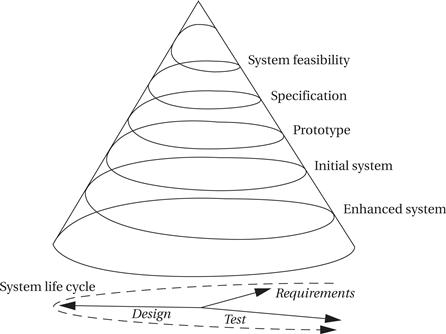
Figure 7.2 The spiral model of software design.
Successive refinement
Figure 7.3 shows a successive refinement design methodology. In this approach, the system is built several times. A first system is used as a rough prototype, and successive models of the system are further refined. This methodology makes sense when you are relatively unfamiliar with the application domain for which you are building the system. Refining the system by building several increasingly complex systems allows you to test out architecture and design techniques. The various iterations may also be only partially completed; for example, continuing an initial system only through the detailed design phase may teach you enough to help you avoid many mistakes in a second design iteration that is carried through to completion.
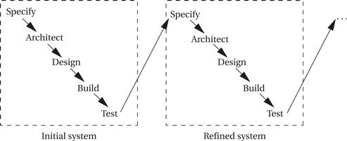
Figure 7.3 A successive refinement development model.
Embedded computing systems often involve the design of hardware as well as software. Even if you aren’t designing a board, you may be selecting boards and plugging together multiple hardware components as well as writing code. Figure 7.4 shows a design methodology for a combined hardware/software project. Front-end activities such as specification and architecture simultaneously consider hardware and software aspects. Similarly, back-end integration and testing consider the entire system. In the middle, however, development of hardware and software components can go on relatively independently—while testing of one will require stubs of the other, most of the hardware and software work can proceed relatively independently.
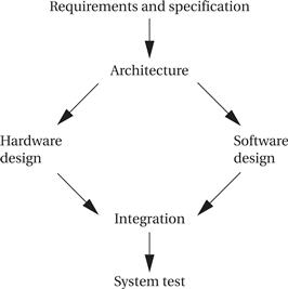
Figure 7.4 A simple hardware/software design methodology.
Hierarchical design flows
In fact, many complex embedded systems are themselves built of smaller designs. The complete system may require the design of significant software components, application-specific integrated circuits (ASICs), and so on, and these in turn may be built from smaller components that need to be designed. The design flow follows the levels of abstraction in the system, from complete system design flows at the most abstract to design flows for individual components. The design flow for these complex systems resembles the flow shown in Figure 7.5. The implementation phase of a flow is itself a complete flow from specification through testing. In such a large project, each flow will probably be handled by separate people or teams. The teams must rely on each other’s results. The component teams take their requirements from the team handling the next higher level of abstraction, and the higher-level team relies on the quality of design and testing performed by the component team. Good communication is vital in such large projects.
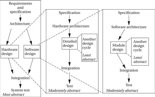
Figure 7.5 A hierarchical design flow for an embedded system.
Concurrent engineering
When designing a large system along with many people, it is easy to lose track of the complete design flow and have each designer take a narrow view of his or her role in the design flow. Concurrent engineering attempts to take a broader approach and optimize the total flow. Reduced design time is an important goal for concurrent engineering, but it can help with any aspect of the design that cuts across the design flow, such as reliability, performance, power consumption, and so on. It tries to eliminate “over-the-wall” design steps, in which one designer performs an isolated task and then throws the result over the wall to the next designer, with little interaction between the two. In particular, reaping the most benefits from concurrent engineering usually requires eliminating the wall between design and manufacturing. Concurrent engineering efforts are comprised of the elements described below.
• Cross-functional teams include members from various disciplines involved in the process, including manufacturing, hardware and software design, marketing, and so forth.
• Concurrent product realization process activities are at the heart of concurrent engineering. Doing several things at once, such as designing various subsystems simultaneously, is critical to reducing design time.
• Incremental information sharing and use helps minimize the chance that concurrent product realization will lead to surprises. As soon as new information becomes available, it is shared and integrated into the design. Cross-functional teams are important to the effective sharing of information in a timely fashion.
• Integrated project management ensures that someone is responsible for the entire project, and that responsibility is not abdicated once one aspect of the work is done.
• Early and continual supplier involvement helps make the best use of suppliers’ capabilities.
• Early and continual customer focus helps ensure that the product best meets customers’ needs. Example 7.2 describes the experiences of a telephone system design organization with concurrent engineering.
Example 7.2 Concurrent Engineering Applied to Telephone Systems
A group at AT&T applied concurrent engineering to the design of PBXs (telephone switching systems) [Gat94]. The company had a large existing organization and methodology for designing PBXs; their goal was to re-engineer their process to reduce design time and make other improvements to the end product. They used the seven-step process described below.
1. Benchmarking. They compared themselves to competitors and found that it took them 30% longer to introduce a new product than their best competitors. Based on this study, they decided to shoot for a 40% reduction in design time.
2. Breakthrough improvement. Next, they identified the factors that would influence their effort. Three major factors were identified: increased partnership between design and manufacturing; continued existence of the basic organization of design labs and manufacturing; and support of managers at least two levels above the working level. As a result, three groups were established to help manage the effort. A steering committee was formed by midlevel managers to provide feedback on the project. A project office was formed by an engineering manager and an operations analyst from the AT&T internal consulting organization. Finally, a core team of engineers and analysts was formed to make things happen.
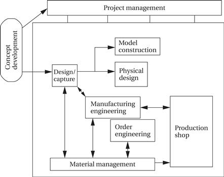
3. Characterization of the current process. The core team built flowcharts and used other techniques to understand the current product development process. The existing design and manufacturing process resembled this process:

The core team identified several root causes of delays that had to be remedied. First, too many design and manufacturing tasks were performed sequentially. Second, groups tended to focus on intermediate milestones related to their narrow job descriptions, rather than trying to take into account the effects of their decisions on other aspects of the development process. Third, too much time was spent waiting in queues—jobs were handed off from one person to another very frequently. In many cases, the recipient of a set of jobs didn’t know how to best prioritize the incoming tasks. Fixing this problem was deemed to be fundamentally a managerial problem, not a technical one. Finally, the team found that too many groups had their own design databases, creating redundant data that had to be maintained and synchronized.
4. Create the target process. Based on its studies, the core team created a model for the new development process:
5. Verify the new process. The team undertook a pilot product development project to test the new process. The process was found to be basically sound. Some challenges were identified; for example, in the sequential project the design of circuit boards took longer than that of the mechanical enclosures, while in the new process the enclosures ended up taking longer, pointing out the need to start designing them earlier.
6. Implement across the product line. After the pilot project, the new methodology was rolled out across the product lines. This activity required training of personnel, documentation of the new standards and procedures, and improvements to information systems.
7. Measure results and improve. The performance of the new design flow was measured. The team found that product development time had been reduced from 18–30 months to 11 months.