Stepper Library
The servo motor is an easy motor to hook up and does what it does with ease, but what if we want that same kind of positional accuracy in a motor that can spin the full 360? For that, we need to use a stepper motor, which is a type of motor that rather than spinning continuously, rotates in a specific number of degrees or steps. The amount of rotation per step is dependent on the individual stepper; ours has a rotation of 1.8° per step while others can range from as little as 0.9° per step to as much as 30° per step or more.
To control a stepper motor, the internal coils of the motor need to be individually energized in a particular sequence, dependent on the type of stepper motor, either unipolar or bipolar. Unipolar steppers often have five or six wires with a common ground connection and the current flows through each coil in only one direction. Bipolar steppers, on the other hand, only have four wires with no common connection and the current flows through each coil in both directions.
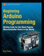
While there are a multitude of drivers available, we are going to use one of two simple chips that only cost a couple dollars each and require no external components to get going. To control a unipolar stepper motor, we will use the ULN2003 Darlington transistor array. A Darlington array is a series of transistor pairs, where a small transistor drives a second transistor to increase its capacity, all on a single integrated circuit or IC. Four individual transistors would have the same effect, although not as convenient. The ULN2003 actually has seven transistor pairs on the chip, although we will only use four of them. By turning each transistor on in order, we can power each coil of the motor causing the motor to spin.
For bipolar stepper motors, we will use the SN754410 dual H-bridge. An H-bridge is a special arrangement of transistors on a chip that is capable of reversing the direction of the current between two pins. When used on standard DC motors, this would change the direction that the motor spins. In the case of a bipolar stepper, alternating the direction of current flow on each coil will create a step causing the motor to turn in a direction determined by the sequence.
Because every stepper is a little different, we will provide two schematics and illustrations for the two types of motor: Figures 9-8 and 9-9 for unipolar and 9-10 and 9-11 for bipolar. Pick the circuit that matches your motor type, being careful to wire the stepper motor coils as shown in the schematic. We have also used a motor that can safely operate from the Arduino board’s +5v output. If you are using a motor with a different voltage or higher current requirement, then you should connect an external power supply to the +V Motor pins instead of +5v. For more information on determining the electrical characteristics of stepper motors, you might want to check out the following links:
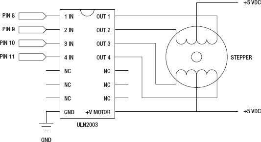
Figure 9-8. Unipolar Stepper schematic

Figure 9-9. Unipolar Stepper illustration
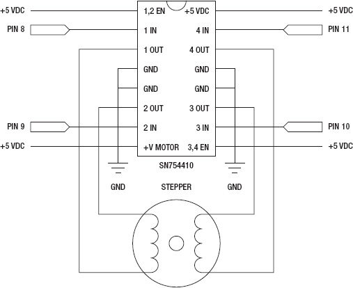
Figure 9-10. Bipolar Stepper schematic
Figure 9-11. Bipolar Stepper illustration
Example Code: 60-Second Sweep
Have you ever wanted a clock that moves backwards? For our example source code found in Listing 9-6, we are going to create a pseudo time-keeping device that is eternally trapped in a 60-second loop. The stepper will move in a full 360° arc in about a minute. At the end of its arc, it will switch direction and spin the other way. Because our stepper moves in 1.8° steps, it’s not entirely possible to have the most exacting of timepieces here, but it’s close enough. Because of this, each second the stepper should move 3.33 steps, which it can’t do. So we fudge the delay a little bit with a delay between steps of 909 milliseconds instead of 1 second. Because of how the two different circuits shown in the figures are designed, the single sketch provided will control either type of motor.
Listing 9-6. 60-Second Sweep Source Code
#include <Stepper.h>


const int steps = 200;

Stepper stepper(steps, 8, 9, 10, 11);


int stepDirection = 3;

int counter = 0;


void setup() {

  stepper.setSpeed(30);

}


void loop() {

  stepper.step(stepDirection);

  delay(909);

  counter+=3;

  if (counter > steps) {

    counter = 0;

    if (stepDirection == 3) stepDirection = -3;

    else stepDirection = 3;

  }

}
With our simple code in place rotating our stepper motor back and forth, let’s explore the Stepper functions in greater depth.
Stepper
To create a new instance of the Stepper library, we use one of the following two syntaxes:
Stepper name(steps, pin 1, pin 2)

Stepper name(steps, pin1, pin 2, pin 3, pin4)
The syntax we use depends on whether we are using two pins or four pins to control the stepper drivers. To make our wiring a little easier and the code work on both drivers, we chose to use four pins—easier to wire at the cost of a pair of digital pins. In our example code, we created the following Stepper instance:
Our instance is named stepper although we could use almost anything for the name. The first parameter is the number of steps that our stepper motor is capable of in one full rotation. For our stepper, it has 1.8° steps, meaning that it would take 200 steps to complete a single rotation. A 7.2° step stepper motor would likewise have 360° / 7.2° or 50 total steps per revolution. In our earlier code, we declared the number of steps for our motor as the constant variable steps that we will use later in our code. The next four parameters, pins1–4, are the pin numbers connected to the drivers. Refer to the schematic for which pins go where.
setSpeed()
With our instance created, we need to set the rotational speed for our motor. The syntax for this function only has one parameter, as follows:
name.setSpeed(rpm)
The speed for our motor is set as rotations per minute. This value determines how fast the stepper moves from step to step and will naturally vary for each stepper motor. Setting this value too high for your motor may cause skipped steps or intermittent operation. Choose a speed appropriate for your application and/or motor.
Remember that the setSpeed() function does not actually move the motor—it only establishes the speed of the motor when our next function is called.
step()
The step() function is what actually makes the motor move. The syntax is simple, but there are some things we need to keep in mind.
name.step(steps)
The one parameter to pass to this function is the number of steps that we want to move the stepper motor. For example, with a 1.8° step motor, one step equals a 1.8° movement. Setting the number of steps to 50 will turn the motor 90° clockwise on our 200-step motor, or a quarter of a revolution, where -50 will turn the motor 90° counterclockwise. As you see, a positive integer will create a movement in one direction while a negative value sends it in the reverse direction.
Unlike something similar to the analogWrite() function, which you set and forget, step() will prevent the Arduino from doing anything else until it has completed its full move. This is not that big of a deal if we step the motor in small increments each time we call the step() function, but it quickly adds up. As a practical example, if we set the RPM speed to 10 RPM, our 200-step motor would take 6 seconds to complete 200 steps. In other words, if we used the statement stepper.step(200) then that would be 6 seconds that we will not be able to read inputs, communicate with other devices, or anything else. Instead it might be better to complete large rotations with a loop statement like the following code fragment:
for (int i=0; i<200; i++) {

  stepper.step(1);

  if (digitalRead(2) == HIGH) break;

}
In this example, we are incrementing the stepper motor 200 times in single-step increments to complete one revolution. Instead of calling a single 200-step movement by using a for loop, each individual step will only take 30 milliseconds and in between each step, we can, for example, check the status of a digital input pin and exit the loop using the break statement if a condition has been met.
With all of the Stepper library functions out of the way, let’s look at one more sketch in Listing 9-7 before we move on to our next and final library for this chapter. This sketch demonstrates one way to map the values from an analog sensor to the movement of the stepper motor. A potentiometer with a giant knob on it is a good choice, or maybe better yet an accelerometer that controls the movement of the stepper through the tilt of its axes, although any analog input would work as well. Using the map() function, we can take an analog reading and map it to the total number of steps to indicate the level of the analog input—a full reading of 1024 will turn the stepper one full revolution.
Listing 9-7. Analog Sensor to Stepper Source Code
#include <Stepper.h>


const int steps = 200;

Stepper stepper(steps, 8, 9, 10, 11);

int previous, val;


void setup() {

  stepper.setSpeed(30);

}


void loop() {

  val = map(analogRead(0), 0, 1024, 0, steps);

  stepper.step(val - previous);

  previous = val;

  delay(20);

}
Now that we have used libraries to display text on an LCD as well as making things move with two different kinds of motors, let’s take a look at how we can use libraries to store and retrieve information.