Common Components
While there are so many different electronic components, to discuss them all would fill a book larger than this one, so we are going to only look at a few of the very common components here. The idea is to get a sense of what these components look like and generally what kinds of things they do. That way, when you see them discussed or drawn up in a schematic, you'll have an idea of what you're looking at.
Resistors
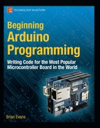
A resistor limits, or resists, the flow of electricity. They are often useful in a circuit that would not ordinarily place much resistance on the total load, like our LED. In this way, the resistor uses up the current by producing a small amount of heat. Fixed resistors have two wires, have no polarity (so they can be placed in a circuit in any direction), and are rated in ohms, the measurement of resistance, and watts, an indication of the amount of heat the resistor can take. Fixed resistors are marked with either a series of colored bands or other printed markings that determine the resistor's value. Figure 12-3 shows many different kinds of resistors.
In addition to resistors of the various types and sizes shown ranging from one-sixteenth of a watt to a massive 25-watt aluminum resistor, this image also shows several types of variable resistors. These resistors change their resistance depending on what kind of resistor they are. For example, a photoresistor or photocell will change its resistance depending on how light or dark it is, or how much or how little light hits the resistor. A thermistor changes resistance based on its temperature. A force sensitive resistor will respond to the amount of pressure or force applied to it. A special kind of resistor called a potentiometer will change resistance based on the position of a knob or slider.
We will use resistors for all manner of things, from limiting the current to other devices, reducing the voltage in a circuit, to measuring the change of variable resistors.
Capacitors
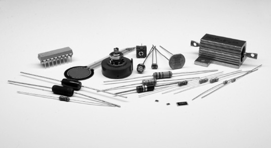
A capacitor will store an electrical charge when current is flowing into it only to release this charge when the current has been removed. Capacitors come in many different shapes and sizes, as shown in Figure 12-4, and are made from many different materials, but they all pretty much do the same thing. Their amount of capacitance is rated in a ridiculously large unit called a farad, although our capacitors will be a lot smaller than this, ranging from microfarads (μF) or a millionth of a farad, nanofarads (nF) a billionth of a farad, and picofarads (pF) a trillionth of a farad. These are small values indeed.
Inside a capacitor are two, parallel plates of conductive material separated by an insulating dialectic material. Common materials include an electrolytic oil, tantalum, ceramic, mica, and polyester. Some capacitors, like the electrolytic and tantalum capacitors, are polarized while others are not. Some circuits require one or the other, so pay attention to this as placing a polarized capacitor in a circuit the wrong way around might cause it to explode and damage other components.
We will often use capacitors to filter electronic signals, smoothing out any dips in the level of current caused by heavy or “noisy” loads. They are a necessary part of voltage regulation circuits and circuits that use motors to keep things running smoothly.
Diodes
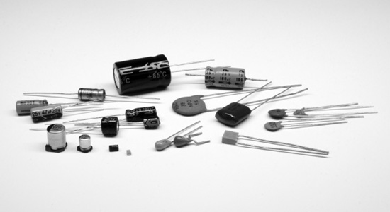
Diodes are devices that will only allow the current to flow through a circuit in one direction. By necessity, diodes are polarized, meaning that they can only go into a circuit one way. The diode will only conduct electricity when the side called the anode (+) is more positive than the side called the cathode (-). The cathode in a standard diode is usually marked with a line. If current attempts to enter the diode the wrong way, it will be blocked and will not pass through. Figure 12-5 shows a selection of diodes.
There are generally two types of diodes that we will most often use. The first is a general purpose rectifier diode, such as the 1N4001. This is used for applications where we need to protect our circuit from reverse voltages that can be caused by inductive loads such as motors, solenoids, or relays.
Arguably the most common diode is the light-emitting diode that we have used many times throughout the book already. LEDs are fairly popular with the microcontroller crowd because they are so simple to connect and require small amounts of power to run. These diodes will emit light when electricity passes through them. The anode or positive (+) pin is usually the longer pin, while the cathode or negative (−) pin is the shorter one. LEDs come in many shapes, sizes, and colors, from 10mm to 3mm; miniature surface mount to large multi-watt LEDs; as well as seven-segment and alphanumeric displays for displaying numbers and letters.
Transistors
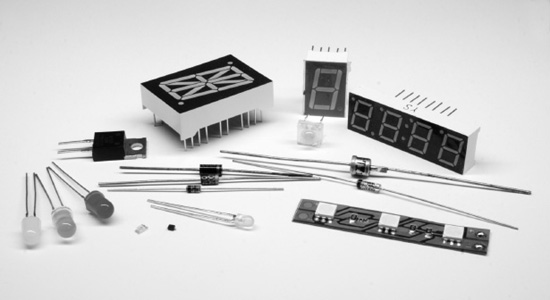
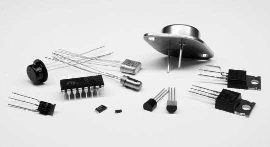
Transistors can be used just like an electrical switch. A small amount of current supplied to one pin of the transistor can switch a much greater load connected to the other pins. A bipolar transistor has three pins or wires that include the base, collector, and emitter. Figure 12-6 shows a few of the different packages available for transistors.
There are two types of transistors that we are mostly concerned with. The NPN transistor, such as the 2N3904, is capable of sinking current in a circuit, allowing for current to flow from the collector pin to the emitter pin whenever current is applied to the base pin. Occasionally, we will need to use a PNP transistor, like the 2N3906, which reverses the direction of the NPN, sourcing current rather than sinking it, allowing for current to flow from the emitter pin to the collector pin whenever current is applied to the base pin. The concepts of sourcing and sinking were explained more thoroughly in Chapter 5, but Figure 12-7 provides two example schematics for how this works with NPN and PNP bipolar transistors.

Figure 12-7. NPN and PNP bipolar transistors
We will get to reading schematics shortly, but even so, hopefully, these two schematics will illustrate the differences of the NPN and PNP transistors. We use the NPN transistor, like in the schematic on the left, to switch a load on the low side or negative side of the load. The PNP, on the other hand, like in the schematic on the right, is used to switch the high side or positive side of the load.
Another kind of transistor is the Metal Oxide Field Effect Transistor or MOSFET. MOSFETs, such as the IRF540, are available in N-channel and P-channel varieties, similar to NPN and PNP transistors. Unlike transistors though, MOSFETs are capable of handling larger currents and switch faster than our run-of-the-mill transistors. They are best used for large motors, high-wattage LEDs, heaters, or similar applications.
Switches
Switches are the human-operable, mechanical version of transistors. Their job is to interrupt or allow current to flow through a circuit. They do this with metal contacts inside the switch that either close or open when the switch is activated. There are many different kinds of mechanical switches, including momentary pushbuttons, slide switches, lever switches, reed switches, tilt switches, toggle switches, and even relays are a kind of mechanical switch. Many of these are shown in Figure 12-8.

Figure 12-8. Switches
The contacts of a switch are either normally open, N.O., or normally closed, N.C. So for example, a circuit with a normally open momentary pushbutton with two contacts will be open until the button is pressed closing the circuit. When the button is released again, the circuit is once again open. A lever switch with three contacts might have one pin labeled N.O., another N.C., and a third C. for common. When a circuit is connected to the N.O. and C. contacts, the circuit will be normally open and closed when the switch is activated. On the other hand, if the circuit were connected to the N.C. and C. contacts, the circuit would remain closed until the switch is activated, when it would open the circuit.
In addition to momentary and lever switches, slide switches or toggle switches stay in whatever position they were last left in. Slide and toggle switches are just like your vanilla, household light switch. Tilt switches, like we used earlier in the book, have a rolling ball inside that close or open the contacts depending on the angle of the switch. Reed switches have a pair of thin metal contacts inside a glass container that will close when a magnet passes near. These are often seen in alarm systems to alert when a window or door has been opened.
Relays have also been included here with other mechanical switches. The relay is a switch that is activated by a magnetic coil. When the coil is given an electric current, it closes the nearby contacts. Where transistors are only good for switching DC voltages, some relays can switch much higher AC voltages, although these relays will often need a transistor to power the larger magnetic coil to activate the switch. Many relays will also have multiple N.O. and N.C. positions available to hook up many different things.
Motors
Motors are included here because they are another common mechanical component used in many of our projects. They will either create radial motion, what we might typically associate with a motor, as well as linear motion using solenoids or other devices. Figure 12-9 shows a few of the many different types of motors available.

Figure 12-9. Motors
These are all DC-type motors. Motors that run on AC are as plentiful, but are also a bit more difficult to interface with microcontrollers. Radial DC motors are offered with or without built-in gearboxes.
Those motors with built-in gear boxes are called gearheads and generally run at much slower speeds, but increase the total available torque that the motor can provide. Solenoids are a type of motor that causes a shaft to contract or expand, creating linear movement when electricity is applied.
Different types of motors will have different types of characteristics. The ratings that we should be most concerned with are the motor's voltage and stall current. The rated voltage of a motor is for peak efficiency, although we can generally power a motor with a little more or less than it is rated for. The motor's stall current is the amount of amps the motor will pull when some force has caused the motor to stop moving. While the motor will generally run well below its stall current rating, our available power and switching mechanisms need to be rated for the greater stall current with a little room to spare to be on the safe side.
Radial motors are often also rated in revolutions per minute or RPM that tell us how fast the motor will spin. The speed of the motor is not as important for stepper or servo motors, which are more concerned with the positional accuracy, specified in degrees per step and total steps per revolution. Motors will also usually be rated for its pulling force or torque. This is measured by the amount of force the motor can apply at a given distance from the center of the motor's shaft. This rating is far from standard with measurements in oz/in, or ounces per inch; lb/ft, or pounds per foot; g/cm, or grams per centimeter; and even N/cm, for newtons per centimeter.
While we could continue to list category after category of components, we should probably stop here and talk about how we can use these components in our prototypes.