Reading Schematics
Let's revisit our basic circuit that we discussed earlier in this chapter from Figure 12-1, drawing it up in a type of diagram shown in Figure 12-10.

Figure 12-10. Basic circuit schematic
This drawing, an exact representation of the gadget in Figure 12-1, is a fairly standard wiring diagram called a schematic. We've been using them throughout this book, but you might want to know a little more about how they work. Schematics are a bit pictographic, like something out of the caves of Lascaux, but it shows us clearly how the circuit described earlier is connected. Once we know what the somewhat standardized symbols mean, in that a squiggle in a circle is a lamp, a bunch of long and short parallel lines is a battery, and a switch kind of looks like a broken line, then we can follow along with the drawing, connecting one component to another just as the lines in the schematic connect components together.
To make things easier in this book, all of our schematics have had an accompanying illustration to provide a little better sense of the completed prototyped circuit, but once you get a feeling for what all those symbols mean then it's not really all that bad. Being able to read a schematic also makes it a lot easier to wire things up. Some of the more common schematic symbols are shown in Figure 12-11.
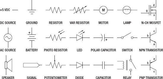
Figure 12-11. Common schematic symbols
While these symbols are somewhat abstract, they are also loosely based on reality. Some resistors are made by winding a long length of wire very tightly in a small package, capacitors have two plates that are sometimes separated by air, and diodes let electricity pass in one direction but block it in the other. By reading these symbols, we can use these schematics to build prototype circuits on our breadboards.