
4 Video Standards and Formats
We tend to like to draw postproduction workflows as flowcharts, boxes, and arrows to represent stages and resources and tasks. We imagine our project flowing through these paths and processes, but what exactly is this stuff? For that matter, what do the lines and arrows and boxes really represent in terms of real-world equipment? While we are at it, what about all those acronyms and numbers: DV-25, XLR, BNC, 720p?
Let's put it this way—video technology and the associated terminology are complex.
Unless you like to read manuals as bedtime reading or can quote format bandwidth down to the megabit, you're probably confused about a lot of things. This chapter is by no means the end-all of technical literature. It is a quick resource for some common questions and answers about formats, connectors, and other video and audio terminology.
To really develop a postproduction workflow, it is necessary to understand some principles of video technology. It is helpful to be familiar with the different types of video formats and the physical media and cables that store and transfer these signals. It's great if you occasionally know what the acronyms you are using actually stand for, and it is particularly helpful if you understand a bit about the relative strengths and weaknesses of various video formats and how they are traditionally used.
A Brief History of Videotape Formats
From the time the first motion images were recorded onto a piece of film, a debate— or, as some would say, a war—broke out. The format war has raged while advances in technology have changed the front on which this war has been fought. For over half a century, the war was about film stocks and which were best for any given situation. By the late 1950s through today, the front has shifted to videotape, and now tapeless acquisition formats.
This war, driven by large marketing budgets of manufacturers and consumers who want the best quality at the cheapest price, is something that doesn't look to have an end. To fully understand the plethora of current videotape and tapeless acquisition formats, it will be helpful to take a brief look at the history of videotape formats (for simplicity's sake, we will not be looking at the many film stocks available).

Figure 4.1 Ampex Quadruplex machine.
The need for videotape was driven largely by the major networks in the 1950s. Because the dominant acquisition format at the time was film, there were often delays in developing the film. Other technical concerns, such as time-delay broadcasts for the West Coast, were reasons the networks looked for an alternative to film. In 1956, Ampex released a magnetic-tape format known as Quadruplex. Quad for short, this format got its name from how the recordings were made using four spinning heads. Quadruplex ran 2-inch-wide tape on very large open-reel VTRs such as the Ampex VR-1000. This original Quad VTR was monochrome. Updated releases over the next decade expanded the format's capability. Early versions of this format needed to be physically spliced for editing.
By the mid-1970s, Quad had been trumped by another reel-to-reel format known as 1-inch Type C (yes, there were other types; for example, Type B was used in Europe). Co-developed by Ampex and Sony, the Type C format had advantages over Quadruplex: smaller reels, smaller VTRs that consumed less power, and new features such as slow motion. Machines in the 1-inch format also typically required less maintenance than did Quad machines. This was important because it was during this time that the video postproduction industry was growing, and dependability in large facilities was a must.

Figure 4.2 Sony 1-inch reel-to-reel machine.
One of the drawbacks of formats such as Quad and 1 inch was that they were reel to reel. Because of this, the tape was often subject to damage from such things as heat, the elements, and liquids. In addition, these reels were large and bulky, making them difficult to transport and store.
In 1969, Sony introduced a format called U-matic. This system used a videotape cassette containing ¾-inch tape, commonly referred to as ¾. A composite format (composite is explained later in this chapter) like 1 inch, ¾ became a dominant standard for much of the 1970s and 1980s, thanks to its small form, ease of use, and robustness in edit facilities. The success of U-matic in large part paved the way for the success of videotape cassettes for the next 35 years.
In 1976, JVC launched a new format called Video Home System. You probably know this better as VHS. A ½-inch magnetic tape, VHS quickly became the standard for home recording as well as for duplication.
Originally, VHS players and recorders used mono audio. By the mid-1980s, hi-fi and stereo technologies improved audio performance. VHS also improved its visual performance when S-VHS, or Super VHS, was brought to market. VHS also came to the home camcorder market with VHS-C. These compact tapes could be played back in a standard VHS player using an adapter. VHS-C competed with Video 8 and, later, Hi8 from Sony.
VHS was one player in an infamous war of formats. During the late seventies and early eighties, JVC's VHS went to war with Sony's Betamax. Although in some regards technically superior to VHS, Betamax eventually lost the format war. Many think this was due mainly to the initial limitations of Betamax—the format could record only one hour, whereas VHS could record about two hours. The battle between VHS and Betamax has become legendary in marketing and business circles. Recently, VHS and its derivatives have had a small resurgence with formats such as D-VHS, capable of recording HD. Digital-S (also known as D-9) is another variant.
In 1982, Sony upped the ante with a new format called Betacam. This analog component (component is explained later in this chapter) format was a large leap forward in quality from the composite formats such as U-matic and 1 inch. Small tapes and portability led to large use and acceptance of the format by news organizations.

Figure 4.3 Sony ¾-inch U-matic deck.
Betamax Lives?
Betamax was actually the same tape as the professional Betacam format, but used composite recording instead of the higher-quality component recording of the Betacam format. Betacam also ran at a higher speed, thus increasing its quality over Betamax.
In 1985, Sony released the Video 8 format. Video 8’s main claim to fame was that it was very small in size. Using 8mm magnetic tape housed in a small cassette, Video 8 was more practical for camcorders than full-size VHS and Betamax were. In fact, Sony went on to market small handheld camcorders.
A few years later, in 1989, Sony released Hi8 to be a direct competitor to S-VHS for the camcorder. Hi8 improved visual quality over Video 8. Audio quality was also sometimes improved by using two channels of digital audio. (Digital 8 is the ultimate descendant of all the 8mm formats. Released by Sony in 1999, it used the same cassettes, but recorded with the DV codec.)
Video formats had a busy year in 1986. Sony released another landmark format called Betacam SP (BetaSP—the SP stands for “superior performance”). Improvements included increased resolution of 340 horizontal lines, 90-minute cassettes, and metal formulated tape (Betacam used oxide tape). Added together, these features, along with dramatic improvements in deck technology, made Betacam SP a standard for acquisition and mastering from the mid-1980s until recently. Indeed, SP is still a common format for news and lower-end productions.
In 1986, Panasonic also introduced a format called MII to compete directly with Betacam SP. (The original M format, introduced by RCA in 1982, was defunct.) MII was technically similar to BetaSP and enjoyed some initial success in news gathering, but ultimately failed.
Also in 1986, an exciting format was introduced called D-1. This is generally considered to be the first major digital videotape format. Unlike analog formats such as Betacam, Betacam SP, and MII, D-1 recorded uncompressed digital component video. Because the video was uncompressed, the digital video took enormous amounts of bandwidth. Tapes and decks were very large compared to other formats. The D-1 format was also tremendously expensive, possibly preventing its widespread adoption.
Figure 4.4 Sony Betacam SP deck.
D-1 required facilities that had been designed around composite formats such as ¾ to invest even more money in the adoption of this digital component mastering format. D-1, however, was considered by many as the Holy Grail for image quality for quite some time. D-1 also refers to a video standard developed by SMPTE (Society of Motion Picture and Television Engineers). In fact, SMPTE was instrumental in the introduction of the D-1 tape format utilizing their specification. D-1 today is primarily an archival format, and is not used for postproduction purposes.
At the 1988 installment of the NAB (National Association of Broadcasters) convention, a new, less expensive digital composite format called D-2 was introduced. Although still recording a digital uncompressed signal, D-2 was able to save bandwidth by recording in composite. This had the added benefit of better integrating into the composite model of many postproduction facilities. Of note, D-3 was a competing digital composite format from Panasonic. The D-2 format and its competitors were short lived.

There have been many more videotape formats over the years—some more obscure than others—but one thing is an absolute: videotape (and now tapeless) formats will continue to change, and keeping up with the technical aspects of these formats will always be challenging. Understanding where video has been, as well as the terminology involved, will help you be prepared to understand where video is going.
Near the end of this chapter, there are descriptions of the digital and (a few) analog formats that are common today. Currently, there is an explosion in the number, quality, and versatility of new digital formats. This trend has been ongoing for at least five years, and it will continue. Because video technology is changing so rapidly in the digital age, it is best to understand concepts that are transferable, if not immutable.
Cost vs. Quality
Let's face it—postproduction is a business. As much as it is about art and design, one of the major questions that goes through the head of every owner, CTO (chief technology officer), or engineer in a post house is: “What is the balancing act between cost and quality?”
The same question runs thought the mind of a producer, postproduction supervisor, or EP when he or she is planning the workflow for a new project. The issue may be acquisition format, color correction, or mix, but the analysis is often cost versus quality. This has been the case from 35mm and 16mm, through analog and digital video mastering formats, to HD and HDV, and it will continue.
Broadcast decks can be very expensive; the list price as of May 2007 for the HDCAM SRW-5500 dual-format (HDCAM and HDCAM SR) deck is $98,000! To put things in perspective—that same amount of money could buy you a new Porsche GT3!
Renting vs. Purchasing Decks
One of the biggest decisions when setting up a new facility or edit suite is whether to invest in decks or not. Decks are often one of the most expensive pieces of equipment in a postproduction workflow. Choosing whether to purchase decks or to rent them when you need them can be easy if you look at a few criteria.
Consider purchasing if:
- You use the deck on a daily basis.
- The deck can be used over multiple projects.
- The new deck will pay for itself quickly with new project fees.
- Your finances can support the outlay of cash.
Consider renting if:
- You require the deck for only a few days, such as for loading or doing outputs.
- The format is specific to only the project you're working on now.
- You can bill rental fees into general project fees.
- Your finances cannot support a large outlay of cash.
In the postproduction world, quality is tied directly to cost.
This does not mean that acceptable quality cannot be attained at lower costs. After all, Final Cut Pro owes much of its success to the explosion of the DV-25 format. There is a special type of psychology in play when it comes to technology. We like to refer to it as techno-lust. Just because a higher-quality format or device exists does not mean that it will mean any more to you. Just because a format is out there that is technically superior does not mean that the format you're currently working in is inferior. When making decisions about decks and devices, you must look not just at the quality that the equipment will provide you, but also at how the cost involved will be made up or disbursed with the work that you are doing.
One problem with techno-lust is that it puts the emphasis on equipment and format, and not on skill and creativity. We like to teach our students that regardless of what format you are working with, you should strive to use the best technique and the most originality you can. In the democratized video-production environment, it is less often your equipment that will differentiate you, and more often your skill in using it.
In this sense, Final Cut Pro has contributed to dramatically redefining the cost-versus-quality equation.
Video Technology
Making sense of decks and formats can certainly be challenging. In the next few sections, we will discuss some of the terminology and technical aspects of audio and video. However, this is not an engineering manual. There are a number of great books on the subject, including the following: How Video Works, 2nd ed., by Marcus Weise and Diana Weynand (Focal Press); Digital Video and HDTV Algorithms and Interfaces by Charles Poynton (Morgan Kaufmann); A Technical Introduction to Digital Video by Charles Poynton (John Wiley & Sons); and Optimizing Your Final Cut Pro System by Sean Cullen, Matthew Geller, Charles Roberts, and Adam Wilt (Peachpit Press).
Color Encoding Demystified
As you start researching such things as video-capture devices, decks, cabling, and connections, there is a lot of terminology that looks as though it belongs in algebra class. Some of that terminology has to do with the color space of video.
You've probably heard of the RGB color model. In the RGB model, combining various values of red, green, and blue makes colors. Those values also determine the brightness of the color. The RGB model is inherently how computer monitors work. This model is a large color space allowing for a great number of colors in varying levels of brightness.
Y′UV has traditionally described how analog video was recorded on tape. Y′UV is a sort of catchall that is often used interchangeably for a number of similar color models such as composite, Y/C, Y′PBPR, Y′PB-YPR-Y, and Y′CBCR. Technically (the math part), these terms are not all the same thing. Applications such as Final Cut Pro use the term Y′UV in this generic way, whereas technically, Y′CBCR would be more appropriate for how FCP handles component digital video.
Y′UV is the standard way of processing, or encoding to video, from the RGB model. In this model, Y′ is the “lightness,” or luma, portion of the signal; the color, or chrominance, portion of the signal is represented by U and V (these are called color-difference channels). The U channel is made by subtracting Y′ from blue in the RGB model, and the V channel is made by subtracting Y′ from red in the RGB model. Compared to the RGB model, the Y′UV system is more efficient for things such as broadcasting. Because our eyes are more sensitive to the brightness portion of the signal (Y′) than to the color portion of the signal (U, V), color information can actually be discarded, making for a less bandwidth-intensive signal. This is impossible to do in the RGB model because the RGB values store combined color and brightness information. We'll talk more about this later in the chapter, when we discuss color sampling and subsampling.
What's with the Prime? (the Difference between Luma and Luminance)
Throughout this book when discussing color, and specifically color space, we use the sign ′ (prime) quite a bit. This symbol is supposed to clear up (yeah right!) the difference between luma in a video signal and luminance as a scientific term defined by a group called CIE (International Commission on Illumination, abbreviated as CIE from its French title: Commission Internationale de l'Eclairage).
In a 2001 paper on this subject, Charles Poynton states that “true CIE luminance denoted Y is formed as weighted sum of linear RGB,” whereas for video “to form luma, denoted Y′ as a weighted sum of nonlinear (gamma-corrected) R′G′B′.”
Still with us?
In simpler terms, Y refers to luminance as a component of color science and unaltered RGB (which approximates how the eye perceives “lightness”). Y′ refers to luma; luma being the adaptation of luminance for video, and built from gamma-corrected RGB denoted as R′G′B′. So it can be said that the ′ symbol refers to nonlinear treatment, or gamma correction.
Whereas, in practical terms, not a whole lot of people use this distinction, it is technically incorrect to refer to luma as Y in video, and it is technically incorrect to call Y′ luminance in video systems.
Remember that, and you might someday win Jeopardy!
Composite describes Y′UV video transmitted down one wire on one cable. Because the different parts of the signal are combined on one wire, it is prone to noise and degradation.
Y/C describes analog S-Video. This improves on composite by separating the luma and chroma portions of the signal onto two separate wires in the same cable. This cuts down on noise and degradation.
Y′PBPR describes analog component video. This is an analog signal where the separate channels are transported on three separate cables.
Y′CBCR describes digital component video. This is a digital signal where the separate channels are transported on separate cables like analog component, or a single digital cable such as SDI, which is described later in the chapter.
A wonderful development in recent years is that of true R′G′B′ formats. Sony's HDCAM SR is one such format capable of recording true R′G′B′ video. Much more bandwidth intensive than Y′UV/Y′CBCRvideo, R′G′B′ video can use the full gamut of the RGB model for stunning color and quality. True R′G′B′ formats are ideal for high-end applications such as feature or nature films, as well as for finishing, such as color grading.
Chroma Subsampling
Now that we have a pretty good working knowledge of video color space, let's examine another frequently confusing subject of chroma subsampling. Perhaps you've heard of formats that are 4:2:1, or capture devices that can capture 4:2:2. These are both examples of chroma subsampling.
Before we decode the ratio, it should be noted that chroma subsampling is handled differently in the analog domain. Therefore, when referring to different parts of the digital signal only, it is correct to use Y′CBCR, not Y′UV.
Remember that Y′CBCR—and, in general, the Y′UV color model—allow for separate encoding of the luma and chroma portions of the signal. One benefit of this system is that because our eyes are much more sensitive to brightness in a signal, we can actually get rid of some color information and not sample color as frequently as we do luma. This could be thought of as a form of compression, because in doing so, we can save bandwidth—and, for practical purposes, disk space (more about this in the next chapter).
Lets look at the ratio.
The first number, 4, refers to the horizontal sampling of luma. The second number refers to the horizontal subsampling of CB and CR. The third number can describe two things. If it is the same as the second number, it means that the chroma channels were sampled equally. If the third number is 0, it means that every other scan line is sampled at 4:2:2. The alternate lines are actually sampled at 4:0:0—no chroma at all. Every other line is black and white, and shares color information with its neighbor. There can actually be a fourth number, and it will always be the same as the luma sampling. This fourth number refers to the alpha, or transparency component, of a signal.
Common Sampling Ratios
4:4:4—Generally refers to R′G′B′ in which there is actually no chroma subsampling, but can also refer to a lesser used 4:4:4 Y′CBCR. HDCAM SR is a tape format that is capable of recording 4:4:4 R′G′B′.
4:2:2—In this ratio, color (CBCR) is sampled only half as often as the luma portion of the signal. Although it might seem like a lot of tossed-out information, 4:2:2 is considered professional quality, and has been defined as such by the ITU-R.BT601 standard. Panasonic's DVCPRO50 and DVCPRO HD, Sony's Digital Betacam, and new versions of their XDCAM system are all examples of 4:2:2 formats.
4:1:1—In this ratio, color (CBCR) is sampled only a quarter as often as the luma portion of the signal. The 4:1:1 ratio is used for DV-25 formats such as miniDV, DVCAM, and DVCPRO. Although many still consider 4:1:1 nonprofessional for lots of reasons, 4:1:1 recording has become acceptable for broadcast.
4:2:0—In this ratio, color (CBCR) is sampled alternately at 4:2:2 and 4:0:0 every other line. The 4:2:0 ratio is used for MPEG-1 and MPEG-2, JPEG images, and DV-25 PAL.
3:1:1—This ratio is used for Sony's HDCAM format. In 3:1:1, color (CBCR) is sampled a third as often as the luma portion of the image. Note, though, that luma is sampled less than that of other standard subsampling types—this is to reduce bandwidth and storage requirements of high-definition video.
A Ratio Based on What?
A ratio describes the relationship between numbers. The numbers themselves are not important; it is their relationship to one another that matters. Thus, 2:1:1 is the same ratio as 4:2:2. So the question arises: Why is the first number, the one on which the ratio is based, always 4?
According to Charles Poynton, this number is 4 because it is “a historical reference to a sample rate roughly four times the NTSC or PAL color subcarrier frequency, when subcarrier-locked sampling was under discussion for component video.”
Aren't you glad you asked?
Bit Depth
Like other video semantics, bit depth has been debated and discussed greatly. However, it is not nearly as complicated as other areas of video. Although there is some math involved, bit depth can be understood after some explanation.
Video that is 8-bit Y′CBCR uses 220 values to represent luma and chroma. Because of the way Y′CBCR video is encoded, this is different from graphics applications that use a full 256 values. In video formats such as DV, 8-bit color space is common, and can be preferable when digitizing video—8-bit files take up less space than do other bit depths. However, 8-bit color space can be limiting due to the range of colors that it can display. An example of this is 8-bit color gradients where banding is visible.
Video that is 10-bit Y′CBCR allows for 876 values to represent luma and chroma. Again, because of the way it is encoded, 10-bit Y′CBCR video does not use the full 1024 levels of 10-bit encoding. Digital Betacam and D-5 are 10-bit formats, and this is also the preferred bit depth for digitizing and creating digital files—10-bit video allows for a large color range in the image. Although 10-bit color depth will create larger files, banding in graphics will be reduced.
It is possible now with R′G′B′ formats such as HDCAM SR and compatible codecs (more on codecs in the next chapter) to work with full-range 10-bit (0–1023) video.
Bit depth is not only an important discussion to have when talking about graphics or gradients. When working with a medium that has a larger bit depth, techniques such as keying and color correction have a larger range for their corrections and alterations.
A new and exciting development is floating-point bit depth. This uses fractional values of color. In other words, there can be values that are in between whole values. This allows for a much larger range of values than can be used in 8- or 10-bit video, but only certain file formats support floating-point bit depth. This is often used when working with film projects, but floating space can be used to preserve the most color information in any image. Although floating-point bit depth is not yet used on an actual tape or tapeless format, many motion graphics programs (for example, Motion 3) support 16-bit and 32-bit floating color space.
Alexis Van Hurkman's Encyclopedia of Color Correction: Field Techniques Using Final Cut Pro is an excellent resource for more information on color space and bit depth.
Resolution
Perhaps you've heard of this new thing called high-definition (HD) video?
All joking aside, HD is high definition because of its increased resolution. A relatively easy way to think about resolution is in megapixels—a value of 1 million actual pixels. This has become a standard measurement of resolution for still cameras, and many people are familiar with the concept of megapixels. And like a lot of things in life, bigger is better!
480, 486, or 525 Lines?
Almost always when discussing resolution, the question is asked: “What's the difference between NTSC 720 × 480 and 720 × 486? And why do I hear that NTSC is really 525 lines of resolution?”
NTSC does have a total of 525 lines in the image. Some of these lines actually appear outside the viewable area of the TV; this known as overscan. The lines outside the viewable area carry information such as closed-captioning and sync data.
So then what is the difference? The spec calls for 486 lines, but many digital video-acquisition compression schemes and transmission formats often use 480 lines because the math is easier.
When encoding into a digital format, many encoders use a 16 × 16 section (macroblock) of the image to encode (486 ÷ 16 = 30.375 and 480 ÷ 16 = 30). Using whole numbers allows computers and associated hardware to be more efficient and faster when making calculations about encoding video.
NTSC video is 720 × 486 pixels, or roughly 0.3 megapixel. Not so good when you consider that even cell phones can take higher-resolution images than that these days.
PAL video is 720 × 576 pixels, which, at 0.4 megapixel, is only marginally better. High-definition video comes in two flavors: 1280 × 720 pixels and 1920 × 1080. The former is roughly 0.9 megapixel; the latter works out to a more respectable 2.1 megapixels.
Beyond HD, new digital acquisition tools such as the RED ONE camera can record 2K and 4K resolution, or 4520 × 2540—a stunning 11.5 megapixels for 4K! There are different standards in place for 2K and 4K, such as the Academy standard and the Digital Cinema Initiative. DCI states that 2K is 2048 × 1080 (or 2.2 megapixels), and 4K is 4096 × 2160 (or 8.8 megapixels).
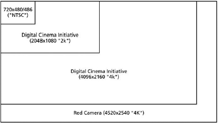
Figure 4.7 Resolutions compared.
Pixel Aspect and Aspect Ratio
In standard-definition PAL and NTSC video, the pixels are not square. They are rectangular—a little taller than they are wide, resulting in a pixel aspect ratio of 0.9 to 1.
Most high-definition formats use square pixels. However, there are a few anamorphic HD formats that use nonsquare pixels to create their widescreen aspect ratio (for example, Panasonic's DVCPRO HD).
Computer monitors use square pixels.
These distinctions are especially important when designing graphics for video or displaying graphics or square-pixel video on nonsquare devices such as NTSC television. For more information about designing graphics for video and how to compensate between square and rectangular pixels, check out the previous chapter. For much more information, see Richard Harrington's excellent book Photoshop for Video, 3rd ed. (Focal Press).
If pixel aspect describes the ratio of width to height of an actual pixel, aspect ratio describes the ratio of width to height of the entire image. This ratio is often described with numbers such as 4 × 3 and 16 × 9, or in decimals such as 1.33:1 or 1.78:1. HD formats are 16 × 9; SD formats are most often 4 × 3.
Progressive vs. Interlaced
There has been quite a bit of discussion over the past few years about progressive scan and interlacing. This is because extended-def formats such as 480p (think progressive-scan DVD players) and high-def formats such as 720p and 1080i have come to the foreground.
If you've ever loaded film into a projector, you know that the motion picture is actually made up of still images projected at speed to produce motion. This works great for projecting film, but when TV was invented, limitations of technology and the need to conserve transmission bandwidth led in the 1930s to the development of interlacing.
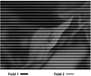
We already know that an NTSC image is made up of 525 lines, of which we see about 486 or 480 in the active image area. In a CRT (cathode-ray tube), these lines are drawn on-screen using an electron beam inside the monitor. In interlaced television, these lines are not drawn onto the screen all at once, but alternately, as two separate images called fields. Put these two pictures together, and you have one frame of video. In NTSC interlaced video, each field happens in about 1/60 of a second. Adding two fields happens in about 1/30 of a second, or one frame of video (30fps). In NTSC, the even (or lower) fields are drawn first, then the odd (or upper) fields.
Ah, More Math! 29.97 and 59.94
Originally, the field rate of NTSC was 1/60 of a second. This number was chosen to match AC power-line frequencies of 60Hz in North America (1/50, or 50Hz, in PAL). Unfortunately, the engineers who designed the specification did so for a black-and-white video signal, and they did not plan ahead for color. So when color television arrived, they had to make a change in the signal. For technical reasons, this turned out to be a 0.1 percent slowdown in the frame rate. This worked out to 29.97fps, leading to a field rate of 59.94fps. (The actual calculation for frames per second is 30×1000/1001, which equals 29.97002997003. For fields, the calculation is 60×1000/1001, which equals 59.940059944006.)
Interlaced video has been the standard for over 50 years, but with the growth of display devices such as LCD, plasma, and DLP over the past ten years, progressive-scan video has come to the forefront. Early in their development, these devices had a very difficult time displaying interlaced video and making it look good. Because there is no electron beam drawing the image on-screen, but rather pixels that are on or off, these devices often show a problem of the interlace system: interlacing artifacts (though CRT devices can also show these problems). These artifacts include interline twitter (a flickering when vertical details in the image appear to shake or move, like fine lines on a shirt) and interlace combing (a “feathering” of the image); they are annoying and ugly. To get around problems with interlaced video, modern displays de-interlace, or remove a field to display the video as progressive.
In progressive video, instead of fields being drawn separately, the image is drawn all at once. Most of us are already familiar with progressive-video devices such as our computer monitors. Progressive scan is much more akin to a roll of film, with each frame being displayed as one whole piece rather than as two separate ones.
Although interlaced video has been given a bad rap recently, there are several benefits to this technology. For one thing, it saves on bandwidth. For another, interlaced images tend to be sharper.
Progressive-scan video is more bandwidth intensive at an equal scan rate. Nonetheless, many viewers feel that progressive-scan images are generally more pleasing and in general have a more filmic quality about them.
Another phrase or concept that has developed with the advent of HD video is PsF, or progressive segmented frames. PsF is a recording scheme in which progressive images are recorded as two separate fields. Hold on a second … . You are asking yourself: “What, then, is the difference between PsF and interlaced?” As previously mentioned, a good way of thinking about interlaced video is that it is really two separate images being displayed alternately. In PsF, there are two fields that are really the SAME image being displayed in alternate fashion. A good use of segmented frames would be HDCAM material shot progressive.
Frame Rate
While the discussion of progressive and interlace formats has been going strong, perhaps no other area has spawned as much discussion and confusion as frame rate. Is it 24 or 23.98? Is 59.94 frame rate or field rate? We admit that this is confusing, and so some further explanation is in order.
If you look at a piece of 8mm film (or even 16mm or 35mm), you will notice that the film is really a series of images When run at speed, these images convey motion. How fast the film moves is known as the frame rate.
Perhaps you've seen an early movie from around the turn of the 20th century and noticed choppy motion—for example, people making erratic movements. This is caused by the film's slower frame rate. If you look closely, you will see what appears to be a lot of flicker in the image. Believe it or not, there actually has been quite a bit of study regarding the physiological effects of frame rate. When film is projected or displayed at a slow enough speed, the viewer can actually detect individual frames and notice flicker. When the film is projected or displayed fast enough, however, the viewer sees the motion as constant (persistence of vision) and without flicker (flicker fusion threshold). Although each person has a different persistence of vision and flicker fusion threshold, these phenomena do exist, and understanding different frame rates is important.
Film is displayed and projected at 24fps (frames per second).
NTSC television is displayed at 29.97fps (originally 30fps—see the earlier discussion for why the frame rate changed).
PAL television is displayed at 25fps.
Okay, so that was pretty easy to understand—but like most things in life, it's not that simple.
With HD formats, the concept of frame rate has become confusing. These formats are often noted by descriptions such as 720p60 or 1080i50. The first part of these equations describes the resolution of the image; the second tells us whether the image is progressive or interlaced; the last part is the image frame rate or field rate. It should be noted that all of the frame rates that we are about to discuss actually describe acquisition and mastering. For all intents and purposes, everything in the NTSC countries is broadcast at 29.97; in PAL countries, this is 25fps.
24—We know that film has a native frame rate of 24. In recent years, there has been a large emphasis placed on 24 frames per second acquisition and recording. This acquisition always takes place as progressive, hence 24p. Whereas some digital cameras and edit systems these days are capable of recording at true 24fps, most record at 23.98fps. This is to maintain compatibility with NTSC broadcasting (trust us, the math works). In the past few years, there has been an explosion of 24p, especially as it relates to DV 24p. This raises some issues (see the sidebar, Understanding Pulldown and 24p).
25—The standard PAL frame rate.
29.97—The standard NTSC frame rate. As previously described, the original frame rate of NTSC was an even 30fps, but due to the introduction of color, this frame rate had to be slowed by 0.1 percent (30 × 1000/1001) to 29.97fps.
30—Originally the frame rate of NTSC video, 30fps is often used for progressive standard-definition video, a.k.a. 30p. And 30p is really 29.97; however, it is progressive rather than interlaced. This is often done to give a “film look.”
Understanding Pulldown and 24p
Everyone likes film! The true 24 frames per second is pleasing to the eye, and in many ways is idolized as the ideal frame rate. The problem has always been trying to get 24 progressive frames per second to work with 29.97 interlaced frames per second for broadcast. The math can be complicated, but not if you understand pulldown.
To get 24 progressive frames into 29.97 interlaced frames, pulldown is applied. This refers to the resequencing of frames from one frame rate to another. This added pulldown was originally developed to aid in the telecine process of transferring film to video. Known as 3:2 or 2:3 pulldown (or 2:3:2:3 to be more technically accurate), all refer to the same process, albeit in slightly different patterns. Let's take, for example, four frames of film. In the 2:3 pattern, the first frame (or A frame) is pulled down to one full frame of video (two fields). The B frame is pulled down to the second frame of video (two fields) and to the first field of the third frame of video. The C frame is pulled down to the second field of video frame 3, and to the first field of video frame 4. The D frame is pulled down to the second field of video frame 4, and as both fields in video frame 5. So, by using this pattern, we actually get five frames of interlaced video for every four frames of progressive video.
This all results in the pattern AA BB BC CD DD for a 2:3 pattern, and AA AB BC CC DD for a 3:2 pattern.
Generally speaking, when people say they are using 3:2 pulldown, they are referring to the 2:3 pattern.
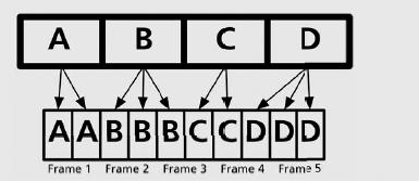
Figure 4.9 3:2 pulldown cadence.
Some cameras, such as the very popular Panasonic DVX100, have a unique take on 24p. In that camera, for example, there are two recording modes. First, 24p Normal, which adds 2:3 pulldown in-camera to give the look of 24fps, but can be captured and outputted as 29.97fps. Then there is 24p Advanced, which has a 2:3:3:2 pattern. When capturing via FireWire, Final Cut Pro can remove this pulldown, getting the video back to true 24p.
Cinema Tools, which is included with Final Cut Studio 2, is also a useful tool for adding or removing pulldown, depending on your workflow.
50—Here is where the confusion between frame rate and field rate starts. PAL has a frame rate of 25fps, yet it has a field rate (how often each field is drawn on-screen) of 1/50 second, or 50Hz (50 fields per second = 25fps interlaced). When discussing high-def formats, 50 can refer to 50 frames per second or to 50 fields per second. Here is how to tell the difference: When a format is interlaced, 50 generally refers to fields per second (e.g., 1080i50). Because there are 50 fields per second, this still equals 25 frames per second. When progressive, 50 generally refers to 50 frames per second. In the case of 720p high def, the resolution is roughly half that of 1080 high def, so frame rate can be increased and fill about the same bandwidth—for example, to 720p50 (note that 720p50 is not actually supported in FCP).
59.94—The same as 60. Due to the need to keep compatibility with 29.97, field and frame rates that are noted as 60 are really 59.94. For example, 720p60 would more accurately be described as 720p59.94; however, it's easier just to use a whole number.
60—NTSC has a frame rate of 30fps, and has a field rate (how often each field is drawn on-screen) of 1/60 second, or 60Hz (60 fields per second = 30 frames per second interlaced). When discussing high-def formats, 60 can refer to 60 frames per second or to 60 fields per second. Here is how to tell the difference: When a format is interlaced, 60 generally refers to fields per second—that is, 1080i60. Because there are 60 fields per second, this still equals 30 frames per second. When progressive, 60 generally refers to 60 frames per second. In the case of 720p high def, the resolution is roughly half that of 1080 high def, so frame rate can be increased and fill about the same bandwidth—for example, to 720p60. An exception to this general rule is 1080p60, which is the best of the best when it comes to HD. It is full resolution and has a superhigh frame rate of 60fps. Please note that when discussing any 60i or 60p format, the actual frame rate/field rate is 59.94 in order to be compatible with NTSC's frame rate of 29.97.
Timecode
Put simply, timecode is a way of identifying frames on a tape. Standardized by SMPTE in the late 1960s, timecode comes in two flavors—dropframe and non-dropframe, which we will look at momentarily. First, let's look at a typical timecode—01:24:41:12 is an example of a typical timecode readout. Read from left to right, it means 1 hour, 24 minutes, 41 seconds, and 12 frames. The pattern is HH:MM:SS:FF, where the FF number will always be the highest frame for a given frame rate. In NTSC, for example, this would be 29 frames; in PAL, 24 frames. The counting is always zero based, meaning that the 30th frame in NTSC or the 25th frame in PAL is the next whole second.
Timecode is occasionally seen with a semicolon prior to the frames (for example, 01:23:14;16). This distinction is to identify dropframe (with the semicolon) and nondropframe (with a colon). Let's look at the difference.
NTSC video operates at 29.97 frames per second, but we count it at 30 frames per second. This discrepancy means that over the course of an hour, timecode would actually be 3.6 seconds longer then the actual time! To fix this, engineers came up with dropframe. By “dropping” the first two timecode numbers every minute, except for each tenth minute (10, 20, 30, etc.), timecode will match real time. One thing that dropframe does not do is actually drop real video frames. It is simply a method of counting.
One last area to understand about timecode is how it is actually recorded on tape. There are two methods. Why two, you might ask? In the early days of video, there was no timecode, so the following methods were created as an afterthought and had to be added to the signal.
LTC—Longitudinal timecode (LTC is pronounced “LIT-see”) is added to the video as an audio signal on a dedicated audio track. LTC can be read while the tape is playing or fast-forwarding; when playing very slowly or while paused, LTC cannot be read.
VITC—Vertical interval timecode (VITC is pronounced “VIT-see”) is embedded as part of the video signal itself at the top of the image (outside the normal 480 or 486 lines). Because it is part of the video signal, VITC can be read when playing very slowly or while paused, but often cannot be read while fast-forwarding or rewinding.
When logging and capturing footage, Final Cut Pro uses either LTC or VITC to read timecode from the video device and to populate timecode metadata for your clips. FCP can read both LTC and VITC, and you can actually choose which one to read, or if both are read, in the device-control tab of Audio/Video Settings. Not all video formats have timecode, though. Formats such as VHS do not have timecode, and therefore Final Cut Pro cannot control the device (more on device control below). You will have to capture from those devices using the noncontrollable-device option.
It is also important to note that film has a system of identifying frames called Keycode, and a related system called ink numbers.
Audio Sample Rate and Bit Depth
We've talked a lot about video, but after all, audio is half of the equation, so let's discuss two areas of the audio signal: sample rate and bit depth.
You have probably seen common sample rates for digital audio in manuals, on the Internet, and elsewhere. Numbers such as 44.1kHz or 48kHz refer to audio sample rate. As a general rule of thumb, the larger the number, the better sounding (especially in the higher end) and larger the file will be. Also, like many of the things we've discussed so far, there is a little math involved!
Human hearing ranges from about 20Hz to 20kHz, although in reality these numbers are less for most people. Our range of hearing is important to understanding sample rate. The highest frequency that can be recorded or reproduced by any device is half that of the sampling frequency (the Nyquist-Shannon sampling theorem). For example, if a CD has a sample rate of 44.1kHz, that means the maximum frequency it can produce is 22.05kHz. Most digital video samples audio at 48kHz, for a maximum reproducible frequency of 24kHz! Another common sample rate is 32kHz, with a maximum frequency of 16kHz. For practical purposes, this means that two of these sample rates—44.1 and 48—can reproduce frequencies beyond that of human hearing!
For video purposes, all of these sample rates (32, 44.1, and 48kHz) exceed the maximum reproducible frequency of an NTSC broadcast.
With the appropriate equipment, Final Cut Pro can work with sample rates ranging from 32 to 96kHz.
Audio bit depth is similar to that of video bit depth. Just like a higher video bit depth, where gradients become smoother and there is a larger range of colors that can be used, high bit depth in audio leads to a larger dynamic range and smoother blending between frequencies. Probably the most common bit depth is 16 bit, but some formats are capable of recording 20 bit, or even 24 bit. Again, as a general rule of thumb, the larger the number, the better. FCP can work with bit depths of 8, 16, and 24 bits.
Video and Audio Signal Paths and Deck Control
If you have ever looked a bird's nest of cables and said to yourself, “Wow! This is a great opportunity to rewire the studio,” perhaps you should skip to the next section. But if SDI, HDMI, TRS, and the like sound like acronyms you see on the back of a luxury car while sitting in traffic, please read on.
In this section, we'll take a brief look at common types of connections and their uses.
Video
Analog
Composite—Composite video these days is the lowest common denominator when it comes to video signals—pretty much anything has a composite connection on it. Composite video was the standard type of connection for early video devices such as 1 inch and ¾ inch and even Betacam. This video is called composite because the brightness (Y′, or luma) and the color channels (U and V, or chrominance) are carried as a “composite” down a single pair on a single cable. Composite is the de facto connection on consumer equipment such as VHS players—that is, the yellow jack. In the professional environment, composite connections are often used for low-quality dubbing and low-end monitoring. Composite video connections carry only analog standard-definition video.
S-Video—S-Video (or separate video or Y/C) is the next step up from composite video. Commonly using a four-pin connector, this connection carries video down two separate pairs—one that carries (Y′), or luma, and another that that carries (C), or the chrominance portion of the signal (U,V in the Y′UV model). Because they are carried down separate pairs, the signals benefit from reduced interference between their color and brightness portions. In the professional environment, S-Video connections are often used for dubbing and low-end monitoring. S-Video connections carry only analog standard-definition video.
Component—Component video is the king of analog video. This type of connection carries luma (brightness) on one cable, and than splits chrominance onto two separate cables. Component video allows for much higher quality than composite video or Y/C because it splits the signal into three separate cables, thus eliminating much of the cross talk, or interference, that is inherent to composite and S-Video signals. The first cable, green (Y′), carries the luma portion of the video; red (PR) and blue (PB) carry the color portion of the image. In the professional environment, component video is often used for analog input and output from edit systems and decks, as well as for monitoring.
Digital
FireWire—Pioneered by Apple in the mid-1990s and subsequently adopted by the Institute of Electrical and Electronics Engineers as the IEEE 1394 standard, FireWire has become a standard connection between miniDv, DvCAM, and DVCPRO decks. It has also been adopted as an option on some DVCPRO50 and DVCPRO HD decks from Panasonic, and on some Sony professional decks such as the J3. FireWire is also referred to as i.Link, which is Sony's name for the technology.

Figure 4.10 Left to right: FireWire 400, FireWire 800, DVI, and HDMI connections.
Connections and Cables
When discussing audio and video signal paths, it gets a little confusing—are we talking about the connection, the part on the end of the cable, or are we talking about the actual cable?
Most professional video cables, such as component and SDI, use 75-ohm coaxial cable. This cable is standardized using a simple protocol: RG-X, with X being the category of cable. Professional video cables most often use RG-6 and RG-59 type 75-ohm coax.
For the actual connectors, there are numerous types. Some of the most common are:
RCA—This is a standard connection type for consumer equipment. RCA connectors are used for audio and for video. These connections are typically color coded: yellow for composite video, red for the right channel in stereo audio, white for the left channel in stereo audio. In analog component bundles, red is for PR, blue is for for PB, and green is for Y′. Orange is for digital coaxial audio S/PDIF.
BNC—Bayonet Neill-Concelman; or, if you really want to impress your friends, British Naval Connector. The Bayonet Neill-Concelman connector, so named for its inventors, is the standard type for professional video connections. BNC connections are also sometimes used with AES/EBU digital audio signal paths. A defining characteristic of the BNC connector is a twisting lock that prevents accidental unplugging.
XLR—most commonly found in professional audio devices as well as microphones, the three-pin XLR connection carries balanced audio. Two of the pins carry the signal—one of these is the normal-polarity, or “hot,” signal; the other is the inverted-polarity, or “cold,” signal. Combined with the third pin, or “ground,” a balanced connection is created.

FireWire comes in two varieties: 400Mbps and 800Mbps. FireWire 400 is the connection most often found on decks and computers, and has two different connectors—a six-pin (generally found on computers) and a four-pin connector (generally found on decks). FireWire 800 and its nine-pin connectors are not as widespread for video purposes as FireWire 400 is, but FireWire 800 is starting to be found on HD video interfaces such as AJA's Io HD. FireWire carries digital audio, video signals, and device control.
DVI—Originally designed for the computing industry, Digital Visual Interface became a standard connection in home theaters for connecting displays to sources such as cable boxes (using the DVI-D variant). In professional video, DVI is sometimes used for connecting display devices such as LCD and plasma monitors, as well as projectors. DVI is being superseded by HDMI.
HDMI—High-Definition Multimedia Interface. HDMI has become a standard digital connection on display devices. HDMI supports uncompressed high-definition video and digital audio, and even device-control signals. Compared to FireWire, HDMI allows for larger bit depths and full-color resolution. Although still used mainly as a connection type for display devices, it is also being adopted in the industry as a connection type to nonlinear editors from decks and cameras.
SDI—Serial Digital Interface. SDI is the de facto standard connection type for higher-end digital decks such as Digital Betacam and DVCPRO50, and for high-definition formats such as HDCAM and DVCPRO HD. SDI carries uncompressed 4:2:2 digital component video. This connection type comes in two flavors. The first, SD-SDI, which is covered under the SMPTE 259M standard, transmits 270Mbps of component digital video and can also carry audio, all along one cable. The second type is HD-SDI. As the name suggests, HD-SDI can carry higher-bandwidth (1.485Gbps) component video with audio; it is covered under the SMPTE 292M standard. It should be noted that although there are specific cables geared to transmission of HD-SDI signals, in most cases—especially for shorter runs—the same actual coaxial cable can be used for SD-SDI and HD-SDI. Transmission differences take place on the decks and capture devices.
Dual-Link SDI—As its name suggests, dual-link SDI uses two HD-SDI connections to transmit ultrahigh-resolution HD video. This standard, also known as SMPTE 372M, supports 10-bit 1080p formats, and is capable of supporting true 4:4:4 R′G′B′ video. Sony's HDCAM SR, for example, can record and transmit 4:4:4 R′G′B′ video over a dual-link connection.
3-Gig SDI—A relatively new standard (SMPTE 424M) can technically do the same thing as dual-Link SDI; however, it simplifies the connection process by eliminating the second cable. Thus, 3-gig SDI can transfer the same 2.97Gbps that dual-link SDI can, but does so along one cable. There are not that many devices currently that use this connection, but it is only a matter of time before 3-gig SDI becomes widespread.
Audio
Unbalanced—An unbalanced audio connection is standard for consumer devices. Often an unbalanced audio connection uses RCA connections. In an unbalanced connection, the signal travels down the cable and there is only one connector. These connections are prone to hum and other interference. Unbalanced audio connections usually carry consumer “low- level” line-level audio (−10dBm). This number is calculated by comparing it to a reference signal. The connections you use to hook up your headphones and stereo speakers are of this type.
Balanced—Balanced audio is a standard for professional audio devices. The most common connection for balanced audio devices is the XLR, although another type, called TRS (tip-ring sleeve), is also sometimes used for balanced connections. Balanced audio is made up of three parts: the normal-polarity, or “hot,” part of the signal; the inverted-polarity, or “cold,” part of the signal; and the ground. In an XLR connection, this is done with three pins. In a TRS connection, it is done using the tip, which is “hot”; the ring, which is “cold”; and the sleeve, which is the ground. This construction resists outside interference, or noise. Balanced audio connections usually carry professional “high-level” line-level audio (+4dBm). Like low-level audio, this number is calculated by comparing it to a reference signal.
AES/EBU—A digital audio connection developed by the Audio Engineering Society and the European Broadcasting Union. In addition to describing a connection, this also represents a standard (officially AES3). AES/EBU audio can stand for a method of combining two channels of 48kHz audio onto one signal, but more broadly it simply describes a protocol of transferring digital audio. AES/EBU is found most often on professional-level equipment. AES/EBU connections come in more than one flavor, and are most commonly found using an XLR connection, although they can also use a BNC connection.
S/PDIF—Sony/Philips Digital Interface Format. This digital audio connection carries AES/EBU audio on either RCA cables or TOSLINK optical cables. Although found on some professional gear, S/PDIF is more commonly used in the world of home theater.
SDI—As noted previously, SDI can carry video along with audio. Known as embedded audio (AES/EBU audio is embedded in the signal), SDI can carry up to eight channels of uncompressed audio.
HDMI—Like SDI, HDMI can also carry an audio signal. The new HDMI 1.3 standard has expanded audio support.
Deck Control
As we will see in Chapter 5, a key concept for nonlinear editing is deck control, which allows the computer to control the deck as a peripheral. This means that you can play, stop, fast-forward, and so forth, using the computer interface and without touching the deck. The following is a list of common deck-control protocols.
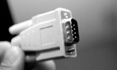
RS-422—A standard communication protocol for professional video decks. RS-422 uses a nine-pin connector to attach a deck to a video-capture device. Standard deck-control operations (fast-forward, rewind, shuttle, jog, etc.) can be sent via this protocol. RS-422 is frame accurate and is supported by Final Cut Pro.
RS-232—A relative of RS-422, this is a standard protocol. Often used on lower-end or older decks, RS-232 is supported by Final Cut Pro.
FireWire—Besides being able to transfer video and audio, FireWire can also transfer device-control instructions. However, FireWire is not a dependable frame-accurate device-control protocol.
HDMI—Much like FireWire, High-Definition Multimedia Interface can carry video, audio, and device control. New devices—such as Blackmagic's Intensity Pro, Sony's HDR-HC3, and Panasonic's HDC-SD1—are all capable of HDMI device control, along with high-resolution video and audio.
Common Digital Formats
For your reference, let's take a look at some common digital and analog formats. Of course there are other formats on the market, but this list represents some of the most popular. Prior to starting a production or postproduction project, it is recommended that you discuss with all of those involved which format best suits a given project.
DV-25
What it is: The format that started the revolution! DV-25 has become synonymous with desktop editing. It is the encoding algorithm frequently used for miniDV, DVCAM, and even DVCPRO tape formats. DVCAM, marketed by Sony, runs at a slightly faster speed and uses locked audio (where each frame of audio is locked to a frame of video). DV and DVCAM are both shooting and studio recording formats.
Tech specs: DV-25 records a 4:1:1 (for NTSC; 4:2:0 for PAL) 8-bit signal with 5:1 compression at 25Mbps. DV-25 includes two channels of 48kHz 16-bit audio, or four channels of 32kHz 16-bit audio on small or large cassettes. Recording time depends on which tape speed you are using.
Interfacing with FCP: FireWire is the simplest method of transferring DV-25 video and audio. FireWire can also be used to provide deck control. Some higher-end DV-25 decks, such as the Sony DSR-1800, can also use SDI with RS-422 deck control.
DVCPRO
What it is: A variation of DV-25, DVCPRO is marketed by Panasonic and is often touted as having better dropout resistance than DV or DVCAM. Although not as common as DV and DVCAM, DVCPRO decks can play both of those formats. DVCPRO is a shooting and a studio recording format.
Tech specs: DVCPRO records a 4:1:1 8-bit signal with 5:1 compression at 25Mbps for both NTSC and PAL, as well as two channels of 48kHz 16-bit audio to small or large cassettes that use 6.35mm tape.
Interfacing with FCP: FireWire is the simplest method of transferring DVCPRO video and audio. FireWire can also be used to provide deck control. However, many DVCPRO decks do not have FireWire, so SDI is the best method of transfer. Device control is through RS-422.
DVCPRO50
What it is: DVCPRO50 is a professional video format from Panasonic. Although only an 8-bit format, it is sometimes compared to the 10-bit Digital Betacam format in terms of overall visual quality. DVCPRO is a very popular format for television, corporate, and indie filmmaking because it delivers great results—and usually for a lower price than Digital Betacam. DVCPRO50 is both a shooting and a studio recording format.
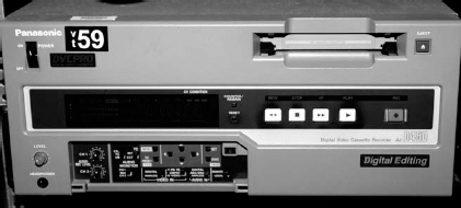
Figure 4.13 Panasonic DVCPRO deck.
Tech specs: DVCPRO50 records a 4:2:2 8-bit signal at 50Mbps (hence the name), with a mild 3.3:1 compression and up to four channels of 48kHz 16-bit audio onto both small and large cassettes that use 6.35mm tape.
Interfacing with FCP: Through a digital capture device, FCP can capture SD video and embedded audio through SD-SDI. With FireWire-equipped DVCPRO50 decks such as the AJ-SD930B from Panasonic, FCP can capture DVCPRO50 through FireWire, and can also remove advanced 2:3:3:2 pulldown via Firewire. If desired, many digital capture devices also support AES/EBU digital audio capture. Device control is through RS-422.
Digital Betacam
What it is: Digital Betacam is the de facto standard for SD recording. Along with D-5 (described next), it is the only other 10-bit SD format. Digital Betacam is a shooting and a studio recording format and is less expensive than D-5.

Figure 4.14 Sony Digital Betacam deck.
Tech specs: Digital Betacam records a 4:2:2 10-bit signal with a very light 2.5:1 compression at 90Mbps, with up to four channels of 48kHz 20-bit audio onto both small and large ½-inch Betacam-based tapes.
Interfacing with FCP: Through a digital capture device, FCP can capture SD video and embedded audio through SD-SDI. If desired, many digital capture devices also support AES/EBU digital audio capture. Device control is through RS-422.
D-5 SD
What it is: D-5 SD's claim to fame is that it is the only 10-bit truly uncompressed studio recording format on the market. D-5 is not an acquisition format.
Tech specs: D-5 SD records a 4:2:2 10-bit uncompressed (170Mbps) signal with up to four channels of 48kHz 16-bit audio onto a medium or large D-5 ½-inch tape cassette.
Interfacing with FCP: Through a digital capture device, FCP can capture uncom-pressed SD video and embedded audio through SD-SDI. If desired, many digital capture devices also support AES/EBU digital audio capture from a D-5 SD deck. Device control is through RS-422.
Betacam SX
What it is: Although not very common in many postproduction workflows, Betacam SX is still relatively common in the news. Betacam SX is a shooting and a studio recording format. Betacam SX was replaced by Sony's MPEG IMX, and more recently has been transplanted into other formats such as XDCAM and P2.
Tech specs: BetaSX records a 4:2:2 8-bit signal with MPEG-2 compression at 19Mbps and four channels of 48kHz 16-bit audio onto small and large ½-inch Betacam-based cassettes.
Interfacing with FCP: Through a digital capture device, FCP can capture SD video and embedded audio through SD-SDI. If desired, many digital capture devices also support AES/EBU digital audio capture from a BetaSX deck. Device control is through RS-422.
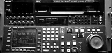
MPEG IMX
What it is: MPEG IMX, as the name suggests, is an MPEG-2 recording format. The interesting thing about MPEG IMX is Sony's push to make the decks more of a piece of network hardware than a simple video deck. Using a special card in the IMX deck with the proper software, the deck itself becomes visible on the network as an e-VTR. IMX media can be transferred over a network rather than using traditional video infrastructure. IMX is also at the core of systems such as Sony's XDCAM.
Tech specs: MPEG IMX records a 4:2:2 8-bit signal of I-frame-only MPEG-2 (discussed in the next chapter) at 30, 40, or 50Mbps with either four channels of 48kHz 24-bit or eight channels of 48kHz 16-bit audio.
Interfacing with FCP: Through a digital capture device, FCP can capture SD video and embedded audio through SD-SDI. Media can be imported (from an e-VTR or an existing file on disk) into FCP using Telestream's MXF component plug-in that “unwraps” the IMX file into a .mov file (more on this in the next chapter). If desired, many digital capture devices also support AES/EBU digital audio capture from an MPEG IMX deck. Device control is through RS-422.
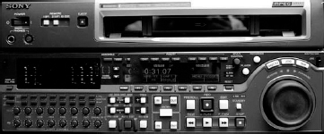
Figure 4.15 Sony MPEG IMX deck.
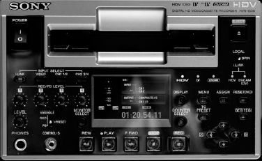
HDV
What it is: HDV has done for high definition what DV did for standard definition. HDV is considered by some to be a consumer format, but its use is widespread in professional circles as well. In recent years, HDV has exploded—it is now available in 1080 and 720 variants at various frame rates, including 24p (ProHD from JVC).
Tech specs: HDV records a 4:2:0 8-bit signal using MPEG-2 compression at 25Mbps for 1080, and at 19.7Mbps for 720. The 1080 images are spatially subsampled, This means that a 1920 × 1080 image is recorded 1440 × 1080, but displayed at 1920 × 1080 in FCP and on a monitor. “Squeezing” a video image to record a widescreen frame onto a format that is not widescreen is known as anamorphic. The 720 images are not subsampled. HDV records two channels of 48kHz 16-bit MPEG-1 Layer II compressed audio onto miniDV tape.
Interfacing with FCP: The easiest method for interfacing HDV with FCP is with FireWire. Using FireWire is limiting in some situations, such as dubbing to other HD formats and with some facilities infrastructure. Devices such as the Miranda HD-Bridge DEC+ can convert HDV over FireWire to SD/HD SDI with embedded audio, and can convert FireWire device control to RS-422 to be used with a digital capture device.
DVCPRO HD
What it is: Also known as DV100, DVCPRO HD is a professional format that is very popular for high-definition acquisition. DVCPRO HD is both a shooting and a studio recording format, and both cameras and decks can record in 720 or 1080 lines. The Panasonic AJ-HDC27, also known as the VariCam, is a very popular DVCPRO HD camcorder capable of recording various speeds from 4fps all the way to 60fps.
Tech specs: DVCPRO HD records a spatially subsampled (720 and 1080) 4:2:2 8-bit signal at 100Mbps with 6.7:1 compression onto small or large cassettes that use 6.35mm tape with up to eight channels of 48kHz 16-bit audio. Spatially subsampling the material works in the following method: A 1920 × 1080/60 (NTSC) image is subsampled to 1280 × 1080, a 1920 × 1080/50 (PAL) image is subsampled to 1440 × 1080, and both a 1280 × 720/60 and a 1280 × 720/50 image are subsampled to 960 × 720 (note that FCP doesn't currently support 1280 × 720/50 images). Another way to think of subsampling is that the image is recorded as nonsquare pixels. Once digitized, FCP and other apps in the FCP Studio can compensate for this and display the image correctly as square pixels.
Interfacing with FCP: Through a digital capture device, FCP can capture HD video and embedded audio through HD-SDI. With a FireWire-equipped deck such as the Panasonic AJ-HD1400, FCP can capture DVCPRO HD through FireWire. In the case of VariCam footage using FireWire, FCP can remove pulldown to get back to the overcranked or undercranked frame rate. Cinema Tools can also be used. If desired, many digital capture devices also support AES/EBU digital audio capture. In most applications, device control is through RS-422, but can be FireWire.
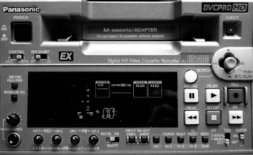
Figure 4.17 Panasonic DVCPRO HD deck.
HDCAM
What it is: HDCAM is generally considered the Betacam SP of high definition. It's everywhere! HDCAM is a shooting and a studio recording format. Although solely a 1080-line shooting format, some studio decks are capable of outputting 720. In some applications, HDCAM is being supplanted by HDCAM SR, but the former is still a very popular format for shooting and studio recording.
Tech specs: HDCAM records a 3:1:1 8-bit signal with 4.4:1 compression at 144Mbps and four channels of 48kHz 20-bit audio onto ½-inch Betacam-derived tape. Like DVCPRO HD, HDCAM subsamples the 1920 × 1080 image to 1440 × 1080. HDCAM can shoot and record at a variety of 1080 frame rates, including 24p.
Interfacing with FCP: Through a digital capture device, FCP can capture HD video and embedded audio through HD-SDI. If desired many digital capture devices also support AES/EBU digital audio capture. Device control is through RS-422.
HDCAM SR
What it is: The latest and the greatest from Sony. HDCAM SR is a new format, but is already being proclaimed the top dog in the HD market. HDCAM SR is capable of both 1080- and 720-line recording (only 720p60), and is both a shooting and a studio recording format.
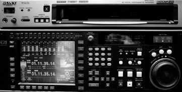
Figure 4.19 Sony HDCAM SR deck.
Tech specs: HDCAM SR records either a 4:2:2 Y′CBCR or a 4:4:4 R′G′B′ 10-bit signal with MPEG-4 compression. When recording in standard quality of 440Mbps in 4:2:2 mode, it uses 2.7:1 compression; in 4:4:4 R′G′B′, it uses 4.2:1. Some HDCAM SR decks, such as the portable SRW-1 from Sony, can record 4:4:4 R′G′B′ video at 880Mbps with a lighter 2:1 compression. This is known as 2x, or HQ, mode. HDCAM SR records up to 12 channels of 48kHz 24-bit audio.
Interfacing with FCP: Through a digital capture device, FCP can capture 4:2:2 Y′CBCR uncompressed HD video and embedded audio through HD-SDI. Because HDCAM SR supports 4:4:4 R′G′B′, video can be captured through dual-link HD-SDI. If desired many digital capture devices also support AES/EBU digital audio capture. Device control is through RS-422.
D-5 HD
What it is: Until recently, D-5 HD has been considered the de facto standard for HD studio recording. Its main competitor is HDCAM SR, but D-5 still remains a viable format simply because it provides amazing picture quality that is less expensive than the HDCAM SR (as of May 2007). D-5 HD is capable of recording all of the 720 and 1080 variants, but is only a studio recording format.
Tech specs: D-5 HD records a 4:2:2 8-bit signal with 4:1 compression, or a 4:2:2 10-bit signal with 5:1 compression at 269-323Mbps, depending on format. D-5 HD records up to four channels of 24-bit audio, or eight channels of 20-bit audio, onto a ½-inch D-5 cassette.
Interfacing with FCP: Through a digital capture device, FCP can capture HD video and embedded audio through HD-SDI. If desired, many digital capture devices also support AES/EBU digital audio capture. Device control is through RS-422.

Figure 4.20 Panasonic D-5 HD deck.
Common Analog Formats
Although there are a multitude of analog formats still to be found in the dark alleys of postproduction, the world in which we now find ourselves is a digital one. So, rather than detail a lot of analog formats, let's take a look at the two most common analog formats that we encounter on a daily basis.
VHS/S-VHS
What it is: VHS is the format we have all come to hate … . I mean love! The winner of the format war with Sony's Betamax, VHS has been largely supplanted by DVD in almost every consumer respect. VHS/S-VHS will most likely remain a format that has to be dealt with from time to time in the postproduction world.
Tech specs: VHS uses ½-inch cassettes with composite recording. VHS can have one or two channels of linear audio (audio that runs on the edge of a tape), or two channels of AFM (audio frequency modulation) stereo audio—better known as hi-fi. This is recorded in the same path as the video. S-VHS improved the overall visual quality of VHS, and in most cases also provided S-Video (Y/C connectors) for improved visual quality when connected to a compatible display device.
Interfacing with FCP: Using an analog capture device, FCP can capture analog composite or Y/C video and unbalanced analog audio. There is no deck control available for VHS/S-VHS, so FCP must use Capture Now in order to capture (more about this in Chapter 7: Ingest).
Betacam SP
What it is: Probably one of the most popular professional formats of all time. This analog format was a standard broadcast format for almost 30 years. Finding a home in production and postproduction, Betacam SP is still in use today. However, BetaSP machinery is no longer made by Sony, due largely to proliferation of DV and other digital formats.
Tech specs: Betacam SP uses ½-inch metal tape and analog component recording. BetaSP is available in small (maximum length: 30 minutes) and large (maximum length: 90 minutes) cassettes.
Interfacing with FCP: Using an analog capture device, FCP can capture analog Y′PBPR component video and balanced analog audio. Deck control is RS-422. Equipment such as the J Series and other higher-end Sony decks can play Betacam SP because they are based on the same transport system.
Other Digital Acquisition and Recording Formats
For years, the postproduction market has been dominated by tape. Recently, the market has seen the next force in acquisition and recording formats: tapeless. Instead of recording to tapes, these new formats record sound and images to optical, disk-drive, or solid-state media. Tapeless formats have several advantages over tape:
- Not being tape-based, these formats do not have the inherent problems that tape does—for example, tape hits, slow rewind and fast-forward times, and tape jams.
- Tapeless formats tend to be more flexible than tape-based formats are. For example, Panasonic's P2 format is capable of recording anything from DV up to DVCPRO HD at multiple frame rates.
- The time benefits of tapeless acquisition are undeniable. Transferring footage without having to digitize allows for streamlined postproduction workflows.
Our main focus is the two most popular tapeless formats: P2 and XDCAM. This is because these two are the most solidified in the marketplace. It is important to note that there are other tapeless formats available.
Formats such as Thomson Grass Valley's Infinity and Ikegami's Editcam systems are just as exciting as P2 and XDCAM, but have not gained widespread commercial appeal. Just like P2 and XDCAM, both Infinity and Editcam use MXF wrappers. However, there is no native support of these formats directly in FCP. Via USB 2.0, Telestream's MXF components can extract the DV, DV-50, or IMX media from these formats for use in FCP.
AVCHD, developed by Sony and Panasonic, employs the MPEG-4 AVC (MPEG-4 Part 10), better known as the H.264 codec, to greatly improve image quality and decrease storage requirements compared to the MPEG-2 system that many HD systems currently use. AVCHD will also allow for the recording of up to 7.1 digital audio. The neat thing about this format is that it can use many different types of media, such as miniDV, hard disk, and solid state. Although some products currently exist, there is as of yet no widespread adoption of AVCHD.
Also on the horizon for late 2007 is XDCAM EX, which is Sony's first solid-state recording system. Employing 34mm express cards dubbed SxS cards, the format will shoot 1080 and 720 at multiple frame rates, including 24, and is seen as a direct competitor to P2.
Although not technically a format, Focus Enhancements’ FireStore allows cameras with FireWire ports to record directly to disk, and to have media directly available for FCP.
Lastly, let's not forget about the digital cinema market. A number of high-end tapeless acquisition products exist, but price and lack of commercial appeal have limited their widespread adoption.
One thing is for sure: tapeless acquisition marks a sign of things to come.
P2
What it is: P2 (Professional Plug-in) is a solid-state recording medium from Panasonic. It allows for recording of DV-25, DVCPRO, DV-50, and DVCPRO HD in multiple frame rates onto the P2 card. P2 is a shooting and a studio recording format, although it is commonly used only to shoot.
Tech specs: P2 records DV-25, DVCPRO, DVCPRO50, and DVCPRO HD with multiple frame rates, with media contained inside an MXF wrapper. Technical specifications are the same as those formats. Cameras, readers, and decks typically have two to five card slots, thus allowing for spanning of footage over multiple cards.
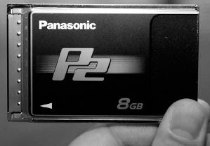
Figure 4.21 Panasonic P2 card.
Interfacing with FCP: The first step to transferring P2 footage is to mount the P2 card(s). This can be done in several ways: (1) Because a P2 card is essentially a PC card, one can use a PC card reader, or even the internal PC card slot found on an Apple PowerBook (note: you must download and install the P2 driver software from Panasonic's web site). (2) Use any of the Panasonic P2 card readers or the P2 store unit. (3) Configure a P2 camera as the card reader. With any of these methods, use the Log and Transfer utility inside FCP to transfer the footage. You can also use a P2 camera as a traditional VTR, and capture the material via FireWire using Log and Capture in FCP (more on this in Chapter 7: Ingest). Lastly, you can also use a P2 deck such as Panasonic's AJ-SPD850 to capture P2 footage via SDI with RS-422 deck control.
XDCAM SD and HD
What it is: XDCAM is a tapeless format that uses Sony's blue-laser technology (similar to that of Blu-ray DVD) to record SD (XDCAM SD) or HD (XDCAM HD) images onto 23.3GB media dubbed Professional Disc (there is also a 50GB dual-layer version). XDCAM has grown quite considerably over the past few years, with exceptional growth in news and sports.
Tech specs: XDCAM uses either DVCAM or IMX recording for XDCAM SD, and therefore the tech specs are the same as for those formats. XDCAM HD uses 4:2:0 MPEG-2 in three modes: 18Mbps (LP), 25Mbps (SP, essentially HDV), and 35Mbps (HQ). Both XDCAM SD and XDCAM HD wrap media in an MXF container. XDCAM HD, like HDCAM and DVCPRO HD, subsamples the image down to 1440 × 1080. XDCAM supports up to four channels of 48kHz 16-bit audio. At NAB 2007, Sony announced the next generation of XDCAM HD, which will shoot 4:2:2 at 50Mbps! This camera will be accompanied by a deck with matching specs. As of May 2007, these devices were not yet commercially available.
Interfacing with FCP: Here is how to interface XDCAM material in FCP: (1) Transfer XDCAM material via FireWire using Sony's XDCAM transfer software (available from Sony's web site). This software will unwrap MXF containers and deliver compatible QuickTime files to FCP. (2) Use Telestream's MXF components to browse, unwrap, and import XDCAM footage from an Ethernet-equipped XDCAM or XDCAM HD deck. Lastly, much like P2, XDCAM footage can be digitized via SDI with RS-422 control.
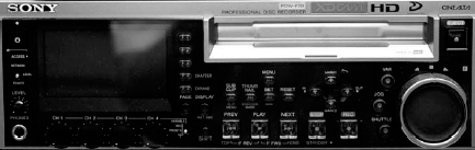
Figure 4.22 Sony XDCAM HD deck.
Capture Cards and Boxes
Now that we have a good working knowledge of the history of video formats, connection types, and stats for common modern video formats, there are a few more pieces of the hardware puzzle: capture cards and hard drives. First, we take a look at capture cards. We save drives until the next chapter.
The purpose of the capture card is to interpret the video signal for the computer.
Whether you realize it or not, all Apple computers have a built-in capture card: your FireWire port! That's right—Apple has been nice enough to provide a high-quality digital interface to decks. Although most often used for mini and DVCAM decks, as previously mentioned, some higher-end decks are now using FireWire as an option.
FireWire is often a nice, convenient option, but it doesn't work in all situations. For one thing, it does not have a high enough transfer rate for some video formats. Secondly, it is strictly a digital-to-digital device, so additional hardware will be needed for any analog decks. Many third-party manufacturers make the cards and devices that support video capture.
Over the past few years, two major players have dominated the Mac market for capture cards and devices: AJA and Blackmagic Design.
Both companies offer a range of products for standard-definition, high-definition, and analog and digital connections. You can check them out on the Internet at www.aja.com and www.decklink.com
The Next Step
For the workflow designer, decisions regarding video standards and formats are important, but they are intimately related to another set of concerns. In the next chapter, we will discuss the technical aspects of video compression and storage.