

Solution for engineering workloads
This chapter provides a preview of the solution and architecture for running engineering workloads in cloud-computing environments. To understand how to get the engineering workloads deployed for running in the cloud, you must understand all the components that are part of the solution architecture. This chapter also provides technical computing use case solutions for engineering workloads.
This chapter includes the following sections:
7.1 Solution overview
Under intense market pressure to produce better product designs quickly and cost-effectively, engineering teams are becoming more diverse than ever before. Workgroups are distributed across multiple locations worldwide, each one situated in a different type of regulatory and IT environment. In addition, each workgroup can be using different standards, tools, and processes.
To run resource-intensive simulations, globalized workforces are moving toward a shared high-performance computing (HPC) model in which centralized HPC systems replace local computing infrastructure. This arrangement can work well, but it raises two challenges. First, decentralized data creates versioning issues, especially when different teams need access to the same simulation results. Second, moving large simulation files is time consuming, so much so that the time delay can negate productivity gains made by sharing HPC resources.
In today’s fast-paced environments, aerospace, defense, and automotive companies that develop or manufacture products need speed, agility, control, and visibility across the design environment and lifecycle to meet time-to-market requirements and maximize profitability. IBM technical computing clouds solution for engineering can help these companies transform their design chain to develop products better, faster, and cheaper.
7.1.1 Traditional engineering deployments
Manufacturers face enormous pressures to make products that are stronger and last longer, while reducing cost, increasing innovation, and shortening development cycles. To address these demands, manufacturers need engineering simulation solutions that allow users to design and verify products in a virtual, risk-free environment. This minimizes the need for physical prototypes and tests.
In a traditional engineering environment, computing resources are often deployed in support of a single workload, project, or organization. As a result, computing silos are formed that must be managed and maintained. Thus, user and application portability is limited, and often allocated resources fail to meet demand. The outcome is uneven and constrained processing across your organization, higher costs, and the potential for delayed results.
Compute cluster
When engineers work remotely, they access engineering applications and centralized product development centers from a notebook, desktop, web browser, or another rich client. These applications run on hosted servers suitable for computer-aided design (CAD), computer-aided manufacturing (CAM), computer-aided engineering (CAE), process management, and other workloads. What makes these servers work well is the ability to allocate compute, memory, and other resources to workloads dynamically, as well as migrate running workloads from one system to another. Separate technical computing clusters, HPC resources and dynamic job schedulers enable shared, highly utilized analysis environments where engineers can run multiple simulation runs, pre-production runs, and other HPC capabilities.
Deskside visualization
It has been typical to provide costly physical systems to be used as engineering workstations to deliver 3D graphics applications that demand hardware acceleration of a high-end graphics card to efficiently render very large models (millions of vertices) such as airplanes and automobiles. As a result, many engineers today have workstations for 3D design, and others to run enterprise applications and collaboration tools such as email and instant messaging. This multiple workstation model is inefficient and costly. In addition, this workstation model approach does not lend itself well for the type of collaboration necessary to enable real-time review of component designs.
Figure 7-1 illustrates a common workflow found in most traditional engineering environments.

Figure 7-1 Traditional engineering workflow based on deskside visualization
7.1.2 Engineering cloud solution
The engineering cloud solution provides a high performance visual computing environment, enabling remote and scalable graphics without the need for high-end workstations. This open standards-based solution provides a cloud infrastructure environment for organizations that have large 3D intensive graphics requirements and want to reduce costs and improve collaboration between their own designers and remote designers, testers, and component manufacturers. This solution allows engineering designers to use a standard desktop environment to gain access to 3D applications within the 3D Cloud infrastructure without the need for extra graphics cards within their desktop. In addition, the technology enables effective collaboration with local or remote designers, testers, and manufacturers without requiring them to have a powerful desktop system. This collaboration aspect has increased in importance as the workforce has expanded to new locations. With the ability to move 3D applications to a cloud infrastructure, clients can gain economies of scale, enhanced management, improved collaboration, and improved ROI for user workstations.
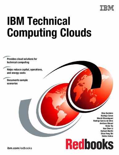
Figure 7-2 shows a generic view of an engineering cloud deployment showing three large cloud infrastructure groups: Desktop, storage, and compute clouds.
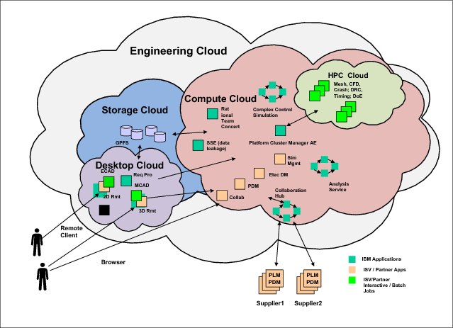
Figure 7-2 Engineering cloud solutions comprehensive deployment view
Desktop cloud
The virtualized 2D or 3D desktop cloud solution allows pre-processing and post-processing to be performed by using commodity hardware such as low-cost notebooks or desktops, instead of expensive high-end workstations. The graphics processing units (GPUs) are present visualization nodes in the remote cluster, alongside the compute nodes. These visualization nodes take care of the rendering for the desktop sessions started by the thin client workstation as shown in Figure 7-3 on page 143. Only the keyboard and mouse events are sent to the 3D session remote server, and only the rendered pixels are exchanged with the client graphics display.

Figure 7-3 Engineering cloud workflow for 3D remote visualization
The solution has a robust but open architecture that allows the client to grow and change their engineering environment as new technologies become available. Because the compute and graphics processing is run in the cloud and commodity hardware is used to display the results, the client can easily and quickly move to newer graphics and cloud technologies as they become available. Figure 7-4 illustrates the advantages of a desktop 3D cloud infrastructure.
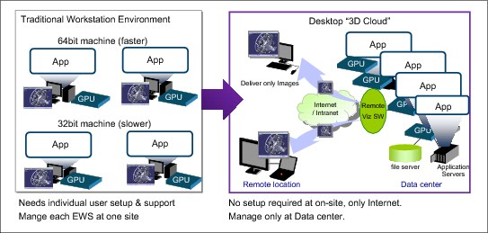
Figure 7-4 Advantages of a 3D desktop cloud infrastructure
Another characteristic of the desktop cloud is higher utilization of GPUs on visualization nodes. By running specialized virtualization software on the visualization nodes, the clients can have multiple desktop sessions on a single GPU.
Compute cloud
On the execution end of the engineering cloud solution, you have HPC clusters with robust workload and resource management for shared, highly utilized engineering environments.
A comprehensive set of management tools is needed to ensure departmental, enterprise, or community resources are optimally deployed, and easy to access and manage. The following are among the services provided:
•Self-service job submission and management.
•Easy to use web-based interface for remote access to shared resources and simplified application integration.
•Dynamic provisioning, job migration, and checkpoint-restart for automatic adaptation to changing workload requirements.
•A centralized environment where remote users run host-based HPC applications.
•Intelligent policy-based scheduling to ensure that application servers and 3D graphics are fully utilized
•Application templates to enable reuse of engineering assets.
Storage cloud
Allocating the correct amount of data storage to the correct users at the correct time is an ongoing challenge for engineering companies of all sizes. The storage cloud can enable you to cost effectively handle electronic documents such as contracts, email and attachments, presentations, CAD and CAM designs, source code and web content, bank check images and videos, historical documents, medical images, and photographs. This multilayer, managed storage virtualization solution incorporates hardware, software, and service components to facilitate simplified data access. Its seamless scalability, faster deployment, and flexible management options can help reduce complexity and costs while enabling your company’s continual growth and innovation.
The storage cloud ties together the engineering cloud infrastructure. Centralized, shared storage allows engineers to access information globally. This is much different from typical environments, in which engineers manage files locally and move them back and forth to HPC resources located elsewhere. For certain types of software simulations, uploading files can take one or two hours, and file downloads can take significantly longer. This can compromise productivity and impede the use of HPC.
7.1.3 Key benefits
The IBM solutions for engineering clouds enable web portal access to centralized engineering desktops and workload optimized private or private hosted HPC clouds. The engineering cloud focuses on mechanical, electronics, and software development domains, and the seamless integration between these domains, including original equipment manufacturer (OEM) and supplier collaboration. With accelerated 2D and 3D remote graphics and modeling, agile systems and workload management, and independent software vendor (ISV) integration, the engineering cloud can help you address multiple customer challenges. These include reducing IT costs, increasing IT flexibility, improving engineer collaboration, and saving engineering time. The following section lists the key benefits of this model.
Distributed and mobile workforce
The following are the benefits of the distributed and mobile workforce model:
•Reduces the time that is needed to complete a design through improved collaboration and skill sharing.
•Allows outsourced and off-shored design staff while storing data and applications centrally.
•Remote collaboration between locations and with external third-party partners.
•Ubiquitous access to the user infrastructure.
•Unlocks designer skills from any location with remote access capabilities.
IT infrastructure management complexity
The following are the benefits of the IT infrastructure management complexity model:
•Transforms siloed environments into shared engineering clouds, private and private-hosted initially, changing to public over time.
•Increases infrastructure flexibility.
•Decreases dependence on costly high-end engineering workstations.
•Supports an infrastructure that is independent of hardware platforms and operating systems.
•Reduces branch office IT support requirements.
•Uses ideal tools, and standardizes processes and methodologies.
•Realizes improved operational efficiency and competitive cost savings.
Security control
The following section describes the benefits of the security control model:
•Patch compliance enhanced because the operating system and applications are centrally managed.
•Manages security risks in data and infrastructure.
•Centralized compliance with regulations.
•Provides greater and more secure access to compute and storage resources.
Cost of workstation management
The following section describes the benefits involving the cost of workstation management:
•Eases deployment/support of desktop systems.
•Makes IT costs predictable.
•Increases operational flexibility.
•Increases resource utilization (processor, GPU).
•Lowers TCO and rapid ROI.
•Improves procurement usage in purchasing of software.
•Achieves significant energy savings.
|
Note: The benefit of the engineering cloud can only be realized if the organization uses CAD/CAE applications that adhere to OpenGL standards for graphics delivery.
|
7.2 Architecture
The engineering cloud solution addresses the increasing demand for faster results in the Technical Computing space.
By placing the high-end graphics applications in an IT cloud infrastructure and providing access to those applications, IT can more effectively maintain a consolidated graphics hardware environment and provide graphics capabilities to new and existing users.
The self-service portal that is used in this solution provides the user with a means to find available engineering applications and engineering assets. Users are able to perform daily work in much the same way as they did in the past. The self-service portal provides administrators with the ability to define and administer engineering users. They can grant those users access to specific engineering applications and determine who can share a design.
The engineering cloud can be an extra service offered by almost any cloud environment already in place. This solution can use existing security services such as LDAP, Directory Services, and IP tunneling. The existing enterprise business administration and management systems can also be used to monitor the systems that are used to provide the engineering cloud services.
|
Note: The engineering cloud solution concepts described here use the Cloud Computing Reference Architecture (CCRA). It is predominately an infrastructure as a service (IaaS), platform as a service (PaaS) and software as a service (SaaS) solution. Note that although the engineering cloud solution is an IaaS component, there are multiple software products within it. The integration and maintenance of these products provides a potential for services.
|
7.2.1 Engineering cloud solution architecture
The architecture that supports the engineering cloud solution is robust yet relatively simple. This architecture supports open standards and can integrate with currently available security and management mechanisms. Although the implementation described here focuses on high-end engineering 3D graphics, it can be used as a platform for other types of 3D and 2D graphics applications.
Figure 7-5 represents the architecture overview diagram of the engineering cloud solution. It shows how the environment can be incorporated into an existing cloud environment and uses existing security, business management, and monitoring. Notice how this architecture relates back to the CCRA.
Figure 7-5 Engineering cloud architecture overview
The items shaded in blue in Figure 7-5 are directly associated with the engineering cloud solution. The items shaded in red are layers and items that most likely already exist in your environment. Any of these items that do not exist in your environment must be added for the engineering cloud solution to be deployed and managed properly.
Cloud service consumer
In the context of an engineering cloud, the consumer is any engineer who needs access to the engineering models. These engineers can be part of a client's organization or part of a third-party organization. They can be local to a single client office or dispersed globally among multiple client offices or third-party partners. Third-party users or collaborators are just another form of cloud consumer user.
Cloud services
The PaaS block in the CCRA is the most prominent piece of the solution. This block represents the specialized hardware and software that are required for this solution, which is provided as a platform to the cloud service consumers.
Depending on how the client sets up their cloud infrastructure, and how the engineering cloud has been inserted, the solution can also be in the IaaS block of cloud services.
Table 7-1 describes generalized definitions to determine whether the engineering cloud is an IaaS or PaaS service.
Table 7-1 Cloud service consumer characteristics
|
Cloud service consumer characteristics
|
Type of service employed
|
|
Has access to and can manipulate the operating system of the Cloud services provided.
|
IaaS
|
|
Only has access to the engineering applications and cannot manipulate the operating system of the cloud services provided.
|
PaaS
|
|
Note: The engineering cloud solution can be set up as both IaaS and PaaS in the same cloud environment, depending on the level of access the cloud service consumer requires and the applications being used.
|
Infrastructure
Because the engineering cloud solution uses specific hardware, there is a strong connection with the infrastructure block as shown in Figure 7-5 on page 147. For more information about the hardware that is required for this solution, see 7.3.6, “Hardware configuration” on page 154.
Common cloud management platform
The engineering cloud solution maps to every block within the operational support services (OSS) and business support services (BSS) of the CCRA. It is important to note here that if you have an existing cloud environment, the engineering cloud solution becomes just another service. Therefore, this solution can take advantage of the processes and utilities already in place for OSS and BSS services in your environment.
7.3 Components
Figure 7-6 takes the architecture overview from 7.2.1, “Engineering cloud solution architecture” on page 146 and adds the components of the solution. As before, the items shaded in blue are directly associated with the engineering cloud solution. The items shaded in red are layers that, most likely, exist in your environment.

Figure 7-6 Engineering cloud PaaS component model
There is room for considerable flexibility in the environment to accommodate specific customer requirements in this architecture. The hardware and software components in this architecture can be implementing using the components described next.
7.3.1 Cloud service consumer
Various internal and external engineers as well as the internal administrators need access to the engineering cloud solution. These engineers and administrators can use various clients to access, monitor, and administer the environment. The access clients can be web browsers, third-party engineering applications (front ends), and others. Other thick and thin clients can be used in this channel as required by line of business applications. Remember that an engineer can be local, remote, or belong to a third-party partner. There is no particular IBM hardware or software that is used here. However, note that this layer runs on commodity hardware instead of high-end graphics hardware.
7.3.2 Security layer
The applications already in use by the customer to control, monitor, and administer their security environment. This includes, but is not limited to, Directory Services, Network Monitoring, employment of encryption, and so on.
This layer can use the breadth of the IBM security portfolio to help ensure trusted identities, manage user access, secure applications and services, and protect data and infrastructure. For more information about security and IBM Platform Computing, see chapter 5 of Security of the IBM Platform Computing Integration Solutions, SG24-8081.
7.3.3 Cloud services provider
There are multiple items and layers represented in the CCRA that can be used as part of the engineering cloud solution. The bulk of these items comprise the cloud service provider area of that architecture. The cloud service provider area contains the cloud services and common cloud management areas of the architecture overview diagram.
Remember that the solution can be deployed as a PaaS cloud service solution or as an IaaS cloud service solution. The deployment model that is used depends on your requirements and engineering applications. The PaaS deployment model was chosen in Figure 7-6 on page 149 because that is the most common deployment of the engineering cloud solution. Five layers are present in the cloud deployment model as described in the following sections.
Self-service portal layer
A self-service portal is used for user and administrative access to the engineering applications. The IBM Platform Application Center (PAC) is an example of such portal. PAC is the suggested portal environment for controlling and accessing engineering applications that are delivered by using the engineering cloud solution. However, it is possible to use other front ends provided by third-party engineering software suites.
Load balancing/workload management layer
The workload management application is required to use the available graphics cloud based resources and spread the work evenly across the available compute resources. The load balancer must be tightly integrated with the 3D desktop virtualization applications so that the GPUs are properly load balanced.
IBM Platform Computing Load Sharing Facility (LSF) is the load balancing engine that can be used to spread engineering workloads across the appropriate compute nodes in the cloud. This application can be found at the Load Balance/Workload Management layer of the architecture overview diagram.
Application layer
Various engineering and non-engineering applications that are managed by the portal and used by the clients. The solution presented here focus on high-end 3D engineering applications, but other 2D engineering and even non-graphics applications can be implemented in this environment. Although there can be IBM applications in this layer, there are no specific IBM products for the engineering cloud in this layer. However, IBM has partnerships with both Siemens and Dassault that provide appropriate and compliant 3D graphics applications.
Virtualization layer
Various components are used for the virtualization layer. There are two different types of virtualization in this solution.
First is the application that encapsulates and compresses the OpenGL graphics for transport to the user clients. Both NICE DCV and OpenText Exceed onDemand (EoD) are third-party applications that are supported to provide this virtualization layer in the engineering cloud solution. For more information about these applications, see 7.3.5, “Third-party products” on page 153.
The other type is the application that manages the compute nodes (virtual machines) in the environment. The example environment uses KVM.
Using KVM allows you to run more than one CAD virtual desktop on a physical server. When used with NICE DCV (Figure 7-7) you can share the GPU among multiple virtual desktops.

Figure 7-7 DCV on Linux and on KVM
NICE DCV supports GPU sharing or virtualization when used on application running on Linux and KVM virtual machines (along with GPU native access when running on Microsoft Windows).
DCV and EoD support different types of deployment. Table 7-2 summarizes the features of each product.
Table 7-2 3D Virtual desktop solution comparison
|
Feature
|
NICE DCV
|
OpenText Exceed onDemand
|
|
Guest operating system support
|
Supports both Linux and Windows (using KVM)
|
Supports OpenGL applications running on Windows, Linux, and AIX application servers
|
|
Multi-user sharing of GPUs
|
Supported
|
Supported
|
|
Direct3D support
|
Not supported
|
Not supported
|
|
Portable devices support
|
Limited support (required for better WAN performance)
|
Supports portable devices (iOS, Thin clients)
|
Infrastructure layer
The server hardware, network hardware, and storage devices needed to connect the engineers to the required virtual hardware and the necessary intellectual property (models) needed to perform their jobs. For more information about the hardware configurations that are required to implement the engineering cloud solution, see 7.3.6, “Hardware configuration” on page 154.
|
Note: IBM iDataPlex dx360 was the base hardware solution used for the example environment. For more information about the IBM iDataPlex family of servers, see:
|
Several IBM storage solutions can be added to this layer such as Scale Out Network Attached Storage and General Parallel File System (GPFS). Note that the network component in the infrastructure layer of this model must be robust enough to handle the clients' bandwidth needs.
Within the IBM portfolio, the Storwize® V7000 Unified and Scale Out Network Attached Storage are two network-attached storage systems that offer storage capabilities with a data-centric view of resources and shared data repositories. These systems can be co-located with the compute resources to optimize engineering workflows and enable increased collaboration through remote access.
Both systems are built on IBM Active Cloud Engine™, which is a powerful policy-driven engine that is tightly coupled with the file system and designed for managing massive amounts of data. Specifically, it manages files in an automated, scalable manner, creating the appearance of a single, fast system regardless of differences in geography, storage media, and other physical factors. IBM Active Cloud Engine enables users to search huge amounts of data, and rapidly store, delete, distribute, and share these data. This is important for engineering software users because it gives users the ability to manage large numbers of files efficiently, locate relevant data quickly and move the data to where it is needed seamlessly.
For more information about file system management, in particular Active File Management (AFM), caching, replication, consistency, sharing, and other topics, see Chapter 6, “The IBM General Parallel File System for technical cloud computing” on page 111.
|
Note: For more information about the solution and its components, see the solution brief “IBM Engineering Solutions for Cloud: Aerospace, and Defense, and Automotive,” DCS03009-USEN-01, at:
|
7.3.4 Systems management
The PAC self-service portal is the primary system management facility for the engineering cloud solution. This portal is the service that is used to define available applications, and the users that can access them. But PAC can also be part of a broader, larger infrastructure layer that is managed by IBM Platform Cluster Manager - Advanced Edition (PCM-AE).
The environment administrator can take advantage of the application templates feature in PAC to define job submission forms for each type of application that is used by the engineering teams. The customizable interface builder enables forms to be easily tailored and selectively shared among users or groups.
Another system management aspect to the engineering cloud solution is the duties/tasks that are performed by the system administrators. The engineering cloud solution requires a specific set of hardware and software resources. Due to these specific resource requirements, the administrators might need to modify existing practices to ensure that the engineering cloud and the engineering sessions created in that environment are provisioned and deployed properly. This is necessary when the engineering cloud solution is deployed as a cluster definition in an existing cloud infrastructure managed by PCM-AE. For more information about PCMAE cluster definitions, see 5.5.1, “Cluster definition” on page 96.
For instance, If the engineering cloud solution is defined as a cluster definition that can be provisioned into an existing PCM-AE cluster infrastructure, that definition must provision a set of engineering specific resources from the available pool of resources. This must be do to ensure that engineering sessions have access to the appropriate hardware and software.
However, if the engineering cloud solution is employed as a stand-alone cloud service, the IBM Platform LSF product runs these provisioning functions. There is only one set of hardware and software resource pools. If the dynamic cluster plug-in is installed, advanced provisioning features are employed to meet software requirements for the engineering jobs. The advantages of dynamic cluster are explained in 2.2.5, “IBM Platform Dynamic Cluster” on page 18. Again, multiple resource pools might be required based on your requirements.
Although the self-service portal adds more management requirements to the existing infrastructure, it eliminates the need to manage individual high-end engineering workstations throughout the enterprise.
7.3.5 Third-party products
This section provides third-party products that are useful when running engineering workloads.
Nice desktop Cloud Visualization (DCV)
This application encapsulates, compresses, and transmits all of the OpenGL graphics information that is used in this solution. For more information, see:
OpenText Exceed onDemand
Exceed onDemand is a managed application access solution that is designed for enterprises. The solution offers pixel drawing, low-cost scalability, and trusted security access over any network connection. For more information, see:
Real VNC Enterprise Visualization
This application allows you to connect to remote sessions (3D Engineering or otherwise). RealVNC is used to connect the engineer with the engineering cloud resources needed. RealVNC establishes connections between computers irrespective of operating system. The RealVNC Viewer is installed on the engineer’s lightweight workstation, and the RealVNC Server is installed on the visualization nodes in the cloud. For more information, see:
3D Engineering CAD/CAE applications
The CAD/CAE applications are not necessary for the solution itself, but are necessary to realize the ROI gained by virtualizing physical high-end engineering workstations. All of these applications are in the application layer of the architectural overview diagram. For more information about ANSYS, a 3D Engineering CAD/CAE application that was used in the example environment, see:
7.3.6 Hardware configuration
The engineering cloud solution uses a specific hardware stack to provide appropriate compute and high-end graphics capabilities in the cloud.
Shared memory systems
Some engineering workloads require large shared memory system to achieve good performance. Therefore, it is important to select the correct server family, processor, and memory so that applications can operate efficiently. For computation, Intel Xeon E5-2600 series (or E5-4600 series), 8-core and 2.6 GHz or faster processors are preferable. Configure sufficient memory using the latest direct inline memory module (DIMM) technology, which offers speeds up to 1600 MHz, so that problems are solved in-core. This eliminates the risk of bottlenecks due to slow I/O.
Clusters and scalability
When one system (node) is not sufficient to solve an engineering problem, multiple nodes are connected with a communication network so that a single problem can be run in parallel. In this situation, the communication delay (latency) and rate of communication among systems (bandwidth) affect performance significantly. IBM server products support InfiniBand switch modules, offering an easy way to manage high performance InfiniBand networking capabilities for IBM server systems.
Storage systems
This section describes the storage systems as part of the hardware solution for storage.
IBM Storwize V7000 Unified
The IBM Storwize V7000 Unified storage system can combine block and file storage into a single system for simplified management and lower cost. File modules are packaged in a 2U rack-mountable enclosures, and provide attachment to 1 Gbps and 10 Gbps NAS environments. For block storage, I/O operations between hosts and Storwize V7000 nodes are performed by using Fibre Channel connectivity. The following are the relevant features:
Number of disk enclosures Up to 10
Size of each enclosure 24 2.5” 1 TB nearline SAS 7.2 K RPM = 24 TB
Total disk capacity of the system 240 TB
Host attachment – File storage 1 Gbps and 10 Gbps Ethernet
Host attachment – Block storage SAN-attached 8 Gbps Fibre Channel (FC)
Entry-level file server with internal storage system
For small or economical environments, an IBM System x3650 M4 can be used as an NFS file server. The x3650 M4 system contains up to 16 internal 1 TB 7.2 K RPM nearline SAS drives with RAID6 configuration. The file system is mounted over the fastest network (Gigabit Ethernet or InfiniBand) provided in the cluster.
Cluster interconnect
An important constraint to consider is network bandwidth and capacity. Although the engineering solution provides great value, it also increases network traffic. This increase in network traffic is because graphics used in the engineering design process are now transported through TCP/IP. When considering this solution, you need to understand how design engineers currently use their graphics applications (length of design effort, frequency of user access, model size, number of simultaneous users, and so on). Conduct a network traffic assessment with your IT staff to ensure that your network infrastructure will be able to handle the projected workloads deployed onto the cloud infrastructure. It might be advantageous if you have a globally dispersed engineering staff to consider the configuration of multiple engineering cloud compute clusters.
Network latency also plays a significant role in the performance of the Engineering 3D Cloud solution. If there is network latency greater than 40 ms between the engineer and the engineering cloud, performance of the graphics applications suffers. The applications still work properly in these instances, but the graphics images will not move smoothly, which might cause user complaints.
Best practices
The specific systems configuration for your engineering solution depends on the workload type and application characteristics and requirements. Here are some configurations tips for servers dedicated to scale-out workloads.
Systems
Configure the systems as follows:
•2-socket-based systems with GPU support
– IBM iDataPlex dx360 M4
– IBM PureFlex™ x240
•2-socket-based systems without GPU support
– IBM System x3550 M4
Processor
The processor has the following characteristics:
•2-socket systems
– Intel Xeon E5-2670 2.6 GHz 8 Core
Memory
Allocating sufficient memory to solve in-core improves performance significantly. Consider this first before you add other resources such as more cores or GPUs. The following are the configuration characteristics (Table 7-3 on page 156):
•Use dual-rank memory modules with 1600 MHz speed
•Use the same size DIMMs
•Populate all memory channels with equal amounts of memory
•A 2-socket system has eight channels
•Populate the memory slots in each channel in this order:
– First slots in all memory channels
– Second slots in all memory channels
Table 7-3 Recommended memory configurations
|
Total memory per node
|
2-socket systems
|
|
64 GB
|
8 x 8 GB DIMMs
|
|
128 GB
|
16 x 8 GB DIMMs
|
|
256 GB
|
16 x 16 GB DIMMs
|
GPU accelerators
The following IBM systems are enabled for GPU usage:
•IBM System dx360 M4 with up to two NVIDIA
•IBM PureFlex System x240 with up to one NVIDIA
Supported GPUs for acceleration:
•NVIDIA M2090
•NVIDIA K10
•NVIDIA K20 and K20X
IBM has published solution guides that are focused on specific engineering ISVs, for example ANSYS. These documents address in more detail each application requirement, providing hardware configuration best practices. See the documents listed in Table 7-4.
Table 7-4 IBM solution and best practice guides for engineering
|
Publication ID
|
Publication name
|
URL
|
|
XSO03160-USEN-00
|
IBM Information Technology Guide For ANSYS Fluent Customers
|
|
|
XSO03161-USEN-00
|
Best Practices for Implementing ANSYS Fluent Software on Cluster Technologies from IBM
|
|
|
TSS03116-USEN-0
|
ANSYS and IBM: optimized structural mechanics simulations
|
|
|
TSS03117-USEN-00
|
ANSYS and IBM: agile, collaborative engineering solution
|
Example configuration
The example environment involved a development cluster configured to provide 3D engineering cloud access to run ANSYS applications. The cluster solution was set up according to the reference architecture described in this book.
Compute node 2-socket system without GPU
The following section describes the hardware and software for the compute node 2-socket system without GPU:
•Hardware
– iDataPlex dx360 M3
– 16 GB RAM
•Software
– RedHat Enterprise 6.2
– DCV 2012.0.4557
– VNC Enterprise Visualization
Compute node 2-socket system with GPU
The following section describes the hardware and software for the compute node 2-socket system with GPU:
•Hardware
– iDataPlex dx360 M3
– 2 NVIDIA Quad 5000 GPU
– 192 GB RAM
•Software
– RedHat Enterprise 6.2
– DCV Version 2012.2-7878
– EoD Version 8
The resources dashboard in Figure 7-8 shows a rack view of the nodes dedicated for the engineering environment. This view in PAC provides the status of each node. The user is logged in as wsadmin, which is an administrator for this cluster instance.

Figure 7-8 The resources dashboard in PAC showing the nodes available in the test cluster
In the hosts view in PAC, as shown in Figure 7-9, you can see the details for each node in the cluster.

Figure 7-9 The example environment shown in the PAC web interface
7.4 Use cases
This section details example use cases that were evaluated in the example environment while accessing the IBM engineering cloud deployment. These use cases use software products developed by ANSYS for computational fluid dynamics and structural mechanics.
The typical user of ANSYS applications performs the following tasks:
•Preprocessing where the engineering model is created using graphics-based applications.
•Solution phase where a simulation of the model is carried out.
•Post processing where the results are evaluated using graphics-based applications.
These tasks are shown in Figure 7-10.

Figure 7-10 ANSYS main use case
The resource allocation to address this use case scenario can be fully distributed, partially distributed, or fully centralized. The use case scenario where the resources are fully distributed such that each workstation is self contained to address all the three steps (Figure 7-10) is not considered in the context of an engineering cloud solution. In this architecture, it is assumed one or more of the three steps are performed on a centralized resource. In practice, the main use case described in Figure 7-10 is to use centralized computing resources in the following two ways:
1. Local workstations and remote clusters
The typical use case is illustrated in Figure 7-1 on page 141. In this case, an ANSYS user prepares data on the workstation using an application such as ANSYS Workbench. The user then submits a simulation job to use the performance and throughput of the cluster. After the simulation is complete, the results are downloaded and viewed on the client workstation. ANSYS simulation software such as ANSYS Fluent and ANSYS Mechanical, which are computationally intensive, run on the cluster.
2. Thin clients and remote clusters:
As shown in Figure 7-3 on page 143, both compute intensive simulation using ANSYS Fluent and ANSYS Mechanical, and graphics intensive visualization run in the cluster environment. The client device can be a thin client with display capabilities instead of a powerful workstation. The only data that is transmitted between the client and the cluster are the keystrokes from the client and the rendered pixels from the cluster.
|
Note: The two use case scenarios are similar, for both ANSYS Fluent and ANSYS Mechanical. However, each of these application areas has slightly different computing, graphics, network, and storage requirements. For example, in the case of ANSYS Mechanical, the memory requirements and data that are generated for post processing during simulation can be significantly larger than for ANSYS Fluent. These differences might have some implications on the selection of cluster resources such as network bandwidth, memory size, and storage subsystem.
|
Desktop Cloud Visualization (DCV) and EoD are used to implement remote rendering requirements of ANSYS application suite. For more information, see 7.3.5, “Third-party products” on page 153. Their use in implementing remote 3D visualization for ANSYS application suite is described in this section. However, the internal architecture and implementation of these components is not covered in this document.
7.4.1 Local workstation and remote cluster
The use case, as shown in Figure 7-11, requires a facility to submit a batch job to the cluster by providing input data sets that are either local to the workstation or in the cluster.
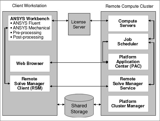
Figure 7-11 Architectural overview of the local workstation and remote cluster use case
The primary interface to the ANSYS Fluent and ANSYS Mechanical is IBM PAC. In PAC, this interface is provided through the application templates.
Each of these templates has the following information embedded in them by the system administrator so that it is transparent to the user (the resources are in the cluster):
•PATH to the application executable file
•License server information
When a new version of ANSYS application is installed, the reference to ANSYS application in PAC must be updated either automatically or by the system administrator.
ANSYS Fluent
When the users click the ANSYS-Fluent template, a web-based form is presented that requests information as shown in Figure 7-12.

Figure 7-12 Using a modified ANSYS Fluent application template to submit a job
|
Note: The input data sets can either be local to the workstation or on the server.
|
After the users provide the information and click Submit, PAC constructs an LSF command that includes all the information that is needed and submits the ANSYS Fluent job to LSF. Optionally, for each job, a temporary working directory is created. If the data sets are on the workstation, they are transferred to a working directory on the cluster. All of the output, if any, that is generated is stored in the same directory. The users can retrieve the information and manage the information in this directory. The progress of these jobs can be monitored by selecting the jobs tab on the left side of the screen.
ANSYS Mechanical
The process of starting ANSYS Mechanical is similar to ANSYS Fluent. Special consideration is given to the amount of data that is generated for post processing while offloading ANSYS Mechanical jobs to the cluster from a remote workstation. These data sets can be very large, making it difficult to transfer them over slow networks. In this case, the options are either remote visualization or high-speed connectivity to the user workstation.
7.4.2 Thin client and remote cluster
This scenario demonstrates the business value of remote visualization in the engineering cloud solution. It involves an interactive session from commodity notebooks (no graphics accelerator) from where applications that use OpenGL based graphics are started. As mentioned before, the two visualization engines that are supported in this architecture are DCV and EoD. PAC templates for DCV and EoD are created to allow the users to submit a request for a visualization session
Figure 7-13 illustrates the architecture that is explored in this use case.

Figure 7-13 Architectural overview to support the virtualized 3D client use case
After a user has been allocated a virtual desktop, the user interacts with an application-specific graphics-intensive modeling tool such as ANSYS Workbench running on the cluster. Remote visualization is enabled by intercepting GL calls, rendering them on the server, and sending the rendered output to the client by using the X protocol. This is supported by either a combination of EoD or RealVNC, and Nice DCV, where a VNC viewer for local display is provided by all options. The configuration script provided supports any of these options. The DCV support for 3D rendering is more tightly integrated into the viewer. Both the DCV and EoD support network security, and have similar functionality. In both cases, the appropriate optimized graphics device driver is installed on the cluster.
Method #1: DCV
Users can access the VM running 3D OpenGL applications from their personal notebook or desktop by using RealVNC VE edition. Figure 7-14 shows the scenario where users access KVM guests by using RealVNC. NICE DCV server component grants GPU driver access to the KVM hypervisor, providing virtualized 3D capabilities to each VM.

Figure 7-14 Running 3D applications on KVM using DCV and RealVNC
Workflow
When the user clicks the DCV template from the list under job submission forms, the form shown in Figure 7-15 is displayed. The command to start ANSYS Workbench is embedded into this form so that users do not have to remember the platform or application installation-specific details. For users who are familiar with the specific operating system platform and require command line facilities, a generic DCV template is provided to open an xterm window to run those operations. Providing a desktop facility allows the users to manage their data sets locally on the cluster.
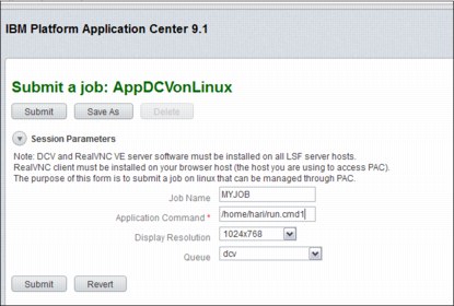
Figure 7-15 Submitting a new job to run a 3D application using DCV on Linux
After the user submits the form, PAC requests LSF to allocate an interactive session to use DCV. Initially, the jobs are assigned the status Pending if an interactive session is not available. The job status currently shows that the job is waiting for the interactive session.
After the hardware resource is properly allocated for the job, the status changes to Running as shown in Figure 7-16.

Figure 7-16 Clicking Visualize activates the interactive session
The progress of these requests can be monitored by clicking the jobs tab on the left side of the window. When the interactive session is allocated, a new status icon Visualize is displayed as shown in Figure 7-16. When the user clicks this button, session information is downloaded to the workstation and the user is prompted to start a real-VNC session and provide credentials for authentication.
Figure 7-17 shows the process to get the remote session started.

Figure 7-17 Session downloads session information and performs user authentication
After the user session is authenticated, PAC starts an ANSYS Workbench session like the one shown in Figure 7-18. From this point ANSYS users can work with ANSYS Fluent and ANSYS Mechanical. Because both ANSYS Fluent and ANSYS Mechanical use OpenGL calls for graphics, DCV intercepts these calls and runs rendering operations on the server, then compresses the bitmaps and transfers them to the real-VNC client on the user workstation. If the session disconnects, PAC does not end the session. The session can be reconnected starting from the step in Figure 7-16 on page 164 by selecting the job in progress and clicking Visualize.
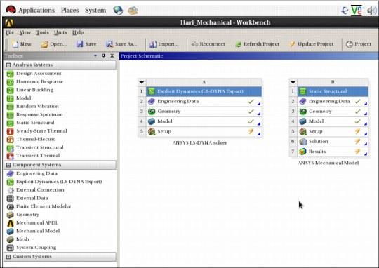
Figure 7-18 PAC automatically starts the ANSYS Workbench running on the backend
Figure 7-19 demonstrates a user working on ANSYS Mechanical through the remote desktop connection that is provided by the engineering cloud solution.

Figure 7-19 User interacts with ANSYS Fluent and ANSYS Mechanical through Workbench
After the user completes the graphics operations on the 3D models, the next step is to submit the solver jobs in batch mode to LSF to be scheduled on the back-end cluster. There are two ways that this can be accomplished:
•ANSYS Workbench uses a tool called Remote Simulation Manager (RSM) through which ANSYS Fluent and ANSYS Mechanical jobs can be submitted to an LSF cluster.
•After the input data sets are prepared, the two application templates, ANSYS Fluent and ANSYS Mechanical, can be used to submit the batch jobs outside ANSYS Workbench.
Method #2: EoD
The process of submitting a request for interactive session that uses Exceed onDemand for remote visualization is similar to DCV. However, EoD is able to provide two different deployment models.
Direct server-side rendering
Figure 7-20 shows the Exceed onDemand 3D direct server-side rendering.

Figure 7-20 Exceed onDemand 3D: Direct server-side rendering
Indirect server-side rendering
Using Exceed onDemand allows you to run more than one CAD session per server supporting applications running on IBM AIX and Windows. Figure 7-21 shows Exceed onDemand 3D indirect Server Side Rendering with application server on Windows.

Figure 7-21 Desktop cloud architecture using KVM and EoD
Workflow
After the user submits the EoD form, PAC requests LSF to allocate an interactive session to use EoD (Figure 7-22). Initially, the jobs are assigned the status Pending if an interactive session is not available.

Figure 7-22 Submitting an EoD job on PAC
After the hardware resource is properly allocated for the job, the status moves to the Running status as shown in Figure 7-23. The progress of these requests can be monitored by clicking the jobs tab on the left side of the window.

Figure 7-23 Job running
When the interactive session is allocated, a new status icon Visualize is displayed. When the user clicks this button, session information is made available in the form of a EoD file that can be started in the local notebook, provide that the user has installed the EoD client component. The user is prompted to start a EoD session and provide credentials for authentication. Figure 7-24 shows the process to get the remote session started.

Figure 7-24 Starting the EoD connection
After the session is connected, the EoD client runs on the background and a new icon is displayed on the taskbar (in this case, of Windows) as shown in Figure 7-25.
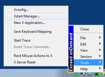
Figure 7-25 EoD menu on the taskbar
Click Tools → Xstart Manager to start a manager to select the appropriate Xstart file to run an ANSYS remote session. In the example environment, this is an ANSYS.xs file as shown in Figure 7-26.

Figure 7-26 Starting by using EoD client
The Xstart file has a list of commands that can be passed as session parameters. Figure 7-27 shows the command used to start a session in the example environment.

Figure 7-27 Starting script for ANSYS
After the user session is authenticated, EoD starts an ANSYS Workbench session such as the one illustrated in Figure 7-28. If the session disconnects, it can be reconnected by running the EoD provided by PAC.
Figure 7-28 EoD virtualized session running ANSYS Workbench on the server side
Figure 7-29 shows the work on a mechanical model.
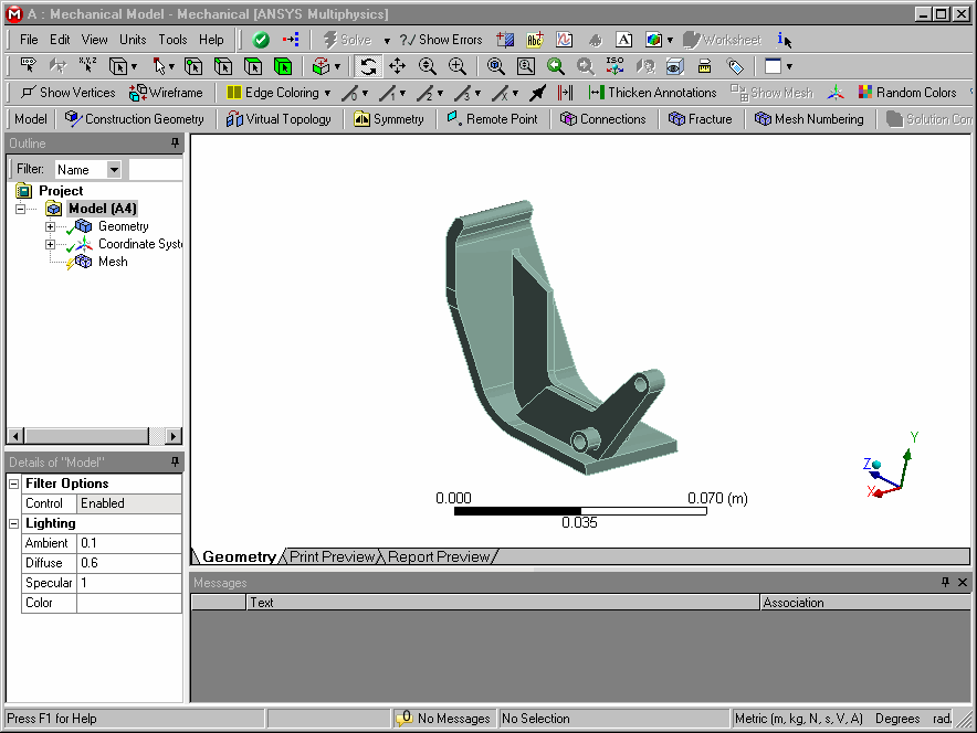
Figure 7-29 Working on a mechanical model
Remote collaboration
In a large globally dispersed enterprise, disperse the engineering 3D cloud deployment across the globe just like the engineering users. In other words, if you have multiple engineers in Tokyo, multiple engineers in Detroit, and multiple engineers in Berlin, consider building separate engineering 3D clouds in Tokyo, Detroit, and Berlin. These globally dispersed engineering clouds can (and should) be connected, and can even serve as a failover for the other cloud sites. In this case, the dispersed engineers get the best response and least network issues when using their local engineering cloud. Collaboration can still take place on a global basis, but distant collaborators might see some hesitation in model movement when in collaboration mode with an engineer in another location.
Scalability
Currently the upper limits of scalability of the Engineering 3D Cloud solution are unknown. The network characteristics of the client considering this solution are most likely the primary limiting factor for upward scalability. Because TCP/IP is used as the transport mechanism for the graphics images, network bandwidth and client network traffic must also be considered.
..................Content has been hidden....................
You can't read the all page of ebook, please click here login for view all page.