
Appendix C. Calibration Patterns
Calibration Patterns Used by OpenCV
There are many different kinds of calibration patterns. Each pattern or marker could be used in a calibration procedure or just to find the 3D pose of that marker. Figures C-1 through C-7 show seven different patterns or markers.

Figure C-1. Chessboard pattern (9 × 6 corners) for camera calibration or pose. This pattern can be used with the standard calibration technique described in Chapter 18, or in the camera calibration tutorial available online at opencv.org

Figure C-2. Circular features calibration or pose pattern. For this we can use the standard calibration technique described in this book or in tutorial_camera_calibration.html online using the findCirclesGrid() function

Figure C-3. Random pattern for calibration or pose. You can find an example of how to use this pattern by following the code in .../opencv_contrib/modules/ccalib/samples/random_pattern_calibration.cpp

Figure C-4. ArUco board for calibration or pose. See the “Calibration with ArUco and ChArUco” tutorial online at opencv.org for how to detect and calibrate with this board

Figure C-5. ChArUco board for calibration or pose; see the “Calibration with ArUco and ChArUco” tutorial online for how to detect and calibrate with this board

Figure C-6. ArUco marker; see the “Detection of ArUco Markers” tutorial online for how to detect an ArUco marker
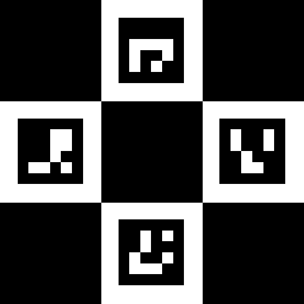
Figure C-7. ChArUco marker. See the “Detection of Diamond Markers” tutorial for how to detect a ChArUco marker. This is the diamond marker that appears on the front cover of this book
Figure C-7 shows a diamond ChArUco marker. If you build opencv_contrib modules with OpenCV, then in the associated bin directory, you can run the following to create this marker:
./example_aruco_create_diamond -bb=1
  -d=0 -sl=200 -ml=130 -ids=1,2,3,4
  -m=10 -si=true diamond.png
This code creates a diamond ChArUco marker where –bb=1 creates a marker border as wide as the marker bits; -d=0 creates a 4- × 4-bit marker (there are only four markers; we don’t need markers to be able to represent large numbers); -sl=200 draws a chessboard square of 200 × 200 pixels; –ml=130 draws the ArUco marker to be a 130 × 130-pixel square; -ids=1,2,3,4 just sets the ArUco markers to have coded values of 1, 2, 3, and 4, respectively; -m=10 puts a 10-pixel-wide border around the diamond marker; and –si=true tells the program to show the generated image onscreen. Finally, diamond.png is the name of the output image.
To detect this image and also the one on the cover of this book, use the following code:
./example_aruco_detect_diamonds -as=1.0 -ci=0 -d=0 -ml=130 -sl=200
This code runs a camera that finds the marker shown both on the cover and in Figure C-7. Once found, the code decodes the ArUco markers and shows detected boxes and corners on the image. This code should work on the marker on the front cover of the book.1 In this command line, -as=1.0 tells the program to autoscale the detection, –ci=0 tells the code to look for default system camera, -d=0 tells the code to use the 4 × 4 ArUco detection/decode library, and -ml=130 and –sl=200 give the relative sizes of the ArUco and checkerboard squares (since we are autoscaling, it needs only relative sizes).
1 It is left as a final exercise to the reader to use the detected marker on the cover of this book to create some interesting augmented reality overlay!