Creating a BIM model requires modeling in 3D. This is very different from using abstract 2D lines, arcs, and text to represent your design. To work with Revit and be able to build a BIM model, you need to understand how a building is built and how various building parts, ranging from the building mass down to furniture assemblies, are constructed at various scales. You need to know how various building elements interact with and depend on each other, what materials they are made of, and how they are constructed and assembled. To this end, Revit provides a set of tools that enable you to build your model and all the elements that go into the model. Understanding the principles of modeling in the context of Revit will be essential to your success as you move deeper into building information modeling.
This chapter is the first half of a description of the basic modeling principles that support the design process in Revit. In this chapter, you'll learn to:
Designers have a long tradition of modeling before building. This activity involves the use of pliable and tactile materials such as clay and wood to model designs smoothly. With these materials, form can be explored with ease, as designs iterate directly in our own hands. The use of software to model form has become a popular extension of this activity, and you only need to look so far as the latest animated film to see how far the technology has come.
Many software modeling tools are available that allow direct editing and intuitive shaping of form. Tools such as Autodesk Alias Design Studio, Autodesk Maya, Rhinoceros, Autodesk 3ds Max, Google SketchUp, and the latest release of AutoCAD allow you to create free-form conceptual shapes with relative ease. These tools are great for concept modeling, but they are not geared for a BIM approach to design and documentation. The elements created with these modelers are meshes, Non-Uniform Rational B-Spline (NURBS), ACIS solids, and other generic geometrical shapes that are used to represent walls, slabs, roofs, and windows. However, they do not have embedded intelligence or relationships among themselves or with other elements in the model. Further, they barely contain any metadata that can be quantified and analyzed. So, as it stands today, you will find great modelers that are not BIM and BIM applications that are not powerful modelers. One way that Revit approaches this problem is to allow importing of free-form geometry into the project and family environment, where it can then be used to derive walls, floors, and roofs. And while it is not as free-form as some other applications, Revit natively supports the creation of parametric 3D forms.
The entire modeling concept in Revit is founded on some basic class modeling forms—extrusions, revolves, sweeps, blends, and swept blends—and the combinations these can produce. The only place where this is not the case is the new set of Conceptual Design tools, introduced in this 2010 release of Revit. We will discuss these in greater detail later in the book in chapters 8 and 9.
Each of the five basic modeling techniques can produce either a positive or negative shape (solid or void). These shapes can be combined to create more complex forms. Each form is derived from 2D sketches that are drawn on work planes and then given a third dimension. We'll explore sketch-based forms in more detail in the next section.
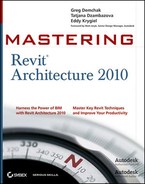
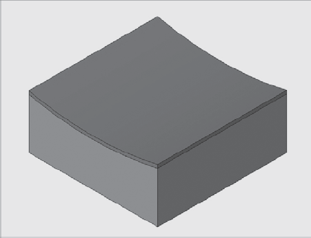
Figure 6.1 shows an example of what's possible using the modeling tools.

The majority of internal modeling techniques in Revit rely on an approach called sketch-based design, where you draw a shape in a special Sketch mode by creating 2D lines that then generate 3D forms. When you model most Revit elements, you enter a mode in which the entire model is grayed out and not selectable, so focus is placed on the sketch, which is represented in strong magenta lines. Once you've defined your shapes by creating closed loops of lines, you click Finish Sketch, and the geometry is generated. This Sketch mode is used throughout Revit, so you should get acquainted with its behavior early on.
For example, the Floor, Roof, Ceiling, Stair, and Railing tools require you to first sketch 2D shapes and then generate the form by "finishing the sketch." Revit then applies a thickness or other element-specific property to the sketch, based on the element type. Even walls have an underlying sketch, but in the case of walls, this is a sketch that can be edited in elevation, not plan view, as is the case with the rest of the elements (Figure 6.2). To edit the elevation of a wall, select the wall in an elevation or 3D view and click the Edit Profile button in the Modify Wall panel of the Modify tab. Note that this tool only applies to linear walls.
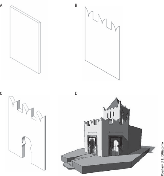
Figure 6.2. Moorish architectural example: (A) Standard straight rectangle shaped wall; (B) elevation sketch of that wall changed to the desired shape using simple lines; (C) wall shape result achieved by simple editing of the sketch in elevation; (D) the wall used in a building.
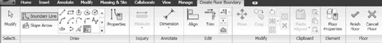
One of the first places you'll encounter sketch-based modeling is with the Floor and Roof tools. When you initiate either of these tools, you are instantly placed in Sketch mode. The Ribbon changes, indicating the new mode (Figure 6.3), and you see a set of tools specific to the task of creating 2D sketch lines and creating lines with relationships to other model elements.
For example, you can either draw lines freely using the Line tool in Draw panel, or use the Pick Walls tool from the same panel, which generates the floor or roof sketch lines when you pick on walls. When using the pick walls method, you create an explicit relationship between the floor or roof sketch and the walls. As a result, when walls move, the sketch (and thus the floor or the roof made of it) adapts and updates with the walls.
There are a few important rules you must apply when creating a sketch so that it is valid:
The sketch has to form a closed loop of lines, and the lines have to be perfectly trimmed at the ends. You cannot have gaps or overlapping lines in the sketch. Whenever a sketch is not complete or has overlaps, Revit will indicate that something is wrong with an error message and you will not be able to finish the sketch until you fix and clean it up.
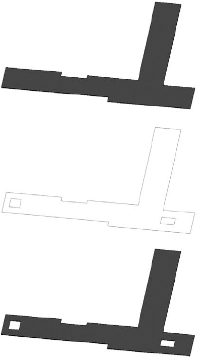
When creating certain types of elements, you are allowed to sketch more than one closed loop within or outside of the same sketch—this is fine as long as the two loops do not intersect. If one loop of lines is within the boundaries of the other, it creates an opening in the outer shape (Figure 6.4).
If you were to draw another loop within those openings, it would be positive and create another solid piece of floor of the same type. Here's the logic behind loops: one is positive, the next one within it is negative, and the next one within it is positive (Figure 6.5).

Here are some rules of thumb you will need to follow when sketching:
To edit a sketch, you must be in a view that is parallel to the sketch or a 3D view. For example, it is not logical to edit the sketch of a wall profile in a plan view as you would not be able to see the sketch in a way that is relevant. If you attempt to do this in plan view, Revit alerts you and proposes other views in which you can execute the task. The same goes for a floor—only in plan or 3D will you be able to edit the sketch.
Sketch mode cannot be activated in perspective (camera) views. If you select a wall or any other element and want to edit its shape but cannot find the Edit button on the Options bar, you are in camera view. Switch to an axonometric, 3D, or any other view in which the sketch makes sense to edit.
Reference planes, reference lines, levels, work planes... what are they? This section delves into each of these topics. First, to master modeling techniques in Revit, you need to understand the concept of a work plane.
The work plane is a 3D plane that you sketch on. For example, when you are in a plan view and start sketching a floor, the work plane is set to the level associated with the plan view you are working in. The majority of views in Revit (plans, 3D views, or views set in the family templates) have predefined work planes set automatically when they are created. Views such as sections and elevations require you to manually pick a work plane in order to add 3D elements to those views. In some cases, as with placing windows or doors in an elevation view, this is done implicitly—the cursor locates planes (walls) automatically.
A work plane can be understood as a surface on which you draw or place something. Imagine you are holding a marker in your hand and have a space in front of you. Can you draw with the marker in the space? No. You need a piece of paper, glass, wall—some kind of a surface to draw on. So, a work plane defines a surface on which you can build geometry. You can define a work plane by drawing a reference plane, picking a face from an existing element, or using an existing level (datum) as a reference.
Figure 6.6 illustrates the work plane. There are a few simple rules you must follow when using a work plane:
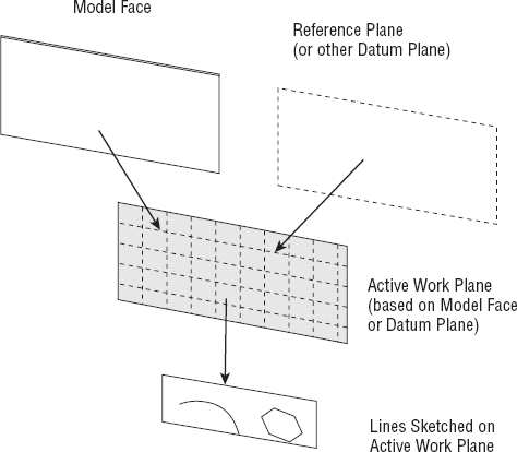
The work plane is set by selecting a reference plane/reference line; a datum plane (like a level or grid); or a planar face of a model element. Often it is preset and you do not need to explicitly set it.
Many elements in Revit use the active work plane to know where to sketch or place objects. (Some objects are limited to only horizontal or vertical work planes.)
The work plane is also used when you are modifying objects. When you drag or move an object, it is typically constrained to that plane.
When you set the work plane to be based on other selectable elements, it creates a dependency, or relationship, to the underlying reference you selected. If the underlying object is moved, the work plane is moved to stay aligned to it. Any objects created on the work plane will also update.
Let's take a closer look at the types of work planes available in Revit.
Levels are horizontal work planes that define the levels in a building and can also be used to denote important horizontal references in a building (such as attic height). Levels are only created and visible in section or elevation views. The only exception to this is when creating a new Conceptual Mass in the Family Editor—there levels are represented in a 3D view. Each level typically has a corresponding floor plan view associated with it, although it is possible to make levels with no associated floor plan. For example, a level may define the Top of Steel in a building section, but there is no need to have a floor plan view of that level. For that case, you can create levels without plans by clearing the option Make Plan View on the Options bar when the Level tool is activated. This creates a level that appears black and white rather than blue, indicating that there is no hyperlinked view.
Note that when you create new levels using the Copy tool from the Modify panel, the newly created levels are black and white (unlike the levels that are drawn using the Level tool and that are represented with a blue symbol). This change in color indicates that this level has not generated a new floor plan that is associated with that level as the Level tool does usually. If you do need a corresponding floor plan associated with that level, you can use the Plan Views tool in the Create panel of the View tab. You will then be able to add a plan view associated with any existing level in the project.
When you place families, they automatically become associated with the level they are placed on. Walls, roofs, and stairs all have top and bottom constraints to levels. This guarantees that when the level changes height, so too will all the elements on that level. All sketch-based families such as floors, roofs, ceilings, and stairs are also associated with at least one level. This, however, means as well that if you delete a level, all the elements associated with that level will also be deleted! So use caution when deleting levels; it's not just a drawing that you are deleting!
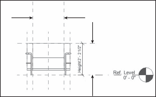
Grids are vertical planes used as standard references in the construction industry for creating location grids on the site as well as a communication reference between the building participants. These construction datums are used to accurately define locations for elements such as columns and beams or positions of main structural walls or the exterior shell. You can associate elements with the grids so that when the grid system changes, it controls the position of the associated elements. A good example for that would be columns associated with grid intersections. As with a level, when a grid is moved, associated elements move with the grid (Figure 6.7). Grids and levels (datum) only show up in views that intersect the datum.
Reference planes are used to drive other geometry. They are planes that exist in 3D space that other elements can be attached to. While not visible in 3D views, they can be seen when perpendicular to plan, section, and elevations and are represented as green dashed lines. Similar to levels and grids, these lines are not view specific and will appear in all perpendicular plans, sections, and elevations. Even though reference planes look and feel like ordinary lines, they are very different. Think of them as symbolic representations of infinite planes. The ends of reference planes are selectable and you can drag them to make them longer, but you will not be able to rotate the end of a reference plane freely as you can with lines.
Reference planes are the essence of parametric content creation in the Family Editor, as they are used to create the parametric skeleton to which geometry is then attached and allowed to vary. The reference planes in a family are what you dimension to when they are loaded into a project—not the geometry.
Giving the reference planes various states also affects how other elements relate to the family. A reference plane can be set as not a reference, weak, or strong, and it can be defined as a reference for the left, right, front, bottom, back, or center position. The selection of these options is important in the Family Editor environment, as they define references for snapping. When you have two crossing references set as Strong, they define the insertion point of an element when you place it in the project environment. The origin must be further defined in the instance properties of the crossing reference planes by selecting "Defines Origin."
In Figure 6.8, the two centrally positioned strong references define the insertion point of the element. The weak references serve only as secondary snaps.

Figure 6.8. The insertion point of the desk is the point of the two crossing references that has been identified as "Defines Origin."
In a project, reference planes can be used to drive geometry (see Figure 6.9).
Reference lines were designed mostly for use in the Family Editor to overcome the limitation of the reference planes and their inability to define constraints that reference a point, direction, and angle. Unlike with reference planes, the start and end points of a reference line can be referenced and used for dimensioning. A popular use of a reference line is to define door swing opening angles by creating an angular relationship between the door leaf position and the closed state of the door leaf. This will let the user set any angle of door opening later in the project. Other differences between reference lines and reference planes are that you cannot name the reference lines and you can only select them graphically.
Reference lines define four work planes—the two along the axis of the reference line and the third and fourth planes that are perpendicular to each of the line segments (see Figure 6.10).

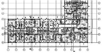
As previously mentioned, reference planes extend in all views. Once drawn in one view, they will appear in every view that shows the area where they are created. But that is not necessarily what you always need. Let's say your project has a base of five floors of conference area with a 30-story hotel above (like the model shown in Figure 6.11). It's likely you'll have separate structural bays for each part of the building. You don't need to see all grid lines of the conferencing base in the hotel tower, and vice versa.

Figure 6.11. (A) This building consists of two main volumes, a low volume with conference usage and a tower with hotel use. These two volumes use separate grid systems, and thus two different scope boxes are created to control the visibility of the separate grids. (B) Grid element properties indicate the scope box to which the grid belongs.
The Scope Box tool will help you deal with this issue and allow you to limit the range in which reference planes (grid lines, levels, and reference lines) extend and appear. In our example shown in Figure 6.11, the building has a base shape that accommodates a conference center and a tower in which a hotel is situated. They have very different configurations and need different grid systems. The thing to do is to draw two separate scope boxes around those two entities, using the Scope Box tool allocated in the Create panel of the View menu. Then the grids of each of those two parts of the building need to be assigned to the appropriate scope box (the grid of the base to the Conference scope box and the grid of the tower to the Hotel scope box).
Scope boxes are visible in 3D views—although not in camera (perspective) views—and you can easily manipulate their extents at any time directly using the grip controls. Assigning gridlines or other datums to a scope box is easy: select the gridlines, and in the Instance Properties dialog box, choose the Scope Box parameter and select the scope box where the datums should belong. Figure 6.11 shows the Instance Properties dialog box for the gridlines and the associated scope box.
Before moving on to look at using work planes in practice, let's take a moment to summarize the basic theory.

- Name
This option displays available levels, grids, and named reference planes. Note that only reference planes to which you have explicitly assigned names appear in this list. To name a reference plane, use the element properties of the reference plane.
- Pick a Plane
This option allows you to select a plane interactively in the model. The selection is visual and you need to click on a reference plane, wall face, or faces of an element. Figure 6.13 shows how different an extruded shape will be when selecting different planes on which to sketch and create a void extrusion. The face of the element that's marked darker represents which side of the element was set as a work plane.

Figure 6.13. The same mass and the same 2D shape extruded as a hole. In (A) the extrusion shape is drawn on the front face of the mass; in (B) the extrusion is drawn on the back face of the mass.
- Pick a Line and Use the Work Plane It Was Sketched In
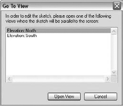
With this option, Revit converts the work plane on which the line was created into the active work plane. When you select a work plane that is perpendicular to your current view, Revit opens a new Go to View dialog box that gives you options to select a view in which the chosen work plane can be worked on (Figure 6.14).
If you are not sure where your active work plane is, click the Show button in the Work Plane panel.
Revit will let you rotate a work plane grid by clicking on it and selecting Rotate from the Modify panel. This in turn affects how new elements will be placed on that work plane. You can also align elements to the work plane grid, and lines will snap to the grid (Figure 6.16).
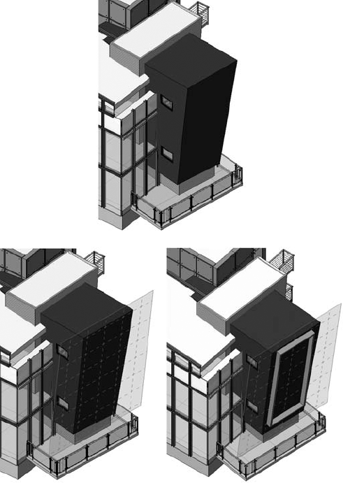

Figure 6.16. When the work plane grid is rotated, new elements placed on the work plane will also be rotated.
To change the work plane an element is already associated with, select the element, and then click the Edit Work Plane button in the Work Plane panel of the Modify tab and select another work plane using one of the methods in the dialog box.
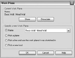
To dissociate an element from a work plane, first select the element. Next, click the Edit Work Plane button in the Work Plane panel to display the dialog box shown in Figure 6.17, and click the Dissociate button. The element will then be free to move anywhere in the model. Note that this option is only available for work plane-based families.
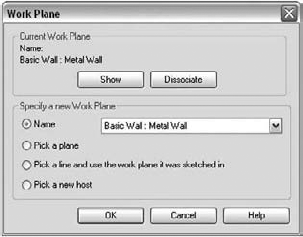
Figure 6.17. The Work Plane dialog box allows you to set the work plane of an element or dissociate it from its work plane.
Once you have dissociated an element from its work plane, you will notice that the value for the work plane instance parameter (located in Element Properties) will be set to <not associated>.
Most importantly, you will notice that the element is free from constraints and is free to be moved in any 3D direction.
To rehost elements from one host (wall, floor, or roof, for example) to another, you can use the Pick New Host button from the same Work Plane panel when an element is selected. This allows you to select a new host to place the element. With this tool, you can choose any new host—it does not have to be in the same plane as the original. For example, you can select a window in one wall, click the Pick New Host button, and then choose a new wall for the window.
Figure 6.18 shows an extruded shape originally created on a horizontal work plane. Using the Pick New Host tool, you can place the form on any surface in the model.
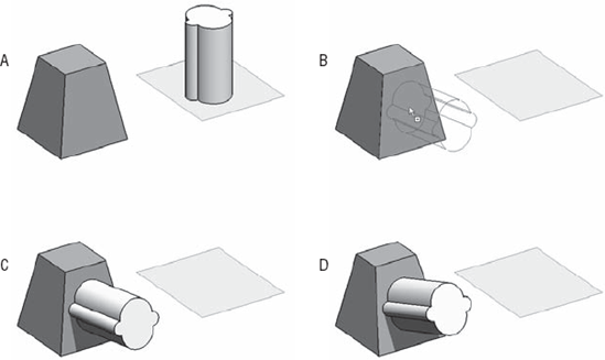
Figure 6.18. (A) Original condition; (B) desired repositioning of the curved element; (C) the element is rehosted and a relationship between the two elements has been created; (D) the host changed its geometry and the hosted elements follow the change.
Here are two versions of the same building, with roofs that use the same sketch profile but are drawn on two different work planes. Image A shows a roof by extrusion sketched on a work plane parallel to the exterior wall; B shows the same roof sketched on a work plane rotated 45 degrees with respect to the exterior wall. Notice the difference!

Creating a Roof by Extrusion (Default Work Plane)
Take the following steps to see for yourself how version A was created:
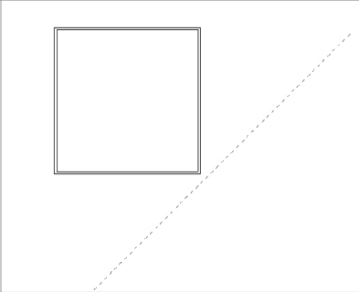
Draw four walls in plan view in the shape of a square.
On the Work Plane panel of the Home tab, select the Reference Plane tool and draw a reference plane parallel to the south wall:
Pick the reference plane and open its instance properties. Give it the name Front Roof Plane.
On the Create panel of the Home tab, select the Roof tool and select Roof by Extrusion. You will be prompted to select a work plane.
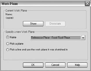
From the Name list, select the named reference plane you just drew and named. You'll be asked to open a view to begin sketching. Choose the south elevation.
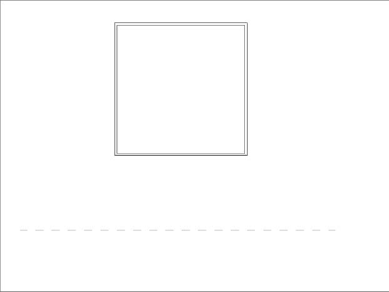
Sketch a roof in arc shape, as shown here, and finish the sketch:

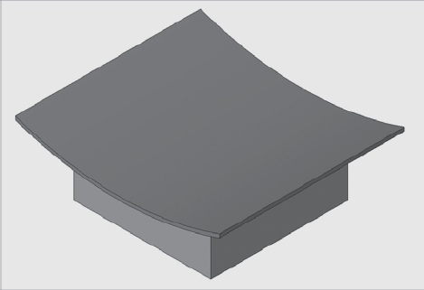
Go to the default 3D view and, using the blue arrows, adjust the length of the roof to make sure it extends beyond the exterior walls, as shown here:

While still in the 3D view, select all the walls. Click the Top/Base: Attach button in the Modify Walls panel of the Modify tab and then select the roof to attach the walls to the roof. The resulting building should look something like this:
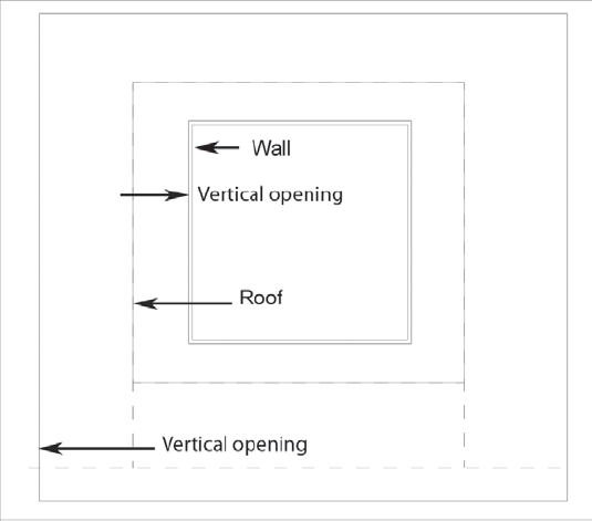
To cut the roof so that it ends at the edge of the exterior walls, switch to plan view (Level 2 or Site plan), select the roof, and select the option Vertical Opening in the Modify Roof panel. This allows you to cut off the extruded roof exactly at the edge of the building, regardless of its shape. In this example, draw two rectangles (the location is indicated in the following figure with Vertical opening) that cut the roof up to the face of the walls.
After applying the two sketches using the Vertical Opening tool, the final result for the first roof should look like this:
Creating Version B: A Roof Using a 45-Degree Work Plane as a Reference
To obtain the second roof (B) shown at the beginning of this section, repeat all the previous steps, but draw the reference plane at a 45-degree angle to the building, as shown here. Remember to give the reference plane a different name in its Instance Properties dialog box.
The finished roof looks like this:

- Understand the basics of modeling with Revit.
Modeling with software is an extension of the traditional art of modeling with the hands. Free-form 3D modeling tools are not designed with BIM workflows in mind, but it is still possible to import shapes into Revit for downstream use. At the same time, Revit provides some basic tools for 3D design, and you should familiarize yourself with these.
- Master It
Tools such as Autodesk Alias Design Studio, Rhinoceros, Autodesk 3ds Max, Autodesk Maya, SketchUp, and AutoCAD 2010 allow you to create free-form shapes with relative ease. How does Revit let you take advantage of such shapes?
- Understand sketch-based design.
Sketch-based design allows you to define some basic parameters and shapes in Sketch mode within Revit.
- Master it
Revit uses a 2D sketch-based approach to modeling. What modeling elements in Revit use this 2D sketch principle to generate their form?
- Understand work planes, levels, grids, reference planes, and reference lines.
Using these tools gives you the ability to better control your model and your design by applying and controlling parameters.
- Master It
In order to sketch a form, the form must reside on a work plane. How do you define and visualize the work plane in Revit?