One of the many advantages of working with BIM models is that you can produce perspective views of your model as often as you wish—and it takes only a few mouse clicks to do it. Think about how tedious the process of creating 3D axonometric or perspective drawings was, whether you did so manually or used CAD drafting tools. Perspective views are greatly appreciated by owners as they visually communicate the intent of the design better than any other representation.
If you open a Revit project that has been in development for a while, you'll find dozens of perspective views. Although most of these views will never make it onto sheets, it's becoming standard practice to include one or two exterior perspectives on the cover sheet. Sheets aside, these views are critical for understanding your design from a human point of view and are used consistently for client meetings and internally when fleshing out a design. In many cases, a hidden line perspective view with shadows turned on provides an excellent graphical representation of your model. You can also take the visualization up a notch and produce photorealistic renderings without having to be a rendering guru.
In this chapter, you'll learn to:
Create perspective views
Create photorealistic renderings
Create animated walkthroughs
Export the 3D model for use in other applications


For exterior views, start by placing the camera approximately 100′ (30m) from where you intend to aim the camera. Placing the camera too close to the model will often put you right up against a wall, and you'll have to readjust the camera to see more of the model.
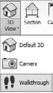
When you activate the Camera tool, you first establish the eye position and then set the target. It's a simple two-click operation, and the next thing you know, you're taken directly to the camera view, looking at a perspective of your model. Revit puts the camera at eye level by default when you place a new camera in a plan view. This is usually fine, but you're free to adjust the camera dynamically or by manipulating the elevation of the eye and target levels through the element properties of the camera.
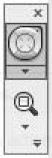

The walkthrough options allow you to walk, look, and move the camera up and down. To adjust the focal length of the camera (zoom the camera in or out without moving the camera), click the small arrow at the bottom right of the SteeringWheel, and choose Increase/Decrease Focal Length (Figure 16.2). It acts as if you're zooming your lens in and out, while keeping the camera stationary. (Don't confuse this with walking the camera closer to the building.)
To see a camera from the context of 2D or 3D axonometric views, right-click the 3D view name in the Project Browser and choose Show Camera. The camera appears in all views as a camera icon with the view extents shows as red lines (Figure 16.3), so you can visualize where the camera is relative to your model. At this point, the camera is selected, so you can move it to a new location, and the view updates automatically to reflect the change. You can also adjust the target position in this mode. Just be careful where you click—clicking anything else (including nothing) deselects the camera, which causes it to disappear.

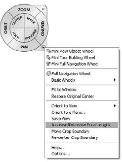
As you saw when we discussed elevations, overriding the edges of elements can help make a drawing more legible and graphically clear. In addition to using the Linework tool, you can use a more dynamic feature built into Revit, which accounts for the fact that perspective views are likely to be spun around and reoriented. From the shadow icon in the view frame control tools you can access the Graphic Display Options dialog box. Toward the bottom is a control that lets you set a line style called Silhouette Style.
By choosing a line style with a thicker line weight, you'll see the effect of this feature. The line style isn't applied to specific edges of the model but instead is dynamically redrawn depending on the camera's point of view. Revit applies the line style to the outer edges of elements visible in the view, giving the model a bold outline. The effect can be subtle but elegant, as shown in Figure 16.4. If the effect is too subtle, try making the view larger (the default is a 6″ × 4.5″ view) and making a new line style with a heavier line weight.

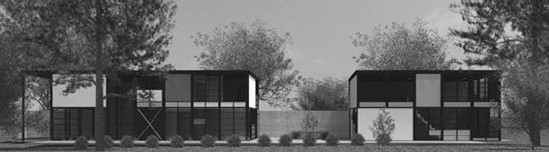
Revit provides an integrated rendering workflow that delivers stunning photorealistic renderings. The rendering engine works hand in hand with a library of rendering materials custom-designed for architectural visualizations. With Revit's rendering features, you can assign some materials, set up a camera, click Render, and get some great results right out of the box (Figure 16.5).
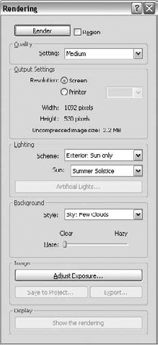
To render a perspective view, click the teapot icon in the view frame controls at bottom of the view. This launches the Rendering dialog box (Figure 16.6), where you set all the parameters for the rendering, such as quality, output, lighting, background, and exposure settings.
Let's look at this dialog box in more detail, as each setting will affect how the rendering looks.
The first set of rendering options is the Quality settings (Figure 16.7). These affect the overall quality and, perhaps more important, the time it takes to render the view. The higher you go in quality, the longer the rendering time will be. We recommend rendering at draft or low quality initially and going to higher quality only after you have validated the material and scene selection assigned to the model.

The settings have been tuned for optimal results, but if you want to tinker under the hood, so to speak, you can select the Edit... option located at the bottom of the dropdown list. This opens the Render Quality Settings dialog box (shown in Figure 16.8), where you can see all the variables that affect the rendering quality. Any change you make to these settings is stored in the file as a Custom (view specific) setting. This prevents your changing any of the factory presets but at the same time gives you total flexibility to go beyond what has been preset.
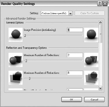
Figure 16.8. To see all the parameters that affect quality settings, open the Render Quality Settings dialog box.
The images on the right and left sides of each setting are visual cues to help you understand the effect of the setting. To see what each factory preset does, use the Setting drop-down list at the top of the dialog box. To edit these settings, click the Copy to Custom button. This copies all the settings into the editable custom setting and allows you to refine the settings.
The Output Settings area allows you to set the resolution of the image being rendered. The default is Screen; the size of the image (width and height) is measured in pixels, as shown in Figure 16.9A. Choosing Printer allows you to select from some standard DPI settings. The Width and Height values update automatically for you, giving you an idea of the final output size and the Uncompressed Image Size, which is the size of the file if saved as an uncompressed TIFF (see Figure 16.9B).

Unless you are ready to send the rendering off for printing (150 dpi draft or 300 dpi finished print quality is recommended), keep the resolution at Screen (72 dpi). This will improve the speed of the renderings without compromising overall quality.
The Lighting options (Figure 16.10) set exposure levels, let you select what kind of lighting to use, and establish the sun position. The options are self-explanatory: just match the setting with the kind of camera you've set up. Are you outside? Inside? Do you want to see the effect of sun, just artificial lights, or both?
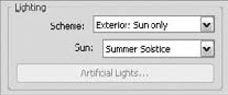
The sun position is enabled for any scheme that includes the sun as a light source. The list includes sun settings. To access and edit these settings, click the Edit option at the bottom of the list. You can also access this same list by choosing Settings

When you choose a setting that includes artificial lights, Revit calculates and renders light that emits from lighting fixtures in the view. All the lighting fixtures that ship with Revit are designed to cast light when rendered. For lighting fixtures that were previously placed in earlier versions (pre 2009) of the software, you'll need to manually upgrade the fixture. This is not as hard as it sounds; simply select the fixture, click the Edit Family button in the contextual tab, and then load it back into the project once it opens in the Family Editor.
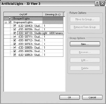
By default, Revit calculates all the lighting fixtures in your model, which can lead to extra-long rendering times. To improve speed, click the Light Fixtures button in the Rendering dialog box. This opens the Artificial Light dialog box, where you can choose whether fixtures will cast light. You'll see a list of all lights in the project in this dialog box, and you can turn them on or off.
What if you want to make an interior rendering in a real project? To improve performance, you want to render only lights that are visible in the view. In the Rendering dialog box, click the Artificial Lights button. Whenever you select lights in the resulting dialog box (Figure 16.12), they are selected in the model (turning red), which makes it easy to know which lights are on or off.
In Figure 16.13, we created a new group by clicking the New button and naming the group First Floor Lights. We moved lights to the group by clicking on each light to see if it highlighted in the view. When the light did highlight, we clicked the Move to Group button to move the light into the First Floor Lights group. Then, to improve rendering performance, all we had to do was clear the Ungrouped Lights option to turn off all the lights not in our view.
You can group lights together from any view in Revit when a lighting fixture is selected. To do so, select a fixture and check the Options bar. You'll have the option to assign the light to an existing group, ungroup it, or create a new group by choosing Edit/New, as shown in Figure 16.14.
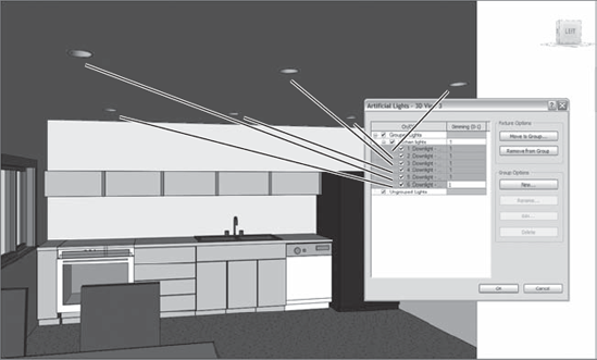
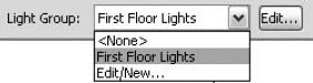
Figure 16.14. When a fixture is selected, the option to add it to a group is available in the Options bar.
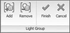
You can also choose to edit the group (if the light is in a group) by clicking the Edit button. This changes the model to halftone and shows all lights in the group as green. A floating toolbar appears that allows you to select light fixtures and either add or remove them from the group (see Figure 16.15).
The Background settings (Figure 16.16) help give your model some context by using a sky, a sky with cloud cover, or color. The sky in Revit is tied directly to the Sun and Shadows settings and will accurately color the sky based on time, date, and place. As you get toward dawn or dusk, the sky will change color to reflect this. You won't need to manually specify any color gradients. If you intend to use images in your background with a tool like Photoshop, you'll be glad to know that the background is saved as its own channel when images are exported as PNG files. This means you can use whatever background image you want and get a clean, perfectly blended look. This also allows you to position and edit your background graphics in Photoshop, where you have total control.
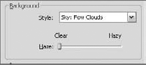
To add some clouds to the background, choose from the options available in the Style drop-down menu. Clouds will appear wispy and subtle when using these options. If you want strong, high-contrast clouds, add them in postprocessing by doctoring your images in an image-editing program—just be sure to export to PNG. You can also use a single color for a background.
Once you've chosen the quality, output, and lighting scheme, you're ready to render the view. Click the Render button and Revit will start the rendering process. Actually, a new process starts that is independent of Revit, so if the rendering were to get stuck or crash, you could stop the rendering process without having to stop Revit. You can see this in Windows Task Manager as fbxooprender.exe (see Figure 16.17).

A progress dialog box will also appear.
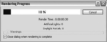
Here you will see how long the rendering is taking, how many artificial lights and daylight portals are being calculated, and if any warnings are encountered during the rendering process. An example of a warning would be if the path to images used for rendering were no longer intact. To cancel the rendering at any time, just click the Cancel button, and confirm you want to stop.
When you choose a lighting scheme, Revit automatically determines some exposure settings for you. You can adjust these either before or after running a rendering. Click the Adjust Exposure button to open the Exposure Control dialog box, shown in Figure 16.18.

Figure 16.18. The Exposure Control dialog box gives you a series of settings for adjusting the exposure.
After the rendering is complete, you can change the values of these options. Click Apply to change the appearance of the image after the rendering is complete. For example, if the rendering seems too dark, try decreasing the Exposure Value setting. To return settings to factory defaults, click the Reset to Default button at top of the dialog box.
Once you've produced a rendering that you're happy with and want to keep, the Rendering dialog box gives you two options. You can either save the image in the project or export the image to disk. When saving to the project, the rendering is saved in the Rendering branch of the Project Browser and can be dragged onto sheets like any other view. When exporting, the image will be exported and not stored in the project environment. If you need to do some postprocessing with Photoshop, click the Export button. You can save the rendering in standard image formats (BMP, GIF, JPG, PNG, or TIF).
Revit's rendering materials are designed to convey characteristics of texture, color, reflectivity, and transparency that you'd expect to see in reality. An entire library of materials (branded as ProMaterials) was designed specifically for architectural visualizations. In this section you will learn about how to use the material library and how to create custom render appearances.
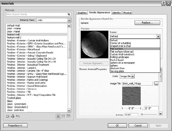
The Revit materials have an associated tab that contains information about how each material will look when rendered. This information is located in the Render Appearance tab in the Materials dialog box, shown in Figure 16.19.

If you're not satisfied with the default render appearances and need to manually assign new materials, the Replace button should be your first stop. Click that button to bring up the Render Appearance Library (Figure 16.20), where you can search for and assign render appearances.
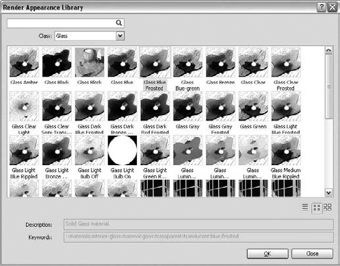
In this dialog box, you can search for materials by typing in the search field, or you can sort the materials using the Class drop-down list. Selecting a render appearance and clicking OK closes the dialog box and replaces your active material with a new render appearance. Consider using this library before making your own customized materials, as they have been carefully tuned to work well in Revit models.
Many good-looking materials use digital images that are scaled to match the building model. These images are often professionally produced and edited so as to not tile in an obvious manner when repeated over a surface in the model.
A hallmark of a bad image map is that you can see where each image begins to repeat. We don't recommend making your own texture maps, because the tiling effect is difficult to manipulate on your own. Go to a website such as www.turbosquid.com or do image searches for materials.
If you have your own high-quality images that you'd like to use when rendering, this is not a problem. Locate your material in the Materials list. To remap your image, choose the Color parameter and select Image File (Figure 16.21). This takes you to a dialog box where you can browse to your own image file.
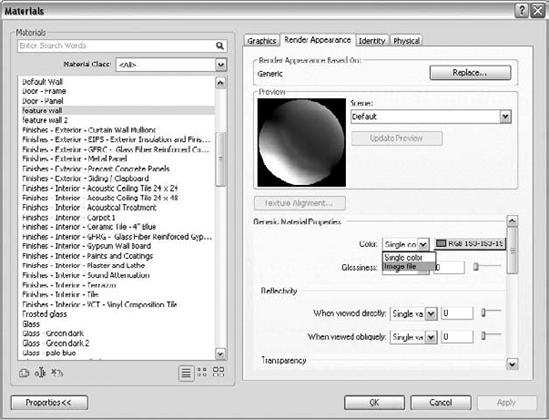
You'll then need to set the scale and change the preview to something more appropriate. Change the scale by typing in a value next to the image preview. This value sets up the repetition module for the image—relating a pixel-dimensioned image to a real-world scale. You can play with other parameters available in the generic render appearance, but for the most part, getting scale correct will be the most important task.
To change the preview, use the drop-down menu next to the preview swatch scene at the top (Figure 16.22). In this example, we are using a custom brick image and changing the preview to use the Flat Surface setting.
Adding people, cars, and trees to a rendering will give it a sense of scale and context. This technique is usually applied to give a rendered image a more realistic and human effect. This can be achieved by placing entourage and planting families into your model. When rendering a view, this content takes advantage of Rich Photorealistic Content (RPC) technology to show photographic images in the context of the rendering.
Note that any trees created pre-2009 Revit will not render. You'll need to load new trees and replace the old ones manually. To do so, load from the planting folder and select an RPC tree. Doing so will load many types, and you can choose from a list of RPC trees (Figure 16.23).
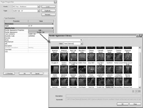
To replace trees quickly, use the Select All Instances option in the context menu when a tree is selected. This selects all instances of the tree and allows you to change the type to an RPC type. Be aware that the graphics will change, as the new RPC trees use a different mode of representation than previous versions of Revit. To see what RPC file is associated with a type, select the tree, open Instance Properties, select Edit Type, and click the Render Appearance parameter in the Type Properties dialog that opens. This opens a Render Appearance Library with all of the available RPC trees (Figure 16.24).

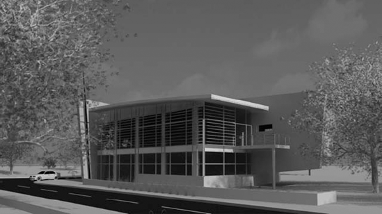
Once you have placed your trees, render the view, and you'll see the results (Figure 16.25).
Here are some guidelines for rendering efficiently.
Don't set the Quality settings to Best when iterating through material selections; doing so only slows down the time it takes to render. Keep Quality at Low or Medium until you're ready for a final pass.
Use a low screen resolution until you're ready to export a final image for printing.
Turn off lights that aren't visible in your view using the Artificial Lights dialog box. Group lights by floor if you are doing interior renderings of various floors in your model. This will speed up your renderings.
Adjust quality settings only if you absolutely have to. Changing one value could inadvertently slow down your renderings and return unnoticeable effects. All of Revit's presets were carefully calibrated and should do the trick.
Export rendered images to PNG in order to composite the image with background imagery.
Moving through a building in a virtual manner is a great way to experience a design before it gets built. Static images are nice, but it's becoming a common method to create animation sequences that showcase key aspects of the design. Revit provides tools for creating walkthrough sequences for the model, which you can then export as an AVI file.
To make a walkthrough in Revit, the process is as follows:
Once you've clicked the tool, you're put into a Sketch mode where each click creates a keyframe that lets you change the direction of the camera. Think about how a camera would move through or around a building. When you've finished sketching, click the Finish Walkthrough button on the Ribbon.

In this mode, you can edit the camera and path. The default setting allows you to step through each keyframe using the VCR-style controls located in the Modify Cameras contextual tab and adjust the camera direction in the view. You can edit the camera direction only at keyframes. To see what the camera sees, click the Open Walkthrough button. Keep stepping through keyframes and adjusting the camera. In the camera view, you can enable the SteeringWheel and change the direction the camera is looking just as you can in a 3D perspective view.

With the walkthrough view open, export the walkthrough to
.aviformat by using the Application Menu and choosing Export

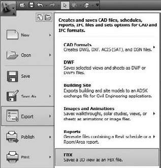
If you have established ways of working with vector or pixel-based artwork, you can always export Revit views and use them as backdrops for your artistry. From the application menu, choose Export. You'll find options to export CAD formats for DWG, DXF, DGN, and SAT. You can also export any view as an image file using the Export
Once you've made edits to the exports in applications such as Photoshop, Illustrator, or Piranesi, you can always re-import the artwork into Revit and place it on sheets with your other views.
For rendering purposes, you can export a Revit file to FBX format (Figure 16.27) and open it in 3ds Max (2009 or later). Even though Revit can create compelling renderings on its own, the ability to batch render as well as utilize render farms means that you'll be able to create renderings in minutes rather than hours when using 3ds Max. In addition to the geometry, the FBX file contains information about the materials in the model (Figure 16.28) and to which elements the materials are applied. This information is available only if you open the file with 3dS Max or 3dS Max Design 2009 or later.

- Create perspective views.
Design visualization is a key benefit to using Revit as a documentation solution. Being able to snap quick perspectives of your spaces and building forms can be critical to making good design decisions.
- Master It
Create a new perspective view showcasing a critical design feature. Use the Rendering dialog, lighting, and the materials dialog to complete the rendering.
- Create photorealistic renderings.
You know those signs that are put up at a site before and during construction—the ones with the nice rendering showing the final product? Well, you can generate those directly in Revit!
- Master It
You've been asked to produce an exterior rendering of a building. Can you do this in Revit? Can you tweak the results in Photoshop?
- Create animated walkthroughs.
Creating animated walkthroughs is an excellent way to visualize the spaces within the project, as walkthroughs are more dynamic than still renderings.
- Master It
You want to create a compelling animation showing an entry approach to the building. How would you do that with Revit?
- Export the 3D model for use in other applications.
Revit is an excellent application, but a variety of other tools are available that you might want to use for rendering, modeling, or other BIM features such as 3D printing.
- Master It
You've modeled your project in Revit and assigned materials, and now want to make an animation sequence with 3ds Max. What should you do?