
Chapter 21, "Moving from Design to Detailed Documentation," covered the transition from design to construction documentation. Now you will continue building your skills and learn some additional techniques for more detailed construction documentation. As your project experience grows, your library and detailing capacity within Revit will grow with it. This chapter is dedicated to tools and functionality that you can employ after you become comfortable with creating details in Revit. By building your library and knowledge of detailing workflows, you can cut down the time you spend detailing, leaving more time for design.
In this chapter, you'll learn to:
Create 3D details
Add detail components to 3D families
Reuse details from other Revit projects
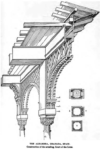
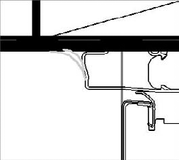
As building designs become increasingly complex and the construction industry continues to specialize its assembly methods, it has become imperative that information be communicated effectively between designer and contractor. A technique for showing construction assemblies that has an established place in the history of architectural representation is the use of 3D detail drawings (Figure 22.1) that show a sectional cut through the building in a 3D format (axonometric or perspective). This type of drawing is used to convey pragmatic detail and constructability information rather than having to create a multitude of 2D sections and elevations to demonstrate complex building details. In recent years, this documentation technique has fallen into disuse because it is difficult and time consuming to re-create axonometric details in a 2D CAD-based environment.
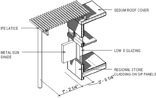
With Revit's 3D modeling capabilities, it is easy to create such 3D details. By using 3D views and the Orient to Other Views command, you can quickly generate 3D views that focus on a construction condition. These views can be used for constructability or to demonstrate critical building concepts. Figure 22.2 shows a detail of a sustainable solution employed on the Foundation project. In this sectional axonometric, we are able to demonstrate many of the green building concepts simultaneously while also showing dimensional depths of the sunshading and daylighting systems.
Creating these kinds of 3D details in Revit is quick and easy to do. There are two ways to do this:
Turn on the Section Box tool, and then adjust the section box to focus on your detail
Orient a 3D view to an existing view. This method adjusts a 3D view to resemble a chosen 2D view. You can then rotate the cropped 3D view to any new orientation. This method is much more practical than cropping the view manually because it is much faster to generate details and because the size of the detail condition is focused on an existing, pre-established scope
Take the following steps to enable the Section Box tool in a 3D view:

Open View Properties and enable the Section Box parameter. A large section box that surrounds the entire model will appear in the view. This is a 3D clipping box that allows you to cut the model from six directions.
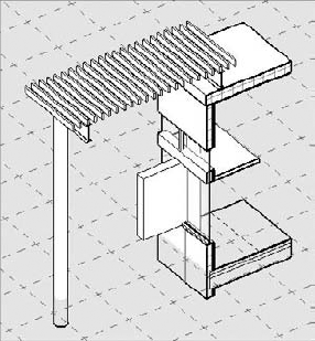
By clicking and dragging the blue arrows, you reduce the size of the box to a clip that represents the detail area you wish to indicate (Figure 22.3). Manipulating a section box can take a bit of trial and error, regardless of your experience with Revit. Later in this chapter, we'll discuss some ways to make this quicker and more accurate.

An alternative for creating a 3D detail is to orient the 3D view to an existing view. Do this by first creating a detail callout where needed, let's say in a wall section, as shown in Figure 22.4. Then, give the callout detail view a recognizable name by selecting the callout and editing its element properties. Call it Sunshade Detail. Having a recognizable name will make the detail easier to find later, as the number of details in a project can become quite large.

Now that we have established which detail we'd like to be able to rotate in 3D, let's create the new, 3D view:
After creating the callout, open the default (3D) view by selecting the 3D view icon from the toolbar. Right-click the ViewCube and choose View

Once you click OK, the 3D view reorients and appears in the form of a section—just like the detail callout. However, this is a 3D view. By orbiting this view (using either the ViewCube or combining Shift and the middle mouse button), you'll be able to visualize the sectional detail in 3D (Figure 22.6).

The crop boundaries of the 3D detail correlate to the boundaries of the callout, so there is no need to alter the section box as was the case with the first method of creating 3D details. The depth of the section box in this view is defined by the depth of the view you have used for orientation. You can edit the section box using the grip controls as you would any other section box. To hide the section box lines but keep it cutting the model, select it, right-click it, and choose Hide in View

Even if 3D details are much richer and clearer in information than 2D details, they still need annotations (dimensions, text notes) that add to the graphical explanation. To add dimensions to a 3D view, you first need to define a work plane where the dimensions will appear, as they cannot float free in the 3D space; they need a surface (work plane) to be drawn against. (See Chapter 6, "Modeling Principles in Revit I," for more on work planes.) We are showing our dimensions at Level 3 in the view. From the Workplane panel on the Home tab, select Level 3 from the drop-down menu. Using the Work Plane Visibility toggle, you'll be able to see what plane the dimensions will be created on, as shown in Figure 22.7. Dimensioning along this plane is similar to dimensioning in any plan view. By selecting parallel elements, you can apply the necessary dimensions.
You can then begin to add text notes to this view. Note that in a 3D view, you can add text and dimensions but not keynotes or tags. Also, be careful not to rotate the 3D view after you apply your notes. Text is placed perpendicular to the view you have created and will maintain that relationship. Rotation of the 3D detail after you've added text will result in leaders or text not pointing to the desired building elements.
By turning on the shadows in the view, you'll be able to give the view a better sense of depth, as shown earlier in Figure 22.2.
Be sure the ground plane is enabled in the Sun and Shadows Settings dialog box for the view. A good choice is either Sun from Top Right or Sun from Top Left. See Chapter 15, "Presentation Techniques for Plans, Sections, and Elevations," for more detail on presentation techniques.
In the previous chapter, we investigated how to add levels of detail to a detail component by creating one detail out of a number of separate components, thus making it easier to replicate a detail condition across various project views. Again, this idea of drawing it once and repeating that detail easily is a core theory in Revit. Combining these principles, we can extend this theory to family creation, where you can turn details on or off within a family depending on the Level of Detail view setting.
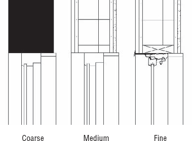
When we explored the notion of the view detail earlier, we mentioned the ability to show different levels of detail at coarse, medium, and fine settings. Combining this with detail components, you can embed details for typical conditions directly within the families themselves, so that you do not need to add more drafting elements to your views.
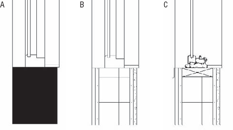
Figure 22.8 shows the same window family in coarse, medium, and fine views. All of the detail has been added to the family itself, and the detail is activated by switching between the levels of detail. Note that the fine detail level in this series shows the actual CAD detail from the manufacturer's website and is not modeled in detail in 3D. Modeling this level of detail within the Revit model would be a huge performance killer. Because the detail was created as part of the window family, this highly detailed information will be displayed each time any section or plan view is made that cuts through the window. This method enables you to have the level of detail always present in the drawings without having to give up performance or over-model the building.
Building this type of window family is not complicated, but it does require a bit of knowledge about how a family is created and assembled. For our purposes, we are going to assume that the window family has been created correctly and we are simply trying to apply more detail to the window itself so that it displays much more detailed information in fine view.
Since we have already created the sill condition, let's now focus on creating the head detail. Start by locating the family within the project using the Project Browser. Select it, right-click, and choose Edit Family from the context menu. The interface changes to the Family Editor environment. Open a section view (or if there is no section view, create a new one using the Section tool). The section view of the window family head will look like Figure 22.9.

In Chapter 21 we discussed how to insert default Revit detail components. For the blocking above the window head, we can load a detail component from the Revit default library. Here are the steps:
On the Home tab, click the Component button (or choose Place Component from the pull-down list). Next, click Load Family from the Place Component contextual ribbon. Then, once the browsing window opens, you will need to follow the path Detail Components | Div 06-Wood and Plastic | 06100-Rough Carpentry | 06110-Wood Framing and choose
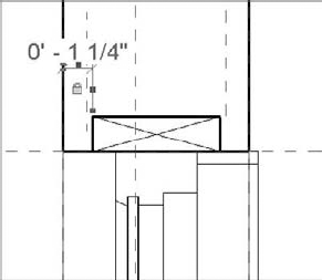
Nominal Cut Lumber-Section.rfa.Insert this component 1¼″ (3cm) from the exterior face of the wall. This ensures that it ends up in the right location relative to the wall it will be inserted into. If this window was going to be inserted into a variety of wall types, you could make the 1¼″ (3cm) dimension a parametric family parameter.
Once the component is inserted, lock it to the reference plane that is at the window head. This ensures that as window sizes are changed, the blocking moves as well.

Based on the window type, the blocking needs to always be set 1¼″ (3cm) from the front face of the wall, so you can add a constraint there as well. Add a dimension to the left edge of the blocking and the left edge of the wall, and lock it into place (Figure 22.10).
We want to create a new detail for the window head showing an added level of detail at the head condition. For this, we've downloaded the manufacturer's standard CAD detail and we want to incorporate it into our window. To begin, you need to create a new detail component using this CAD detail. From the Application Menu select New
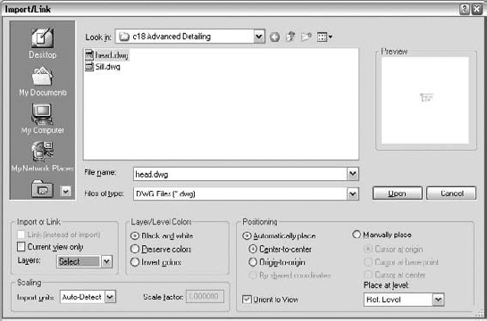
To import our CAD detail, follow the steps we discussed in the previous chapter. Choosing Import CAD from the Insert tab will bring up the dialog box where you can insert the CAD detail. This time, you'll want to choose slightly different options. Accept the defaults for all but the following:
Select the Black and White option in the Layer/Level Colors area
In the Import or Link area, change the Layers setting to Select (we want to pick the layers to import)
The dialog box will look like Figure 22.11. Click Open.
A dialog box similar to Figure 22.12 opens, asking you to choose the correct layers to import. Hatch is something we do not need, and typically, manufacturers are fairly good about keeping their layer management for CAD details consistent and easy to understand. We want to deselect any layers that reference hatch or any layers we know we will not need as part of our detail. Deselect the box and click OK.
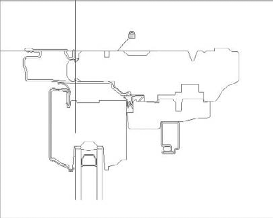
With the detail inserted, position it using the reference planes in the detail component. While you can reposition things within the Revit families fairly easily, these reference planes provide invisible snap references when loaded into a project—making placement and dimensioning easier and more specific. Because the top of the head and the face of the glass are key to this detail, use those to place the imported file, as shown in Figure 22.13.

With the detail exploded, you can now remove the glazing, which is only partially drawn. We have modeled glazing in the family itself, so including it in the detail as well is a bit redundant. Select the lines shown in Figure 22.14 and delete them. Instead of exploding the detail, another way to do these same steps is to go into the original CAD file and remove the lines and layers you don't need before inserting the detail into a Revit detail component.
The last thing you need to do before saving the model is change the line weights. Select all of the lines in the detail by creating a selection box around them, and while they are selected, choose Detail Items from the Type Selector. You could keep all of the lines the way they had been imported from CAD and change them to the appropriate line weight using Settings
Save the detail as
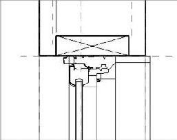
Head.rfain your project folder or library and import it into the window family using the Load into Project button on the Create tab.Back in the window family, place the detail component over the existing extruded window frame and lock it to the reference plane that defines the head opening (Figure 22.15).


With the detail components in place, you can now establish rules for when each of them will be visible when loaded into the model. You might not want to have your details shown in coarse or medium scales of 1:200 or 1:100, but you might wish to show them in 1:50 or 1:20 scale. In the next steps, visibility settings will be applied to some of the model elements and detail components that will link these items to the detail level setting. For this family, we need the detail component to be visible only in fine levels of detail and the 3D solid form window frame sweep to be hidden in fine levels of detail.

This dialog box is as simple as it looks, but it's quite powerful at the same time. By deselecting any of the options here, you limit the visibility of components to specific detail levels. For this example, clear the Coarse and Medium check boxes and click OK.

Now you will notice that a funny thing happens—or actually, doesn't happen. If you change the visibility of detail levels, the detail component still appears, although now it is drawn in a gray tone, as if it ignores the visibility settings you just made. You can quickly confirm that you deselected those view levels by checking the visibility settings again. Don't worry. You have done nothing wrong. In the Family Editor, for editing purposes, you will always see everything in each view detail level regardless of its setting. Only when you load the family in the project environment will you really understand if you have modified the visibility correctly.
The goal was to see the highly detailed representation of the window when switching to fine detail view. At the same time, you don't need to see the original 3D window frame because the linework of the frame will overlap with the linework of the newly inserted 2D detailing components. You need to turn off the visibility of the window frame from within the family when in fine detail view:
Select the 3D sweep created to represent the window frame and click the Visibility Settings button on the Modify Imports in Families tab. The dialog box that appears is the same as you saw previously when you selected the 2D detail component, but since this 3D element appears in more views, you now have more visibility options (Figure 22.17).
You still want to see the window frame in plan, reflected ceiling plan, and elevation, so leave those boxes checked for now and just uncheck the When Cut in Plan/RCP and Fine boxes, mirroring the settings for the detail component.

We will now add a trim. Use a masking region to cover the trim piece above the window frame on the exterior side of the glass. Use the boundary lines of the masking region to define the shape; it's not necessary to draw separate lines. Create it on the fly (Figure 22.18). While visually scanning through the manufacturer's product information, we selected a trim piece, but we don't have any Revit or CAD details for it. So, you have two options: make a new detail family and import it or build it on the spot.

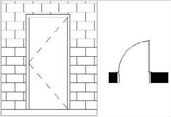
At this stage of the detailing process, you need to add sealant, flashing, and trim at the window head. For that you can use symbolic lines. Symbolic lines are 2D lines that are visible only in the view in which they were added. An example of the use of symbolic lines would be a representation of a door swing in elevation. The dashed lines that represent the hinge points are symbolic lines.
Using symbolic lines, add sealant to the detail, as shown in Figure 22.19.
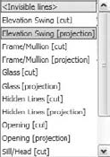
Before loading the detail into the project, you need to make sure the visibility of the symbolic lines and the masking region are correct. You cannot change the visibility of those elements simultaneously, so you'll need to select each one independently (choosing the masking region, then the symbolic lines) and set the visibility to show them only in fine detail views.

Doors are typically modeled in a closed position but shown as open and with a door swing direction in plan view. To get this dual representation, in the Family Editor turn off the visibility of the door panel (extruded solid form) in the plan view and draw the 90-degree open door panel and its swing using symbolic lines. Symbolic lines can be controlled using the same visibility settings available for detail components and the solid model elements in the family. You can use the same logic and draw the dashed lines that represent the door opening direction in elevations.
Save the family with a unique name before loading it. Once it is loaded, you can quickly cycle through the various view detail options and see the power of using visibility settings in the family, as shown in Figure 22.20.
Imagine that the door has already been modeled and you are adding the lines representing the swing. For that you add the symbolic lines in both plan and elevation to complete the element. When drawing new symbolic lines, use the Type Selector to define the subcategory of the lines.
There are many times in a project workflow when you want to leverage details already created in other projects and reuse them. So far we have covered how to do this using CAD files from other projects or from manufacturers' websites. This workflow is also possible using details created from other Revit projects. We will explain how to take an active project file and export key details to the library. We'll also discuss how to pull single details out of a Revit file and put them into your active project.
As you create more and more details in Revit, you will inevitably want to save some of them to your office's standard library so you can reuse them in other projects and save the work you've invested. Saving a view out of a project creates a separate RVT file that contains only that view. There are a couple of ways to do this, either of which will result in the same outcome. First, if you have a 3D model detail that you've embellished with 2D components and would like to save it for future projects, you can save it as a Revit file.
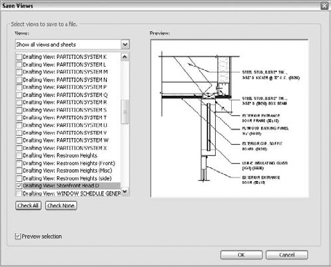
Right-click any view (or schedule) in the Project Browser and choose Save to New File. It might take Revit a minute to compile the view content, but you will be presented with a dialog box asking you for a file location to save the view (Figure 22.21). The default filename will be the same as the view name in the project.
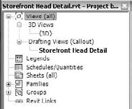
Once the view is exported, it functions like any other RVT file. Opening the view directly will allow you to edit and manipulate any of the elements you exported in the view. You will also see a streamlined version of the Project Browser (Figure 22.22) with only the related views present. These Revit files can be kept in a project library for later use.

The second way to export a view from Revit is from the Application Menu, using Save As
To import any of these files into a new project, switch to the Insert tab and from the Import Panel and choose Insert from File

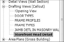
Notice that the view is described by both its location within the Project Browser (Drafting View) and its view name (Storefront Head Detail). Selecting this view and clicking OK merges the view into your current project. The view will appear in the location called out by the view name. In this case, you can find this view in the Project Browser under Drafting Views.
Another way to insert content into Revit is to use the 2D views from exported files. For example, elements of a detail you have in your library may need to be inserted into a view you are working on to augment that view. An excellent use case for this would be if you are creating a new detail and want to reference or use parts of one from another project that is similar but not exactly the same. An example of this might be a new detail of a window head in a concrete opening and you are reusing parts of a detail from a masonry opening. You may only want to use a selected portion of the new view in the current detail you are working on. To import the 2D content into your view, follow these steps:
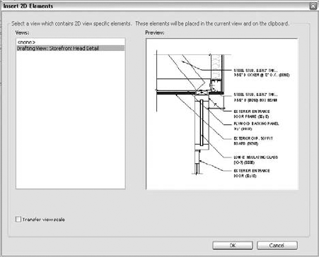
Open the view you want to import into, click the Insert tab and from the Import panel choose Insert 2D Elements from File. The resulting dialog box looks similar to the one for importing the full view but with some slight differences (Figure 22.25).
Unlike Insert Views, the Insert 2D Elements from File command allows you to choose only one view at a time to insert. There is also an option to transfer the view scale with the view elements. Checking this box reconfigures the receiving view to match the view that you have inserted.
Select the drafting view and click OK. This brings all of the 2D elements in the selected view into your active view. You can repeat this command multiple times in the same view window if you need to repeat the content.
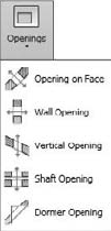
Revit offers a couple of ways to create an elevator shaft. One commonly used approach that we've seen discussed on the community forums is to create a door family that also contains all the elevator information (essentially, a combined door and elevator family in 3D). As a door family, it cuts a hole into a wall and gives proper representation of both the door and the elevator. This will give you your elevator, but then you need to perform a secondary task of editing the floor slab profiles to accommodate the shafts. Although this method will work, it can cause a problem with making sure the floor openings stay aligned between the floors. In our practice, we use a different method, which was used in creating the Foundation model. By using the Opening tool on the Modify tab, we can create a shaft opening.
This tool allows you to create one vertical shaft through multiple floors. This has a few benefits over the other method:
The openings in the floors will always be aligned
We can extend this shaft through as many or as few floors as desired
The constraints of the shaft can be locked to reflect the manufacturer's required size
Symbolic lines can be embedded in the opening to represent the elevator cab and can be drawn (or imported) to reflect the manufacturer's cab sizes and proportions
This last point is very valuable within our office. After creating the shaft, we can add the elevator cab plan directly from the manufacturer's CAD detail as symbolic lines.
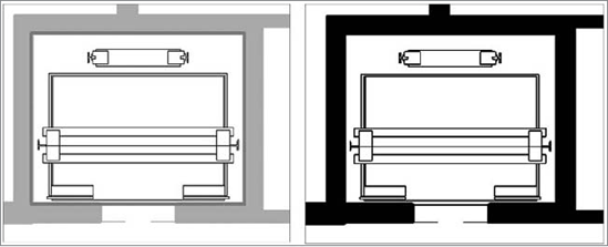
Now, any time we cut the shaft in plan, it will display the elevator cab using these symbolic lines. If our building is complex in form and we need to move our view range up or down, we will always maintain the elevator cab in the plans.
- Create 3D details.
3D axonometric details are a great way to demonstrate more complex assemblies and conditions in any document set. Knowing how to create them in Revit will expand the ways in which you can detail.
- Master It
Use a 3D axonometric detail to demonstrate constructability in a unique assembly condition.
- Add detail components to 3D families.
Adding detail components to 3D families can save time by embedding the linework of a detail within the family itself and making it instantly available throughout all the locations that family is placed.
- Master It
Create a detail by embedding it into a family so it can be expressed by simply modifying the detail level of a view.
- Reuse details from other Revit projects.
There are times when details are common between projects. Knowing how to use details from other Revit projects will cut down on your documentation time.
- Master It
Use details you created in your other Revit projects.