As design professionals, we are deeply rooted in the art of representation and expression. Our drawings are powerful communication devices and tools for personal expression. We manipulate color, contrast, light, and shadow to give a drawing life and dramatic poise. From the loose napkin sketch to the photorealistic rendering, we imbue our designs with a sense of purpose and intent. This intent is a driving force in architecture and critical to its progression. Without models and drawings that challenge the senses, where would we be today? Consider the drawings of Piranesi, Boullée, Wright, Woods, and Hadid. Each is distinct, thoughtful, evocative—at times utopian.
Consider your role in shaping the built environment. Think about how your drawings are interpreted, received, and understood. How do they shape the evolution of a design? How have digital tools changed the way you present and evaluate a design? Keep these questions in mind as we move through the next two chapters. Consider how the techniques can help you, and also think of how you might push some boundaries and extend your creativity using the tools in Revit
You've seen with Revit that many traditional documentation drawing types are generated with little effort. With a few clicks of the mouse, you can generate entire building sections and elevations. Likewise, a perspective view now takes only a few seconds to generate. Revit does a fairly good job of producing these drawings, but it can't fully replace the skill and decision-making process of an artist. Design intent and message still need to be considered by the designer. Because of this, Revit provides some tools to help you make your drawings more legible and expressive. If need be, you can also export a drawing as vector lines or as pixels and further refine it to meet your design requirements.
In this chapter, you'll learn to:
Use shadows for presentation purposes
Create presentation-quality plans and sections
Create elevation drawings that convey depth
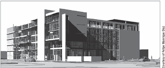
Shadows tend to be used for two purposes: analysis (Figure 15.1) and expression (Figure 15.2). For analysis, shadows are used to see how a building will be affected by its environment and real-world sun angles based on the location of the site. This analytic use is explored in depth in Chapter 18, "Evaluating Your Preliminary Design: Sustainability," and is covered here primarily to introduce the shadowing tools for presentation purposes. The expressive use of shadow, our focus in this discussion of presentation issues, conveys depth in drawings and gives them more character; it may or may not be tied to real-world sun positions. Revit provides a tool for each of these use cases, and this book will show you how to use both tools. The nice thing about shadows in Revit is that it's easy to enable them, and voilà!—shadows are there.
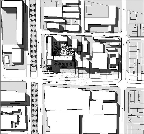
Figure 15.1. Analytical use of shadows in a site plan shows the effect of buildings on their environment.
Using shadows analytically allows you to see (and demonstrate) the effect of a building on its environment and, likewise, the effect of the environment on your building. Using real-world sun and building positions, you can evaluate the design impact on its surroundings. You need to know whether the building will have a negative impact and make sure building codes are satisfied. You'll also want to see the effect of the sun on the building itself so you can study light penetration and how other buildings will affect light and shadow. Figure 15.1 shows a site plan view with shadows turned on.
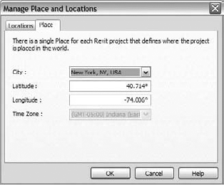
To get accurate sun shadows, you must establish where the building is on the planet, the building's orientation relative to north, and the date and time that you wish to analyze. For example, it's common practice all over the world to represent the extreme sun angles at both the summer and winter solstices. Both of these are provided in the default templates. These angles vary based on latitude and longitude. In Revit, every project has a location that is defined in the Manage Place and Locations dialog box that is accessible from the Manage tab, in the Project Location tab; this location has a direct influence on sun position. In the Place tab (shown in Figure 15.3), when you choose from a list of cities, the latitude and longitude are set for you automatically. If you don't find your city in the list, choose a nearby city, and then edit the latitude and longitude to match your location. If you're still not sure, you can use a tool like Google Earth to accurately locate your latitude and longitude.
You need to set your location only once per project; this will affect all sun angle calculations based on the selected location.
To turn on shadows and see the effect of date, time, and location, choose the Shadows On option from the view controls at the bottom of any view.

Shadows are enabled on a view-by-view basis. This means that for each view in which you wish to display the shadows, you need to activate them independently. The downside of this is that if you have activated the shadows in many views, there is no one global button to turn them all off; you might well have to do that throughout the course of the project, as shadows can slow down the performance of the project significantly. Alternatively, you can just close the views that have the shadows turned on.
To understand how shadows are being cast, click the Graphic Display Options button to open the dialog box shown in Figure 15.4, where all the shadow settings are defined. From this dialog box, you can access the Sun and Shadows Settings dialog box, play with the brightness and darkness of the sun and shadows, override silhouette edges, and enable gradient backgrounds.

Clicking the ellipsis button next to the Sun Position field opens a dialog box where you set the angle of the sun. For analytical views, choose meaningful times and dates. Revit ships with the presets shown in Figure 15.5.
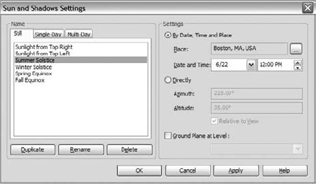
There are two methods for setting the sun angle: By Date, Time and Place; and Directly. Making any changes to them could cause serious problems later. For example, if you manually set Summer Solstice to an azimuth and altitude that aren't accurate, you can create misleading settings. If you need to create a unique setting, the best practice is to duplicate an existing setting and go from there, rather than editing the preset options. Or, if you really intend to change a preset setting permanently, go ahead and rename it with an appropriate and meaningful name.
To get different graphic results using the same geographical settings, try experimenting with the Sun and Shadows intensities in the Graphic Display Options dialog box by sliding the two sliders between the brightness and darkness extremes.

If you give the sun 100 percent intensity (Brighter), the model will appear brightly lit, and shadows appear more subdued. Figure 15.6 shows the different effects that can be achieved by adjusting the intensity values. Keep in mind that the sun and thus shadows affect only views set to Shading or Shading with Edges model graphic styles. In other words, for Hidden Line views, you can change only the darkness of the shadows but not the intensity of the sun.
To create several graphic versions of the same view, you must duplicate the view and apply different sun and shadow settings using the Advanced Model Graphics Settings dialog box.
When you use shadows expressively, the need for accurate lighting conditions is not as important as the need to define consistent angles so that your drawings express depth. Without shadows, a façade appears flat and difficult to interpret. By adding shadows and setting them to be Relative to View, you can create an image that discloses information about the depth in that flat image, allowing it to be much better understood. To do that, you establish a shadow angle that suits your needs and reuse the settings for multiple views. The default template includes two presets for this in the Sun and Shadows Settings dialog box: Sunlight from Top Right and Sunlight from Top Left (see Figure 15.7).
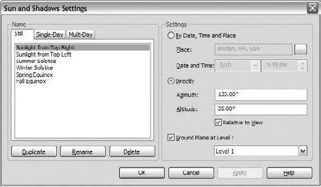
The combination of Azimuth and Altitude with these presets produces 45° shadows on an elevation.
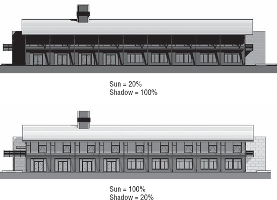
Using hidden line display and increasing the shadows to 80–90 percent produces nice, high-contrast elevations. As you can see in Figure 15.8, this is a great way to create visuals that will read from far away.

If you prefer to give an image a softer appearance, try using a shading view (shading without edges) and setting shadows to 30 percent and sun to 70 percent. You'll get a very even-colored, washed-out feel, as shown in Figure 15.9. Because the book is printed in black and white, you might not be able to appreciate the finesse in these, so make sure you try them out yourself!

As you'll discover when working in views with shadows enabled, the speed of panning and zooming in the model degrades when shadows are on. So, as you start to use shadows, keep this in mind: turning off shadows is always two clicks away. If you want to start panning and zooming around the view, turn off the shadows for a while. When you've finished zooming about, turn them back on. Remember that the settings are persistent, and turning off shadows is just a simple way to improve performance while working with your model. But don't worry—your work will be saved and you will not need to remake them again the next time you turn them on.
Colors, when associated with a legend, are an effective way to signify meaning. In the context of architectural drawing, the colors are often applied to convey how space is used or intended to be used. With Revit, you can use color to differentiate one room from another or to communicate ideas about usage, size, importance, and cost. By assigning parameter values to colors and patterns, you can quickly make views that show how a building is spatially organized (Figure 15.10). For example, you can create a department floor plan by assigning department values (names) to all your rooms and then apply a color fill scheme to the view that changes the color of rooms based on what department they're assigned to.

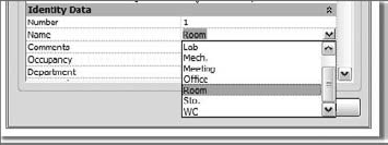
To make a color-coded plan, first duplicate an existing plan view and give it a unique name. Then add rooms (if they have not been added already). The reason for adding rooms is that the color-coding is based on the properties of room elements and will have no effect unless room elements exist in the project. You can also create new area plans and use area separation lines to divide space at a more macro scale. You can then assign values to each area that can then be colored with a color fill scheme. Once rooms and areas have been placed, you can access their Element properties.
All of the properties grouped under the Identity Data parameter group can be color-coded. Using project parameters, located in the Manage tab, you can also add custom parameters to the room and area categories.
From the View properties of a plan, area plan, or section view, you can assign a color fill scheme to the view. Clicking that parameter takes you to the Color Fill Schemes dialog box, where you set up and assign various schemes. Whatever is selected in that dialog box is applied to the view, and the rooms will become colored.
You can also create a color scheme using the Legend tool in the Home tab, in the Room & Area panel. The moment you place the legend, you will be prompted to select the space type (Rooms or Areas) and a color fill scheme.
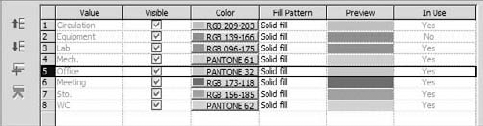
Color fill schemes are applied to views on a per-view basis (in other words, they appear only in the view where you created them) and are exposed as an Instance property of floor plan, area plan, and section views. To access and create color fill schemes, click to expand the Room & Area panel on the Home tab, and click Color Fill Schemes to open the dialog box in Figure 15.11 (you can get to the same dialog box from the View Properties dialog box). In the Edit Color Scheme dialog box, you'll see a list of schemes on the left and all the rules and colors for those schemes on the right. Each scheme colors one parameter and all its values. For each unique value, a unique color or hatch pattern is assigned. For example, if you choose to color by name, the table fills with all the room names in the project and assigns a color to each unique name. Clicking the button in the Color column allows you to choose your own colors. While Revit will create new colors for you automatically with each new value, you are free to change those to your own colors and can even save these into a template for use in other projects.


The color-scheme legend allows you to edit its Type properties to control the visibility of the title, swatch size, fonts, and color (Figure 15.12).
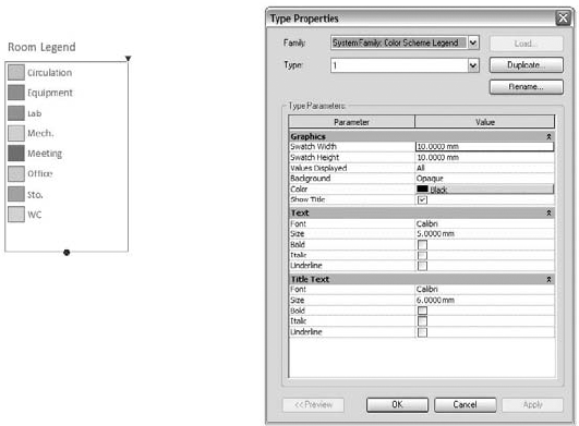
Note that the order of the values in the legend coincides with the order set up in the Edit Color Scheme dialog box. The default behavior lists each entry alphabetically, but you're free to change that by using the Move Up and Move Down buttons when a row is selected. Doing so simultaneously updates the color-scheme legend.
Another important graphical control of the legend is the Values Displayed parameter. This gives you the option to show only values in the legend that are also in the view (By View). In a project where the number of departments and room names can be large, and they aren't used in all floor plans, this is a great way to focus the legend on what is important to that view instead of listing all possible colors that might not be applied in that view and are thus irrelevant. Many designers do not want to display all the color swatches, but this is ultimately up to your own personal taste and what the drawings are intended to convey. Revit allows you to do both, so it's really up to you. Choosing the All option shows all values used in the project, whether used in the view or not.

If you've created a list of room names, departments, and a carefully chosen palette of colors that are likely to be reused in future projects, you can transfer the color scheme from one project to another or reuse it in your office template. This transfers all the values and colors, even if the project you're transferring to doesn't contain that value.
Imagine you have invested quite a bit of time setting up a color scheme in your current project, adding room names and departments and assigning them colors in the Color Fill Scheme dialog box. If you want to reuse the same values and colors in other projects so that you maintain your graphical language, use the following strategy:
Open the source project, and then open the project into which you want to transfer. You need to have two projects open to transfer from one to another. If you have only one project open, Revit will inform you that there are no open projects to transfer project standards from. Remember, the project in which you invoke the Transfer project standard is the one you wish to import the standards to.
Open the Manage tab, and then select Transfer Project Standards. Select Color Fill Schemes in the Select Items to Copy dialog box.

Values are transferred into the project. You can then access the list of values from the room's Element Properties dialog box.
This saves you from having to manually retype all these commonly used values, and the colors will be consistent from project to project.
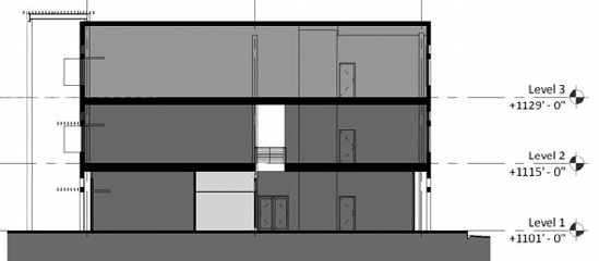
In architectural practice, section views as well as floor plans are often color-coded, showing the stacking of various functional zones (Figure 15.13). You can get automated coloring of the rooms in section view just as you can in plan view:
Open a section view.
From the context menu, under View Properties, open the Visibility/Graphics Overrides dialog box (type VG) and make sure the Rooms category in the view is checked as visible.
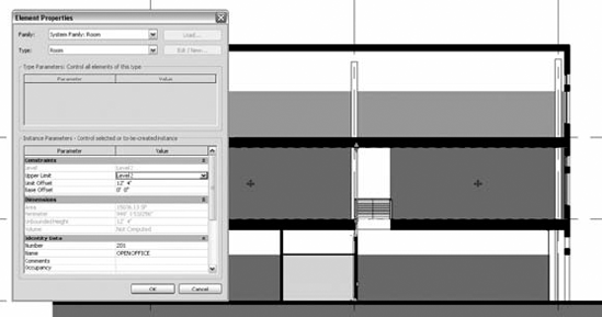
Open the View Properties dialog box and assign a Color Scheme setting to the view. Use Name as the parameter to color if you have not assigned any departments (departments are the default setting, which comes from the fact that the selection is alphabetical). You're likely to get an image where the rooms do not fill the entire space being cut by the section, similar to Figure 15.13. (Since this book is printed in black and white, use your imagination: purple is used on the first two floors and gray on the third.)
You can see that the rooms are not extending up to the next floor and roof. To fix this, select a room and drag the blue arrow controls at the top, or change the Limit Offset parameter from the element properties of the room.
To change how the color is drawn relative to the model geometry, you can set the color to be drawn in either the foreground or the background. This parameter is called Color Scheme Location and is a property of the view you are working in. Figure 15.14 shows the color in the background; the result is that you see walls and doors not colored by the color fill. Figure 15.15 shows the color in the foreground; now doors and walls appear filled in.

Not all plans and sections end up as drawings full of dimensions, tags, notes, and layers of construction information. Easy-to-read, graphically clean drawings are used all the time in marketing collateral, on project websites, in print magazines, for competition boards, and for client presentations. A great way to create presentation-quality plans and sections is to clear out most of the textual information and fill in walls, floor, and roofs with a solid fill when they're cut. This creates views that are easier to read and that convey solid and void effectively (Figure 15.16). With Revit, this kind of representation is a few clicks away, and the fill hatch is tied directly to the element. You don't need a paint-bucket tool or special hatch tool to get results.
There are two strategies for dealing with solid fill for elements that are cut: as a property of the element or as a property of the view. Each strategy has its own merits. Let's review the options.

Walls, floors, roofs, ceilings, and columns all have a Coarse Scale Fill type parameter. This allows you to define how the element will appear when cut in the view if the view detail level is set to Coarse.

The downside is that the property is stored with each type, so making all walls have the same hatch requires you to edit every wall type. The same goes for floors and roofs. And if you decide to change the color of the fill, you have to again edit every type.
Also, not all elements have this property. For example, in-place family walls, floors, and roofs don't have this parameter, so you'd have to go a separate route to get correct graphics if you chose to use this type of element.
The other way to think of this problem isn't as a property of the element but as a property of the view that can be reused in other views. Think of a view as a multidimensional lens through which you look at the model. Once you've set up the right lens, you can apply it to any number of views and get the right results using view templates. We recommend this direction for graphic overrides, as it makes for an easier way to deal with entire categories of elements. For example, most Revit categories can have their cut pattern overridden with a hatch or solid fill. If you go to the Visibility/Graphic Overrides dialog box and select the Walls, Floors, Roofs, and Columns categories (by holding Ctrl with each row selection), you can then click the Fill Override button and apply a solid fill hatch (Figure 15.17). This applies to elements in your active view but isn't stored with the element. These overrides are stored on a per-view basis and are distinct from the project-wide object styles.

This view setting is great—but what if you want to apply the same graphics to other views? Follow these steps:
Once you have the overrides set up, go to the Graphics panel on the View tab, and choose Create template from current view from the View Templates drop-down list.
Name the view Cut Overrides.
If you only want to store the cut pattern values and not affect scale or any other graphic settings when applying this view template, clear all other view properties except for the properties under the V/G Overrides Model (Figure 15.18).
Right-click the view name you want to apply the overrides to in the Project Browser, and choose Apply View Template. Choose the view template you just created.

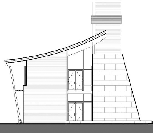
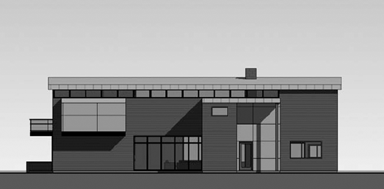
Revit applies the same line style to all edges based on the cut or projection settings in the Object Styles dialog box. This can lead to elevations that appear flat and lack depth. Strategies for dealing with this issue range from using a highly parametric approach to using lines and drafting right on the view. In Figure 15.19, the Linework tool and some graphic overrides were used to punch out the building elements in the foreground and halftone elements in the background.
The cursor changes to a pencil and highlights edges of the model as you move the mouse around the view. With each click, the override is applied to the edge. This override is associated with the element: if you move the element, the linework moves with it. The line style applies to the entire edge of an element by default, but this can be adjusted. For example, if you need to make the diagonal line of this wall with a thicker line style, you select the Linework tool, choose the Wide line style, and then select the edge of the wall. The line goes the entire length of the wall (Figure 15.20A). While still in the Linework command, click and drag the blue control dot to adjust the length of the linework override (Figures 15.20B-C). Note that if you have your view set to thin line display, you will not see the effects of using linework.
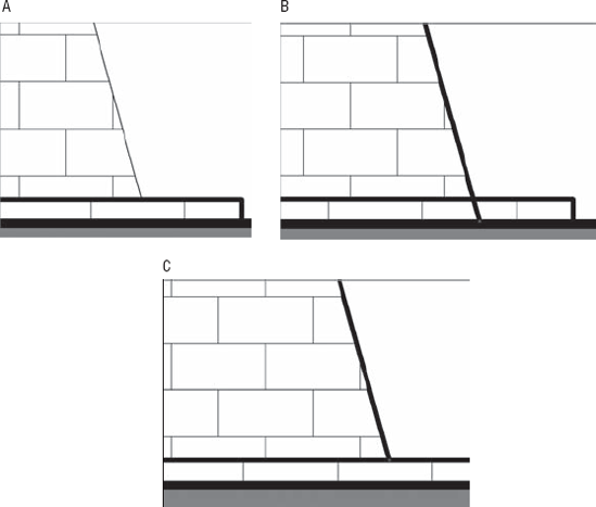
Figure 15.20. (A) Initial condition; (B) linework applied; (C) cleaning up the line by dragging the control at the end of the line.
To reedit the length of linework, you need to activate the tool and then again select the edge you're concerned with. The same blue controls appear, allowing you to adjust the length of the line.
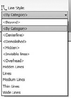
If you need to remove a linework override, the same principle applies: activate the Linework tool, choose <By Category> in the type selector, and then select edges in the model that you don't want overridden.
The other way to punch out the elevation is to use drafting lines and draw directly over the model in the view. This means you are not changing the appearance of a line in a view but instead are adding new lines on top of the model. With this method, you also choose a line style, and you can even use the Pick tool to get the same behavior you would with the Linework tool. The only difference is that the lines aren't automatically associated with the element you draw on. Depending on your workflow and where you are in the process, this may be the best way to create a final elevation drawing. A nice benefit to this method is that you have access to all Revit's familiar timesaving tools such as Trim, Align, and Multi-select.
Every material in Revit has a shading color and transparency. This is the color you see when the display mode is set to Shading or Shading with Edges. Be aware that the transparency is graphically visible only in 3D view. In elevations, a glass window will not appear as transparent; this helps keep drawings clear of unwanted visual noise. After all, who wants to see interior furniture showing through the glass of a hotel façade in an elevation? The color you select in the Materials dialog box will be an RGB or Pantone color (see Figure 15.21), but it often won't look like that color in shaded elevation views. That has confused many users, so here is the explanation: shaded views use a hidden fixed light source to light the scene, which causes the color to appear washed out or brighter in different views.
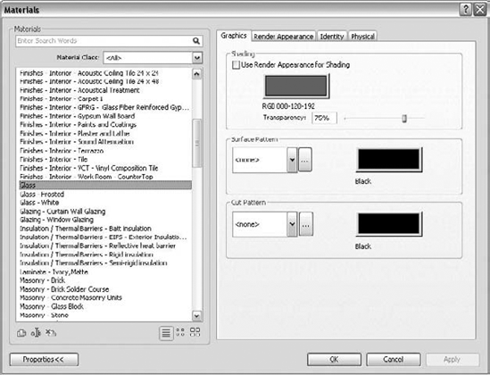
Figure 15.21. Every material has a shading color, transparency, and options for cut and surface patterns.
To overcome this limitation, you can control where the light comes from by using the Sun and Shadows Settings dialog box. You can also force the light to come from directly above the model so it doesn't affect any vertical surfaces. To do this, follow these steps:
Open the Sun and Shadows Settings dialog box, and duplicate the Sun from Top Right setting—give it a name like True Color Shading.
Change Azimuth to 0 and Altitude to 90 (see Figure 15.22).
Open an elevation view, and go to the Graphic Display Options dialog box from the view frame. Set the Sun Position to True Color Shading. Set Shadow Intensity to 0. Set Sun Intensity to 80.

Be sure to enable shadows in the view. The effect should be immediately obvious.
Using the standard Revit elevation views, transparent surfaces are always rendered as opaque surfaces. This generally produces the right quality and meets most expectations, but it can also seem limiting. Luckily, creating an elevation view with enabled transparency is easy using the 3D views and orienting them to display an elevation view. Here is how you can do that.
Open the default 3D view.
Right-click the View Cube and choose Orientate to View


The camera swings around so it's lined up with the elevation view, and transparent surfaces appear transparent.

You can import image files (click Image from the Import panel on the Insert tab) into a Revit view to create effects such as gradient fills, add a backdrop to the view, or add a photo-style entourage to a nonrendered view. By taking advantage of the draw-order options for images when placed in a view, you can position the image either in front of or behind the model. When you select an image, the Options bar gives you the ability to position the image in the foreground or background.
To add a gradient fill to the background of an elevation, follow these steps:
Import a gradient image file into an elevation view.
Select the image, and send it to the background using the Options bar.
Stretch the image to fit using the grip controls. You can unlock the proportional scaling using the Options bar (see Figure 15.23). If you tend to use the same image or entourage from project to project, keep in mind that you can keep a "library" of image elements in a drafting view.
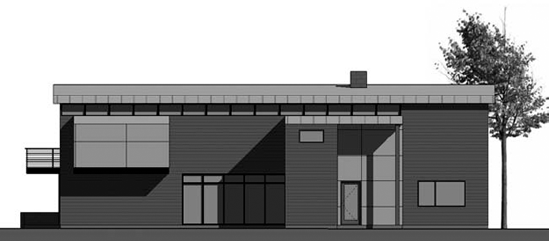
Another great technique is to use the transparency channel available in PNG-formatted images. By making a color transparent and pushing images to the foreground and background, you can add trees, people, and cars, and the image won't mask the model. In Figure 15.24, the tree image was imported into an elevation view and then copied and scaled. The copy on the right is set to Foreground, and the copy on the left is set to Background.
- Use shadows for presentation purposes.
Presenting your design to stakeholders is a critical part of your workflow and allows you to sell your ideas. Having tools that make this process easier without compromising your creativity is essential to being successful.
- Master It
You've been asked to show the effect of your building's shadow on its surrounding site during the winter solstice. How would you do this with Revit?
- Create presentation-quality plans and sections.
Creating clean, easy-to-read plan and section views using Revit is a huge timesaver.
- Master It
Your latest design is all the rage, and you've been asked to publish the plans and sections in a magazine. How do you make these?
- Create elevation drawings that convey depth.
Two-dimensional drawings can be hard for clients to read, which makes shadows a useful mechanism for illustrating recesses and projections.
- Master It
You need to give your elevation view more variation in line weight to convey depth beyond the default line styles established in the Object Styles dialog box. How do you do this?