In the previous chapters, we covered some advanced modeling techniques for making complex walls and curtain walls and for accommodating various specific conditions with roofs and floors. In this chapter, we explore some advanced stair and railing features that enable you to make some quite creative and smart designs. As you'll see, with a little refinement and creativity, you can create a wide range of railings and fences with a simple set of standard tools.
In this chapter, you'll learn to:
Work with railings and fences
Use balusters and rails to construct railings
Adjust additional settings
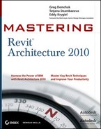
Railings and fences can range from very simple shapes to quite complex ones. A small selection of the possible variety of railings and fences can be found in the examples of the Revit help system (Figure 14.1). Railings and fences can be represented as simple walls that follow the sides of a stair or balcony, or the boundaries of your garden; you can also create glass frameless railings or complex combinations of balusters and posts in different materials (wood, metal, glass panels). Revit allows most combinations of railings to be built, but this does require a thorough understanding of the Railing tools, recognized as one of the more complicated tools in Revit.
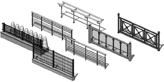
Figure 14.1. From the Revit help system, a variety of possible railings and fences that can be created with Revit.
In the following sections, we will cover some of the main principles used to create different types of railings in Revit.
When you need to create a railing in your model, Revit provides a customized tool to accomplish this. From the Circulation panel of the Home tab, choose Railing. You'll enter a Sketch mode where you have to first draw the path of your railing (Figure 14.2). You define the position and length of a railing by drawing a base line in Sketch mode. You can draw the base line of the railing wherever you please: in the center of the stair or on the side. The actual geometry of the railing is defined in the type properties, where you set up rail and baluster placement rules.


If you do not set a host prior to finishing drawing the railing, the railing will be placed below the stair, on the active floor or level. If you forget to do that and need to re-host the railing to a stair after sketching the railing, this is not a problem; you can re-host it later. To re-host, select the created railing, select the Edit Path tool available in the Edit panel of the Modify Railings tab, select Set Railing Host, and pick the stair as a host. Finish the sketch, and the railing will jump from the level to the stair.
Since a railing is based on a sketch line that defines its path, you can have your railing follow just about any path by drawing an appropriate line shape (Figure 14.3).
A railing element consists of the subelements shown in Figure 14.4: posts, rails, and balusters.

- Balusters
These can be any shape or form. A baluster repeats itself in a railing based on spacing rules. To place balusters, you first need to load existing baluster families into your project. These could be baluster families provided by Revit or your own custom content. To create your own designed baluster families, use one of three available family templates:
Baluster.rft, Baluster-Panel.rft, orBaluster Post.rft. Using the basic modeling tools explained in Chapter 6, "Modeling Principles in Revit I," you can make balusters such as those shown in Figure 14.5.- Posts
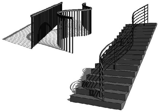
Posts can also have any shape, as shown in Figure 14.6. They are created using the
Baluster-Post.rfttemplate in the Family Editor.- Rails
Rails are horizontal elements that can either connect posts (should there be any) or represent handrails attached to a wall. The geometry of the rails is defined by profile families that you create in the Family Editor using the
Profile-Rail.rftfamily template. Figure 14.7 shows some examples of typical rail profiles.A rail can appear attached to a wall as a handrail, as shown in Figure 14.8. In this case, no posts are used and the wall-mount brackets are custom-designed balusters. The rail is following the stair and is given an appropriate offset from the wall.


The order and combination of subelements of the railing element can create unlimited variations of railings. In the type properties dialog box of the railing, under the Rail Structure and Baluster Placement parameters (Figure 14.9), you can define any combination of rails and balusters.

From the type properties of a railing, selecting Rail Structure
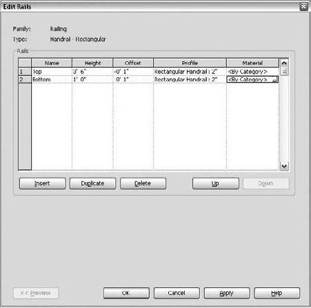
Figure 14.11 shows a railing with two rails: one set to 1′ (30cm) height and the upper one set at 3′−6″ (1m). Both of them use the profile Rectangular Handrail. The rails are placed with an offset to the mid-axis of the rail sketch line. (The balusters have no offset.) The 1″ (2.5cm) offset pushes the rail away from the sketch line, as you can see in the front elevation.
To define post and baluster patterns, click the Edit button for Baluster Placement in the type properties of the railing. You'll see the dialog box shown in Figure 14.12.
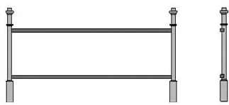
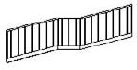
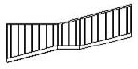
Depending on their position in the railing, posts can be placed at the Start, Corner, or End condition of the railing. You can choose to have different families for the three positions and thus select a different baluster-post family for each, or you can keep it simple and use the same family. You also don't have to have them at all—you can set the post placement to None for any of them (for example, you can have start and end but no corner). Figure 14.13 shows various possibilities for the placement of posts. On the railing at left, the start, corner, and end posts use the same post family. The railing at right was created with the corner post set to None and uses different post families for start and end posts.


The Corner Posts At dialog box allows you to define corner posts to be dependent on the angle of the railing or to only appear under certain conditions, or choose to not place them at all.
The option Angles Greater Than allows for inclusion of the element dependent on the set angle. This means that if the individual segments of sketch lines of a railing turn into angles greater than the parameter you set, a corner post will be placed (Figure 14.14). If the angles are less than the parameter, none will be placed.
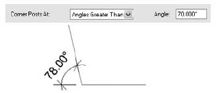
Figure 14.14. When the sketch lines of a railing meet at an angle greater than the angle defined for corner posts, a corner post will be placed.
As mentioned, railings can be hosted only on a slab, stair, ramp, or level. Thus, their placement is usually defined as an offset from the host. In the Edit Baluster Placement dialog box, you will find that you can also define the position of a rail as an offset from another rail that exists in the structure (Figure 14.15).

The Top parameter is where you can either select the host of the entire railing or choose from a list of existing rails in the railing as a top reference. The top offset can be a positive or negative value.
The Space parameter defines the distance of the post centerline to the railing viewed in a longitudinal direction, as shown in Figure 14.16. This value can be positive or negative.

The Main Pattern section of the Edit Baluster Placement dialog is where you define the pattern of the railing between the posts to generate a complex railing, as in Figure 14.17.

The options (Figure 14.18) are similar to those just discussed for the rails.

Note that all parameters that define position (such as Dist. [distance] from Previous or Offset) are calculated from the center reference planes of the baluster families.
The Dist. from Previous setting allows placement of balusters at a specific set distance from one another. To keep balusters from running into one another, you should know the actual dimensions of your different balusters prior to defining this parameter (Figure 14.19).

Figure 14.19. The baluster position is always measured to the mid-axis for all positioning parameters.
As you can imagine, the railing length will not always fit an even number of panels or balusters based on the pattern length. How do you deal with that?
Revit provides four different justifications for the pattern fit: Beginning, End, Center, and Spread Pattern to Fit. Their names explain the usage, but Figure 14.20 shows the different justifications and their implications for a design.
The justification you select obviously depends on your design, but you may also be using prefab standard railing patterns that come only in certain dimensions.
Revit allows you to set a specific number of balusters per tread on stairs.
If you want to control the number of balusters per tread, check the first option: Use Baluster per Tread on Stairs. This makes the next option active and you can then type in the number of balusters you want to have per tread. You can also change the baluster family by clicking the Baluster Family option, which displays a list of all loaded baluster families available in the project.

Figure 14.20. Using different pattern options for seven defined panels results in different distribution of the panel along the railing length.
The top and middle images in Figure 14.21 show railings for spiral stairs created with two different settings: (A) two balusters per tread, and (B) one baluster per tread setting. When the bottom image (C) was created, the Use Baluster per Tread on Stairs option was not activated, so the railing follows the main pattern.
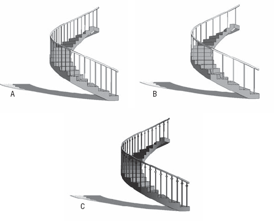
Figure 14.21. Spiral stairs with different settings: (A) two balusters per tread; (B) one baluster per tread; (C) Use Baluster per Tread on Stairs option not activated.
As you can see, the moment you use the Use Baluster per Tread on Stairs option, the Baluster Family selection overrides the one set in the Main Pattern section.
Landings can be difficult to work with when designing railings. Revit has a set of additional tools to control landings located in its Type parameters (Figure 14.22).
By default, each railing in Revit follows the stair flight and the landing and creates the most logical solution. Often, however, the height of the railing on a landing is not calculated according to your design intent. With the Use Landing Height Adjustment parameter, you can change the railing at the landing to a specific height.

Landings can also generate unresolved situations where segments of the railing meet. By default, the joins at the angles are unresolved and the segments are not connected. You can fix that by adding vertical or horizontal segments and refine it further by setting the rail connections to Trim or Weld (see Figure 14.23). All these settings are also part of the type properties for the railing.

Figure 14.23. Angled joins: (A) no connector; (B) add vertical or horizontal segments; (C) with rail parameter set to Trim/Weld.
The Tangent Joins tool does a similar job but affects connections of different segments of the railing that are on a continuous tangent. The options are located in the type properties of a rail.

The effects can be seen in Figure 14.24.
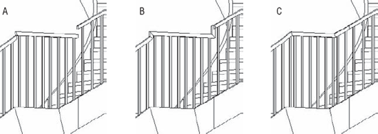
Figure 14.24. Mid-landing railing segments cleanup: (A) No Connector; (B) Add Vertical Segments; (C) Extend Rails to Meet.
Finally, there are a few more adjustment tools needed to refine the railing and bring it closer to your design goals. These last tools are available in Sketch mode of the Railing tool only.
Use the Edit Rail Joins tool to clean up segment joints while in the railing sketch. Once you're in a Sketch mode, this option appears in the Tools panel of the Modify Railings tab.

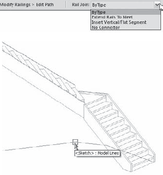
In Sketch mode, after you select one of the railing sketch lines, the Options bar tools shown in Figure 14.26 appear. These tools let you manipulate the sketch lines in order to adjust the slope of the railing or correct the height connection.

The Slope tool offers you three possibilities:
- By Host
This option follows the slope of the host, which is what you would need in the majority of cases.
- Flat
This option keeps the railing flat, regardless of the slope of the host.

- Sloped
This option defines a custom slope for your railing that ensures uninterrupted connection between adjacent segments.
Similar to what we have shown about the height adjustment on the landing, there is an additional adjustment of the height of a railing that is useful for controlling the extension of a railing (Figure 14.27).
This is also available when in Sketch mode only and offers two options:
- By Type
The railing height for the selected segment depends on the properties of the railing type.
- Custom
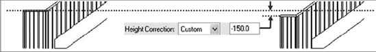
The railing height for the selected segment can be forced to a different custom value. Figure 14.28 demonstrates both situations.
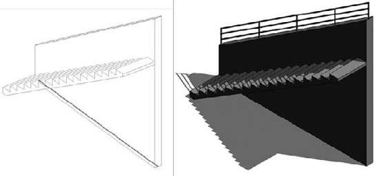
Adding a rail to stairs is easy, but adding a rail on top of a wall is more difficult the way Revit elements are set up today. Shown here is a railing design consisting of a base wall and a railing element on top of it. This is a common type of railing in institutional buildings or outdoor stairs, so let's see how it is made.

The challenge we face is that a wall is not considered a host for a railing element in Revit, so we have to find a workaround for how to place a railing that will follow the stair angle and is based on the wall.
Start by creating a stair without any railings (or if you already created a stair with default railings, delete the railings later) and create a wall next to the stair with an edited elevation profile, as shown in the previous graphic.
Then create a very thin floor on top of the wall that will play the role of a host for the railing (a floor is a valid host for railings):
Create a floor type that is very thin.
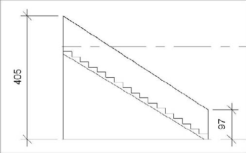
Switch to elevation view. Using the Dimension tool, measure or dimension the height of the top of the wall at the beginning and end of the stair. You will need these values when you slope the floor to match the stair.
Define the floor shape by switching to plan view and drawing a floor. Use the Pick method and select the four lines representing the top of the wall.
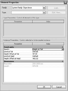
While still in floor Sketch mode, click the Slope Arrow tool and set the properties as shown:
For Specify, choose Height at Tail
For Height Offset at Tail, set the value of the lower height of the wall to 3′−0″ (97cm)
For Height Offset at Head, set the higher value of 12′−0″ (405cm)
Draw the slope arrow in the middle of the floor starting at the beginning of the stair and finishing toward the end of the stair. By doing this, you have added a slope to the floor that matches the slope of the wall.

Select the Railing tool from the Circulation panel on the Home tab, then click on the Set Railing Host button on the Tools panel of the Create Railing Path tab, and select the floor, and draw the railing in the middle of the floor.
This workaround can be quite practical when dealing with railings in big auditoriums. Auditoriums are rarely done using huge stairs; rather, they tend to feature stairs divided into many floors. As a railing can only have one host, it isn't possible to host the railing on many floors at the same time. Using this workaround, however, you will be able to create a railing that runs through many auditorium levels and is still hosted.
- Work with railings and fences.
Railings are a bread-and-butter architectural element whose design can be streamlined with Revit.
- Master It
You've found some nice-looking railing panels and balusters while scouring the Web for interesting rail designs. How do you go about building the railing in Revit?
- Use balusters and rails to construct railings.
A railing is a complex set of subelements that Revit lets you organize and control with rules and settings.
- Master It
You want to make a railing where the balusters are glass panels with fixed width. You wish to add a railing that contains the maximum number of those panels and you wish them to be spread symmetrically. How do you do that?
- Adjust additional settings.
Stair railing details are particularly difficult to design and plan at landings. Revit helps you fine-tune the details using additional settings.
- Master It
After designing the stair railing, you notice that there is a gap between the rails following the stair flight and the horizontal rail on the landing. What options do you have to resolve this situation?