
In the previous chapters we covered basic modeling techniques for constructing a simple building. We skipped over many additional features to give you a handle on essential workflow, the user interface, and making modifications to the model. In this chapter we cover more advanced features that are available any time you're modeling in Revit. As you'll see, with a little refinement and creativity, you can create a wide range of building components using the standard tools.
In this chapter, you'll learn to:
In real life, roofs can come in many shapes, sizes, and degrees of complexity. They can be as simple as a single-pitch shed roof, or they can involve complex sine curves or intersecting vaults. Once you understand Revit's primary concepts, logic, and tools, you will be able to design just about any roof shape.
In general, roofs in Revit can be constructed in four different ways:
- Roof by footprint
Use this method to create any standard roof that more or less follows the shape of the building footprint and is a simple combination of roof pitches.
- Roof by extrusion
This method is best applied for roof shapes that are geometrically generated by extrusion of a profile, such as sawtooth roofs, barrel vaults, and waveform roofs.
- In-place roof
This technique is used to accommodate roof shapes that cannot be achieved with either the footprint or extrusion methods. They are either done by using the general modeling techniques and applying a roof category to that geometry, or by using an underlying mass form.
- Roof by face
In this technique, you select faces of massing forms to create standard thickness roofs. You can create those underlying massing forms within Revit, or import geometry created in other modeling applications into a mass family and use it as an underlay to create the roof by face. This technique is discussed in more detail in Chapter 8, "Concept Massing Study: Early Design Phase."
The following sections provide a close look at these approaches and review their application to real-world scenarios.
Use the roof by footprint method to create any standard roof that more or less follows the shape of the footprint of the building and is a simple combination of roof pitches (Figure 13.1).

These roofs are based on a sketched shape that you define in plan view at the soffit level and that can be edited at any time during the development of a project from plan and axonometric 3D views. The shape can be drawn as a simple loop of lines using the Line tool, or can be created using the Pick Walls method, which also should result in a clean closed loop of lines. The latter means that the exterior walls are used to define the shape of the roof.
The best way to conceptualize the roof by footprint method is to understand that the sketched shape defining the main shape of the roof is just a simple, closed loop of lines—nothing more than that, regardless of whether it's drawn or picked.
The Pick Walls method provides an intelligent selection method, so if you select walls as references to generate the sketch lines, with or without an offset to the walls, the lines will maintain a smart relationship with the walls. The Pick Walls method is the suggested approach for creating roofs by footprint. By selecting the walls to generate the sketch for the roof, you are creating an exclusive relationship between the walls and the roof so that if the design of your building later changes (wall position, level height, wall height, etc.), the roof will follow that change and adjust to the new wall position without any intervention from you (Figure 13.2). Like any change in Revit, this happens everywhere in all views, and thus not only the model but also its entire documentation and related quantities will be updated. This will not automatically occur if you just drew the roof lines and did not explicitly create a relationship between them and the underlying walls.
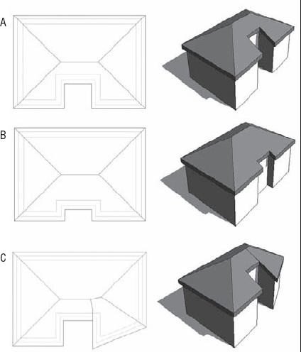
Figure 13.2. Examples of using the Pick method: (A) original roof; (B) entrance wall position has changed and roof has been updated automatically; (C) angle of wall to right of the entrance has changed and roof has changed to a new shape.
To guide you through the creation of roof by footprint and explain some of the main principles and tools, here is a brief exercise demonstrating the steps:
In a new project, open a Level 2 plan view and create a building footprint similar to Figure 13.3.
From the Draw panel in the Create Roof Footprint tab, select the Pick Walls tool (this should be the default).
When you've chosen to create a roof by footprint, the Options bar makes the tools shown here available.

To define whether you want a sloped or flat roof, use the Defines Slope check box in the Options bar. The Overhang parameter allows you to define the value of the roof overhang beyond the wall. When the Extend into Wall (to Core) option is checked, the overhang is measured from the wall core. If the option is deselected, the overhang is measured from the exterior face of the wall.
After defining these settings, place your cursor over one of the walls (don't click). Press the Tab key. This will result in both automatic selection of all walls and automatic indication of the roof overhang around those walls. Once you see the entire roof overhang indicated around all walls, click with the mouse over the wall. The dashed lines indicating the overhang will turn into solid lines, confirming that the roof sketch is created. The lines will be offset from the walls by the value of the overhang that you defined in the Options bar. Your display should look like Figure 13.4.
Click the Finish Roof button at the top right of the ribbon menu.


If at any time the shape of the roof doesn't meet your expectations, you can select the roof and select Edit Footprint from the Edit panel in the Modify Roofs tab to return to sketch mode, where you can edit lines or sketch lines or the slope.
To change the slope definition or angle of individual portions of the roof, select the roof, and then from the Edit panel, click Edit Footprint. This brings you back to Sketch mode; select the sketch line of the roof portion for which you wish to change the slope and either toggle (check) the Defines Slope button in the Options bar to remove or add a slope, or click the slope value that is displayed when you select the sketch line to change the slope angle. If you mistakenly made all roof sides with slope but wanted to make a flat roof, you can Tab-select all sketch lines that form the roof shape and clear the Defines Slope box in the Options bar.
Roof slope can be measured in different ways: it can be set as an angle or percentage rise. You can find all slope measuring options on the Manage tab by selecting the Project Units in the Project Settings panel and then selecting Slope (see Figure 13.5). If the current slope value is not expressed in the units you want to use (such as percentage when you want it to display an angle), you'll need to change the slope units in the Format dialog box. (You will not be able to do this while editing the roof slope.) Setting it here means specifying the way you measure slopes for the entire project.

Here are some of the important instance properties you should be aware of and know how to set properly. All are found in the dialog box shown in Figure 13.6:
- Base Level
As in other Revit elements, this is the level at which the roof is placed. The roof moves with this level if the level changes height.
- Room Bounding
When this is checked, the roof geometry has an effect on calculating room area and volume.
- Related to Mass
This property is active only if a roof has been created with the roof by face method (Conceptual Mass tools).
- Base Offset from Level
This option lowers or elevates the base of the roof relative to the base level.
- Cutoff Level
Many roof shapes require a combination of several roofs on top of each other. To do this, you need to cut off the top of a lower roof to accommodate the creation of the next roof in the sequence. Figure 13.7—in which the cutoff level is applied to the main roof and a secondary roof is built on top of the main roof using the cutoff level as a base—is an excellent example of this technique.
- Cutoff Offset
When the Cutoff tool is applied, the Cutoff Offset value also becomes active and allows you to set the cutoff distance from the level indicated in the Cutoff Level parameter.
- Rafter Cut
This defines the eave shape. You can select from Plumb Cut, Two Plumb Cut, or Two Plumb Square. When Two Plumb Square is selected, the Fascia Depth parameter is activated and you can set the value for the depth.
- Rafter or Truss
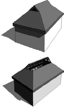
With Rafter, the offset of the base is measured from the inside of the wall. If you choose Truss, the plate offset from the base is measured from the outside of the wall. Figure 13.8 is a typical example of a roof by rafter cut.


The roof by extrusion method is best applied to roof shapes that are generated by extrusion of a profile, such as sawtooth roofs, barrel vaults, and waveform roofs. Like the roof by footprint method, it is based on a sketch; however, the sketch that defines the shape of the roof is drawn in elevation or section view (not in plan view) and is then extruded along the plan of the building (see Figure 13.9).
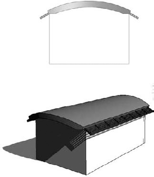
Figure 13.9. A barrel-shaped roof extended with sunshades. The main roof is an extruded arch sketch.
The Roof by Extrusion tool offers additional settings in the Options bar when selected.

Here's a brief explanation of how the tool works. First you create your roof by extrusion by defining a profile in elevation that is then extruded above the building. The extrusion follows a straight path, which probably is not the same as the building footprint (unless your building footprint is also a straight rectangle in shape). If the shape of the building is nonrectangular in footprint or the shape of the roof you want to create is not to be rectangular, this tool will let you carve geometry from the roof to match the footprint of the building or get any plan shape you need using a plan sketch.
You will recall that with sketch-based design, any closed loop of lines creates a positive shape, every next loop inside it is negative, the next one inside that negative one is positive, and so on. In Figure 13.10, a roof by extrusion was drawn at an angle to the underlying walls, but the final state should not extend beyond those walls. To clip the roof to meet the walls, the Vertical Opening tool was used to draw, in plan view of the roof, a negative shape that will remove the portions of the roof that extend beyond the walls.

The roof-in-place technique accommodates roof shapes that cannot be achieved with either of the previously mentioned methods. It is the usual way to model historic roof shapes or challenging roof geometries such as domes and onion-domed roofs (see Figure 13.11).

Here's the concept: you create a geometry using the Component tool found in the Home tab and select Model In-Place; then you can assign a roof category to it, and go wild with your creativity.
To start an in-place roof family, click the Component tool in Build panel of the Home tab. Select Roofs from the Family Category list (Figure 13.12), and click OK. This list allows Revit to assign a specific category (Roof in this case) to your in-place model and thus later schedule the new element as a roof.
You can create any roof shape using Solids and Voids and the modeling techniques of Extrusion, Blend, Revolve, Sweep, Swept Blend, or any combination of them (see Figure 13.13). There is a lot more information about some advanced shape-editing techniques later in this chapter, in the section "Working with Advanced Roofs and Floor Shape Editing."


You saw earlier that a curtain wall is just another wall type made out of panels and mullions organized in a grid system. Similarly, sloped glazing is just another type of roof that has glass as material and mullions for divisions. Using sloped glazing, you can make roof lights and shed lights, and use them to design simple framing structures.
To create sloped glazing, make a simple pitched roof, select it, and use the Type selector available upon selection of the Change Element Type tool to change the type to Sloped Glazing. Once you have done that, switch to a 3D view and use the Curtain Grid tool to start applying horizontal or vertical grids that define the panel sizes; then you can apply mullions. Figure 13.14 demonstrates the process of converting a standard roof into sloped glazing.
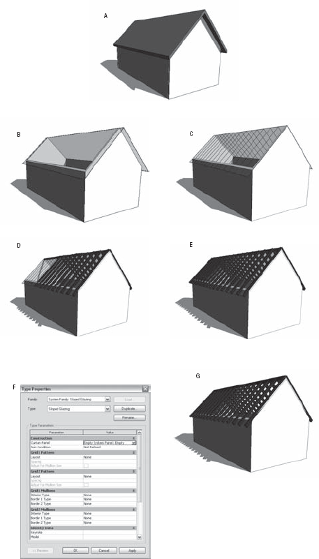
Figure 13.14. (A) Standard roof. (B) Convert a standard roof into sloped glazing. (C) Divide with curtain grid. (D) Add mullions to the grid. (E) Finish applying all mullions to the grid. (F) Change curtain panel from glass to empty. (G) Finished rafters.
Suppose we are planning a factory whose roof needs to be a ridge skylight on a pitch.
Here's how to make this roof:
In Level 1, draw the floor plan of the building. For the sake of simplicity, we will assume that the floor plan is a rectangle.
Switch to any elevation view and define two new levels in the drawing: Level 2 at 12′ (4m), and Level 3 at 18′ (6m).
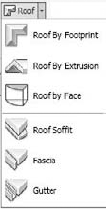
Switch to Level 2 and from the Home tab on the Build panel, expand the Roof tool.
Select Roof by Footprint.

Click the Pick Walls tool from the Draw panel.
In the Options bar, define an Overhang setting of 1′6″ (50cm), and check the Defines Slope option.
Click Finish Roof (at the far right of the Create Roof Footprint tab).
Once you complete these steps, this is how the resulting roof should look:

We now need to cut the top of this roof at Level 3.
Select the roof and, in its instance properties, select Level 3 under Cutoff Level and −1′8″ (−57cm) for Cutoff Offset (the roof thickness value); then click Finish Roof. The result looks like this:

Next, we'll create the second roof and use the opening in the first roof as a reference for the sketch lines defining the new roof:
Switch to Level 3 and select the Roof by Footprint tool. Instead of selecting the Pick Walls option from the Draw panel, select the Pick Lines tool, right next to it.

You will notice a Lock option in the Options bar. When checked, this option will lock the newly generated lines to the lines of the lower roof that you use as a reference. Check the Lock option.
Now select the four edges of the opening of the first roof: this results in the creation of four new rooflines for the upper roof that have a relationship with the lower roof sketch lines indicated by the four closed padlocks.
Click Finish Roof.

You just created the upper roof but also a relationship between the two roofs. That way, if you later change the cutoff level or the geometry, the second roof will change to match the new cutoff level.
Select the newly created roof, and select the Change Element Type tool to open the Type Selector. From there, pick Sloped Glazing to get the following configuration:

If the slope of the upper roof isn't what you desire, you can change it at any time. Select the roof, click Edit Footprint in the Edit panel of the Modify Roofs tab, click each of the sketch lines, and type in a new value over the slope value displayed. In this example, we have set 9″ for the upper roof (the skylight).
Divide the sloped glazing into segments and apply mullions. For that, use the Curtain Grid tool located in the Build panel of the Home tab and start dividing the glazing.
Add mullions by selecting the Mullion tool from the same Build panel and picking the gridlines on the glazing. The final outcome should be similar to this:

Another way to slope a roof is by manually adding slope arrows to a sketch of flat roof slabs. This can be useful for unusual shapes, especially if the roof edges are not straight.
Once you've drawn the slope arrow, you can select it, and click on the Properties button in the Draw panel to open the Instance properties dialog box and set any of the parameters shown in Figure 13.16. The most critical parameter to check is Height Offset at Head. This defines the height of the roof slab from the base to the top of its slope.

To create a shed roof, you can draw a roof without any slope-defining sides and then apply a slope arrow that defines the exact sloping (see Figures 13.17 and 13.18).

The following section demonstrates a series of typical roof conditions and the appropriate strategy to use in Revit to create these roofs. For any roof, there can be many ways to solve it geometrically. You can use this section as a guide and to shore up your skills with the roof tools and methods described previously in this chapter.
Each roof in the typology is represented with the roof plan view, sketch plan, and 3D view of the roof.
We created this flat roof using Roof by Footprint and the Pick Walls tool; we also unchecked Defines Slope on the Options bar.

We also created this roof using Roof by Footprint and the Pick Walls tool. But in this example we checked Defines Slope for the shorter sides of the roof, and the slope angles are not identical.

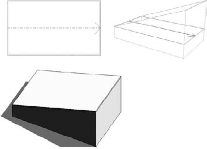
We created this Roof by Footprint by using the Pick Walls tool and checked Defines Slope for only one of the short sides of the roof.

Note that you could also make this same roof by adding a Slope arrow to a flat roof:
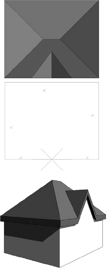
We created this Roof by Footprint by using the Pick Walls tool, and Defines Slope was checked for all sides of the roof.

We created this Roof by Footprint by using the Pick Walls tool. Defines Slope was checked for all sides of the roof except the three walls that recess toward the inside.
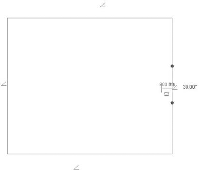
We created this Roof by Footprint by using the Pick Walls tool and checking Defines Slope for all sides of the roof but not for the one that recesses toward the interior of the building.

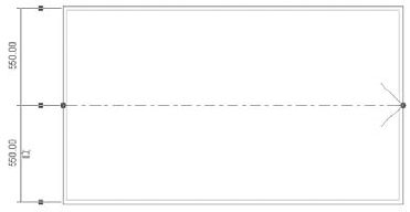
This Roof by Footprint was created over a rectangular floor plan using the Pick Walls tool. We then edited its sketch and included additional sketch lines to shape the extension. We checked Defines Slope only for the sides indicated in the sketch.

We created this Roof by Footprint by using the Pick Walls tool with Defines Slope checked for all sides.

Notice that we split the sketch lines of the shorter sides in thirds and checked Defines Slope only for the middle portion of the line, as shown here
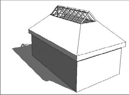
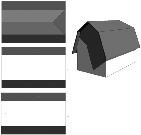
We created this Roof by Footprint by using the Pick Walls tool. We checked Defines Slope for the two long sides of the roof only. We cut the roof off at a certain height (cutoff level), and created a second roof using as a sketch the cutoff shape of the first roof. For the second roof, we checked the Defines Slope option for its two longer sides.
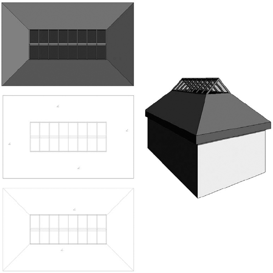
We created this Roof by Footprint by using the Pick Walls tool and checking Defines Slope for all sides of the roof. We cut the roof off at a certain height (cutoff level), and created a second roof using as a sketch the cutoff shape of the first roof. We set the Type value of the second roof to Sloped Glazing. For the second roof we also checked Defines Slope for all sides of the roof, but the slope of the second roof is slightly steeper than that of the first roof. We applied curtain grid and mullions to the sloped glazing. (See "Real World Scenario: Creating a Ridge Skylight Roof" earlier in this chapter for a full step-by-step procedure for this example.)
We created this Roof by Footprint by using the Pick Walls tool and checking Defines Slope for all sides of the roof. We cut the roof off at a certain height (cutoff level), and we created a second roof using as a sketch the cutoff shape of the first roof. We checked Defines Slope for all sides of the second roof; the slope of the second roof is slightly steeper than the slope of the first roof.

We created this Roof by Footprint by using the Pick Walls tool and checking Defines Slope for all sides of the roof. We split the sketch line on the south of the building into four segments to allow for the dormer creation. We added sloped arrows facing each other and meeting in one point to the middle two segments of the split sketch line.
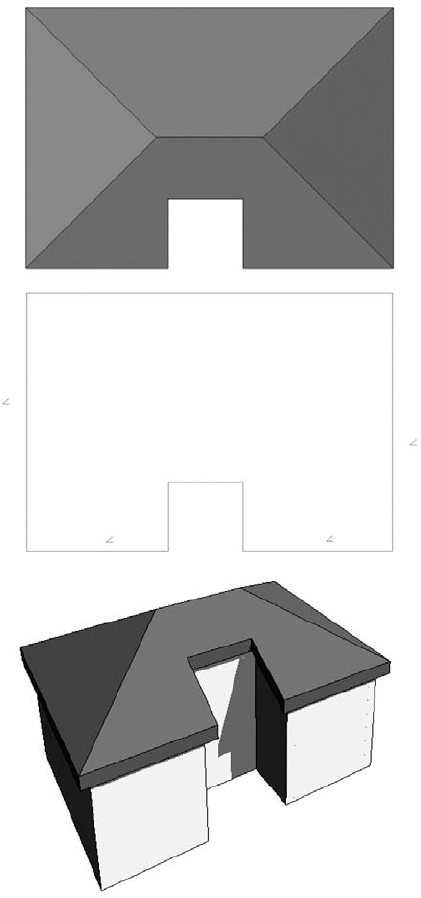
We created this Roof by Footprint by using the Pick Walls tool and checking Defines Slope for all sides of the roof. The two dormers are also separate roofs created by the footprint of the walls defining the sides of the dormer. We then joined the roofs. The opening in the roof slab is made up of two simple closed loops of lines (this can be done directly in Sketch mode or later, using the Openings tool from the Modify tab).

We created this Roof by Footprint by using the Line tool from the Draw panel in the shape indicated in the sketch. Defines Slope is checked for all four corners (see the blowups of the corner and middle roof edge).

We created this Roof by Footprint by using the Pick Walls tool with Defines Slope checked for all sides of the roof. We created the dormer roof as a roof by extrusion by using the wall face as a work plane, and then joined with the other roof in the sketch (you could also use the Openings tool later).

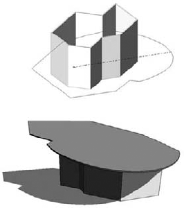
We created this in-place roof by using the Component tool and selecting Model In-Place from the Build panel of the Home tab, with Roof as the assigned category. A simple closed loop of sketched line is revolving around an axis.
This roof can also be created as a footprint roof that is sketched as a circle while Revit is in sketch mode. Make sure that the number of full segments is set to 0. Adding three or more segments created even faceting.
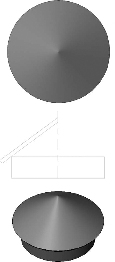
This dome was also created as an in-place roof using the Revolve modeling technique. To replicate it, you will first need to draw a reference line in plan view that crosses the center of the circle describing the exterior walls, and then, in section view, draw the revolving shape as well as the axis of rotation.

We created this example with the Roof by Extrusion method. A simple line in arc shape defines the main shape of the roof extruded over the building footprint. In this example we included an additional roof by extrusion and converted it into sloped glazing. The edges of the roof have been rounded using the Vertical Opening tool. The sloped glazing curtain panel type is set to Empty Glazing, which allows the mullion structure to create a sunshade.

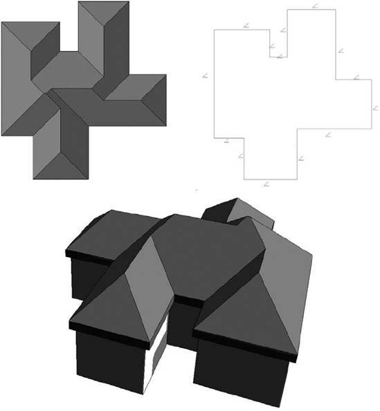
We created this Roof by Footprint by using the Pick Walls tool with Defines Slope checked for all sides of the roof. Regardless of how complicated the underlying footprint, Revit correctly calculates the ridges as long as the eaves are aligned.
Roofs with dormers generally cause grief for architects, so we'll guide you through the creation of one.
Create the base of a building, set up three levels, and create a Roof by Footprint with Defines Slope checked for all sides.
Approximately in the position indicated in the following graphic, on Level 2 create the four walls of a dormer using the Wall tool. Set their height to such a value that they extend above the roof. (For easier verification, create a cross section through the dormer to check the height of the dormer walls, and if necessary, modify their height in the element properties so that they extend above the roof.)
Using the Roof by Footprint tool, create a pitched roof on top of the dormer walls.
If you switch to a side elevation view, you will notice that the dormer roof probably does not extend to meet the main roof. Therefore, you will need to use the Join/Unjoin Roof tool, located on the Modify tab in the Edit Geometry panel, to join the main roof and the dormer. Select the Join/Unjoin Roof tool, select the main roof as the target, and then select the edge of the dormer roof to extend.

From the Edit Geometry panel on the Modify tab, expand the Openings tools and select Dormer Opening. Now pick first the main roof, then the dormer roof, and then the sides of the walls that define the dormer. Select the inside faces of the walls. Unlike with most sketches, in this case you will not need to provide a closed loop of lines. Finish the dormer opening.

Go back to the section view you previously created and edit the elevation profile of the walls to make sure they don't extend below or above the roofs. Note that you should not use the Top/Base Attach tool; instead use the Edit Profile tool available in the Edit panel on the Modify Walls tab to edit its elevation profile. Then manually change the base sketch line of the walls to get the triangular elevation profile as shown here:

Your dormer opening is now correct and you will see that it has cut the roof in two directions, as a true dormer needs to.


As a final touch, you can convert the front wall of the dormer to a storefront wall type or add a window.

No flat roof is ever really flat! And Revit is equipped with smart tools that allow for tapered insulation over a flat roof and similar conditions. A rich set of shape editing tools for roofs and floors help create and modify such conditions in no time. These powerful tools are modifiers that are applicable to roofs and floors and will allow you to model concrete slabs with multiple slopes, often referred to as warped slabs (see Figure 13.19).
The set of tools available for editing floor and roof shapes are called Modification tools and appear in the Shape Editing panel of the Modify tab when a roof is selected. Here is what each tool is meant to do (left to right):
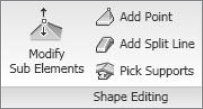
- Modify Sub Elements
This tool allows you to direct edit element geometry using selection and modification of points (vertices) and edges.
- Add Point
This tool allows you to add points on the top face of a roof or floor. Points can be added on edges or surfaces.
- Add Split Line
This tool allows you to sketch directly on the top face of the element, which adds split lines to the floor and roof so that hips and valleys can be created.
- Pick Supports
This tool allows you to pick linear beams and walls to create new split edges at the correct elevation automatically.

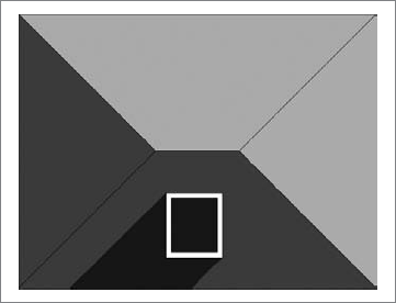
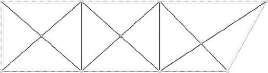
Let's do a short exercise that shows how to make a sloped roof like the one in Figure 13.20 (shown in plan view).
Follow these steps:
Open
Modifying Roof Shape start.rvtfrom the book's companion web page (www.sybex.com/go/masteringrevit2010).Select the roof that has already been prepared for you.
From the Shape Editing panel, activate the Add Split Line tool (note that the color of the rest of the model grays out while the roof lines are dashed green).
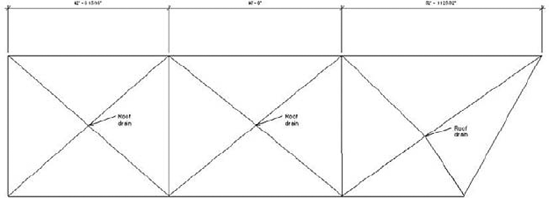
Draw ridge lines to divide the roof into areas that will be independently drained. The ridge lines will be drawn in blue color.
Using the same tool, draw diagonal lines within those areas to create the valleys. Make sure you zoom in closely when drawing the diagonal lines, so to be sure that you are snapping in the exact same diving points. (Should you notice that you have not snapped well, select the Modify Sub Elements tool, delete the incorrect segments, and try again.)
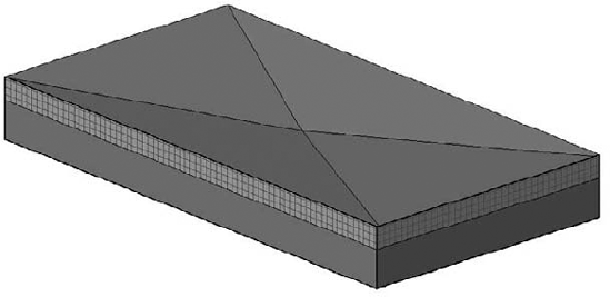
You have split the roof surfaces into many subfloors, but they are still all at the same height and inclination. You should have a roof that looks like Figure 13.21. Take care when sloping structures using this method; the structural thickness decreases with changes in slope. Press Esc to exit editing mode.
To add a slope, you need to edit the height of the drainage points. Tab-select the crossing point of the diagonals. New controls that allow you to edit the text appear, and you can either move the arrows up and down or type a value for the point height. As shown in Figure 13.22, type −0′5″ (−13cm).
Repeat steps 1–7 for all three drainage points.
If you need to move the point to another position (perhaps to accommodate what's happening in the room below the roof), select the point and drag it.
Make a section through the roof—if possible, somewhere through the drainage point. Open the section; change the detail level to Fine to see all layers. The entire roof structure is now sloped toward the drainage point.


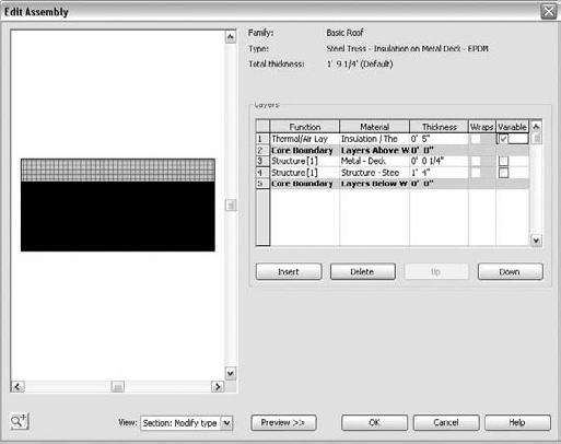
What if you wanted the insulation to be tapered but not the structure? For that, the layers of the roofs can now have variable thickness. Let's see how to apply a variable thickness to a layer.
Select the roof, and navigate to its type properties to edit its structure.
Activate the preview. You will notice that in the roof-structure preview, you do not see any slopes. That is correct and will not change. This preview is just a schematic preview of the structure and does not show the exact sloping. Look for the Variable column under Layers (see Figure 13.23). This allows layers of the roof to vary in thickness when slopes are present. Check Variable for the insulation material.
Go back to the section view and take a look at the difference that this change provoked. As you can see, only the insulation is tapered now, while the structure remains flat.

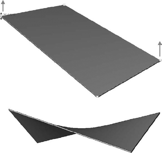
Warped surfaces can also be created using this tool. Using the Roof by Footprint method, draw a flat roof, uncheck Defines Slopes, and then select the roof. Using the Modify Sub Elements tool, you can start moving edge points up and down (Figure 13.24).
- Understand the various roof creation methods.
There are multiple methods for creating roof forms in Revit, and you should become familiar with each.
- Master It
When would you use a Roof by Extrusion method?
- Create all kinds of roofs.
Roofs are an integral part of any building. Knowing how to create them in a variety of shapes and sizes is critical to the success of a project.
- Master It
In the early design phases of a project, you are exploring a variety of roof forms for your building. Create the base building form and explore different roof options and shapes. How would you go about exploring a variety of roof shapes?
- Work with advanced roof and floor shape editing.
Roofs are another seemingly simple element that presents architectural challenges, and Revit has tools for them.
- Master It
You are working on a flat roof retail project, but the roof is not really flat and will need to drain. Using Revit roof tools, how would you go about modeling this?