In the previous chapters, we covered basic modeling techniques for constructing a simple building. We skipped over many additional features to give you a handle on essential workflow, the user interface, and modifications to the model. In this and the following two chapters, we'll cover advanced features that are available any time you're modeling in Revit. As you'll see, with a little refinement and creativity, you can create a wide range of building components with the standard tools.
In this chapter, you'll learn to:
Use advanced modeling techniques for standard walls
Use advanced modeling techniques to create stacked walls
Use advanced modeling techniques for curtain walls
Walls are made from layers of materials that represent the construction assemblies used to build real walls. In Revit, these layers can be assigned functions that allow them to join and react to other similar layers, so that when walls, floors, and roofs meet you get the expected representation. The wall core is one of these special layers, and understanding its behavior will help you when designing and editing your walls.
Revit has a unique ability to identify a wall core. As you will see, this core is much more than a layer of material. Every wall type in Revit has a core material with a boundary on either side of it. The core (the layers between the two boundary lines) defines the structural part of the wall and influences the behavior of the wall and how it interacts with other elements in the model. The core of a wall creates references to which you can dimension, designating the location of structural wall components as separate from the finish materials. The core boundary can also be used as the location definition when drawing host elements (walls, floors, ceilings, roofs). For example, you can constrain a floor sketch to the structural stud layer of walls by using the wall-core boundary to create the sketch. If walls change size or types are swapped, the floor sketch maintains its relationship to the core boundary and will automatically adjust to the new wall.
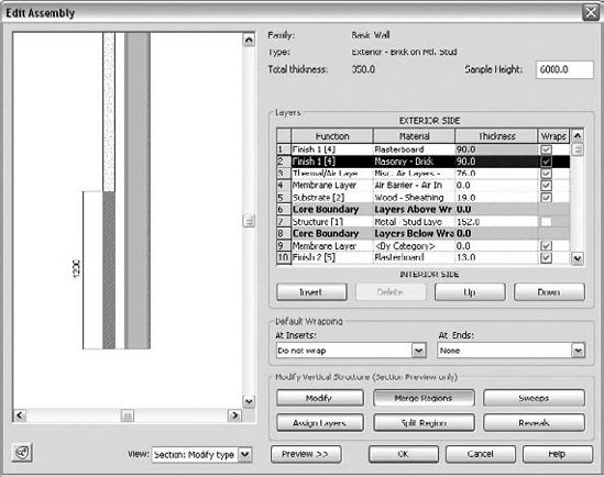
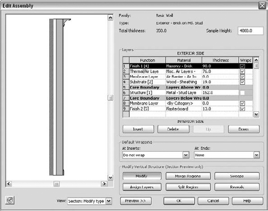
To access and edit wall-core boundaries and material layers, select a wall and choose Element Properties
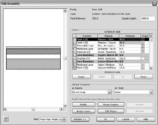
Figure 12.1. The Edit Assembly dialog box of a wall type lets you define the construction layers of a wall.
To get a feel for how core layers are used in relation to a floor, start a new session of Revit and follow these steps:
Open a new project, select the Wall tool from the Basic tab in the Design bar, and draw a simple rectangular floor plan. Prior to drawing it, from the Type Selector select a multilayered wall type in order to understand the value of the exercise—the Brick on CMU wall type works well. Draw at least four connected walls that represent a simple floor plan.
Use the View Control bar to switch to fine or medium detail view so you can see the wall layers. (In coarse views, wall layers are never displayed.)
On the Home tab, select the Floor tool, and from the Draw panel keep the default Pick Walls option, and on the Options bar, check the Extend into Wall (to Core) option.

Position your cursor over an edge of the wall (do not click yet), press Tab to highlight all connected walls, and then click to select, and then zoom in. A boundary line indicating the shape of the floor will be created. This line indicates the position of the floor boundary relative to the wall—it's drawn at the exterior edge of the wall core. Make sure you've selected all walls as a reference to create the floor and click Finish Floor.
Create a section through the wall and open the section view. Again, make sure your view level of detail is set to medium or fine. You'll see the edge of the floor and how it aligns with the wall construction. Figure 12.2 shows the sketch in plan and how the floor looks when finished in section.
If you change the wall type later on or move its position, the floor will update to maintain its position relative to the wall's new core position.
Having clean and legible drawings is important when representing construction design intent. To this end, Revit provides a wall layer priority system that intelligently manages the cleanup of wall layers between touching and/or intersecting multilayered walls. Revit provides six functions (levels of priority), with Structure having the highest priority (Figure 12.3).
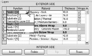
When you create a new wall type and begin defining and adding layers to the wall, you need to assign a material, thickness, and priority to those layers. When you're assigning a priority, think about the function of the layer in the wall—is it finish? Substrate? Structure? This decision will help Revit understand your intent and help clean up your wall joins down the road.
If you encounter situations in which the automated wall cleanup doesn't correspond to your expectations, a tool is provided that allows you to cycle through a range of possible layer configurations using the Wall Joins tool, located on the Modify tab.

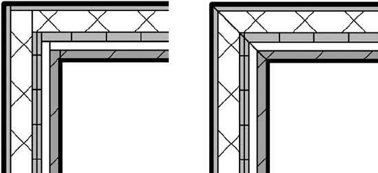
In some cases, you will want to override the intelligent wall cleanup that Revit provides. For example, a nonrated partition should not interrupt the gypsum board in a fire-rated wall. The Disallow Join option lets you create this condition. To access this command, right-click the blue control dot at the end of any wall and select Disallow Join from the context menu. Doing so breaks the auto-join cleanup. Figure 12.5 shows the default cleanup (left) and the same join after disallowing the join and adjusting the wall end (right).

A wall on which Disallow Join has been applied displays an Allow Join symbol upon selection (Figure 12.6). This is to give you a visual aid so you know when a wall has been explicitly set to not join. Note that the symbol only appears when a single wall has been selected.

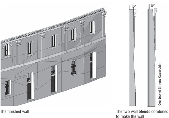
Walls in a building, especially exterior walls, are often composed of different wall types, made out of different material combinations and with different widths that stack one on top of another over the height of the façade. At the very least, most walls sit on top of a foundation wall. You can create such walls by creating individual walls of different types at different heights, but if you want an intelligent relationship among all different wall types that make up one wall and that act together as one wall (for example, the foundation wall moves and you expect walls on top of the foundation to also move), a stacked wall might be a good way to go.
Stacked walls allow you to create a single wall entity composed of different wall types stacked on top of each other. In order for you to construct stacked walls, some basic wall types need to already be defined in your project. To understand how stacked walls work and how to modify one, follow these steps:
Open a new session of Revit, and make sure three levels are defined. (If you don't have three levels defined, switch to an elevation view, add a few new levels, and then go back to your floor plan view.)
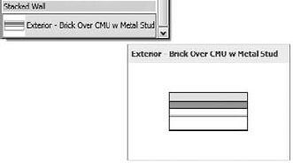
Pick the Wall tool on the Home tab and select Stacked Wall: Exterior - Brick Over CMU w Metal Stud located at the bottom of the list in the Type Selector, as shown here:
In the Element Properties dialog box, click the Edit Type button and then duplicate the wall type to create a new stacked wall.
Edit the structure parameter and click the Preview button to see the wall in section (Figure 12.7). When you're editing the Stacked wall type, you'll notice that the user interface is slightly different from when you're working with a basic wall. Rather than editing individual wall layers, in this dialog box you are editing Stacked wall types.
Click the Insert button to add a new wall. A new row appears in the list and allows you to define a new wall. Select the Generic wall type from the Name list, and set the Height value. With a new row selected, click the Variable button. This will allow the wall to vary in height to adjust with level heights. Click OK in each dialog box to return to drawing the wall.
Go back to your level 1 plan view and draw the new wall, setting its top constraint to Level 3 using the Options bar.
Cut a section through the model and change the heights of Level 1 and Level 3 to see the effect this has on the wall. (Make sure the level of detail is set to medium or fine so you can see the wall layers.) You'll see that changing Level 2 does not change the bottom walls because they are fixed in height. However, changing the height of Level 3 changes the height of the variable wall (Figure 12.8).

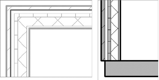
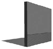
Walls are often complex and articulated in their composition. Cornices, reveals, corrugated metal finish, and other projections are used all the time. Some wall finishes have more than one material on them, and they can be flush or of different thickness. Revit can accommodate any of these types of design articulation in smart wall assemblies. Some examples of such walls, called "compound walls" by many Revit users, are shown in Figure 12.9.

From the Edit Assembly dialog box of any basic wall type, you can enable a preview of the wall. This preview allows you to view the wall in either plan or section. When the section preview is active, additional tools also become active and allow you to place geometric sweep and reveal components on the wall (Figure 12.10).
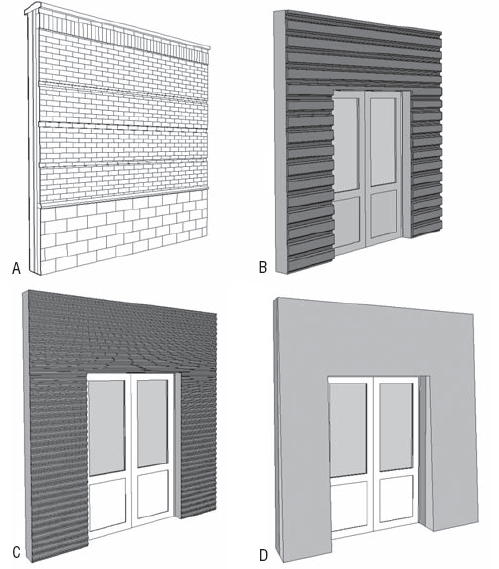
Figure 12.9. Compound vertical walls: (A) brick wall with horizontal sweeps, reveals, and a top finish; (B) compound wall with aluminum corrugated finish, trapeze-shaped; (C) compound wall with aluminum corrugated finish curved; (D) compound wall with slanting wall finish.

Now, imagine a case where you need to create a wall that has two different material finishes that are flush aligned, as seen in Figure 12.11.
Select a multilayered wall as a base and duplicate it to create a new wall type.
In the wall's Edit Assembly dialog box, switch the view to show a section view of the wall.

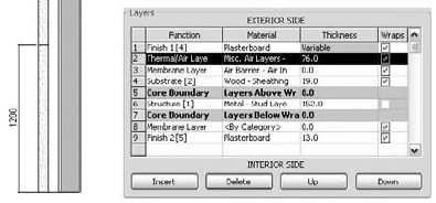
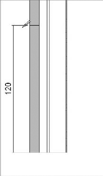
In this exercise, the exterior wall layer is plaster, but what you need is the lower 4″ (120cm) to be brick and to keep the walls flush with one another.
Place your cursor at the beginning of the exterior finish layer. This highlights the wall component in the section preview. Select the Split Region tool and split the layer at the 4″ (120cm) height (Figure 12.12).
The moment you split the layer, you will notice that the Finish layer reports a thickness of 0.00, meaning that it is variable.
Add one more layer. Use the Insert button and add that layer right after the first exterior finish layer. Change its function to Finish 1, its material to Brick, and its thickness to 0.

Place the cursor at the front of the row of the new material and select it. This highlights the material and shows a thin red line in the section view (Figure 12.13).
After adding that layer, click the Assign Layer button and select the portion of the wall that you wish to assign the zero thickness layer to (in this example, the lower portion).
The result is that the selected portion of the wall has the new layer assigned and your wall exterior face shows two different materials.
While working on a complex compound wall, you might have a situation where you need to merge horizontal or vertical wall layers that already exist in the wall. For that, use the Merge button and select the line between two layers. Once the cursor is over a line between two layers, an arrow indicating which layer will override the other one during the merge shows up, as shown in Figure 12.14.

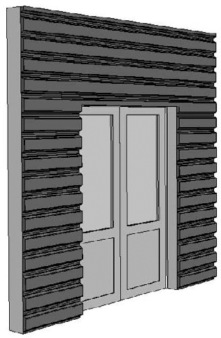
Materials are detailed at insert conditions (where doors, windows, and openings are placed in walls) depending on the construction type, building conventions, and aesthetics. For this purpose, Revit provides Layer wrapping options in the wall Edit Assembly dialog box; however, they aren't sufficient to accommodate a complex wrapping situation specific to a particular door or window. To achieve more control over these construction conditions, you need to set parameters in the window or door family itself.
In the Family Editor, you can assign a Wall Closure property to reference planes. This parameter defines a plane in the window family to which wall layers can wrap to.
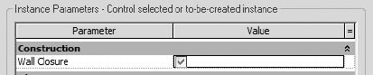
In a door or window family, check the option Wall Closure in the Element Properties dialog box for the reference plane. This means that the exterior wall layers that have wraps assigned will terminate at this reference plane. The effect can be seen in Figure 12.15.
Many walls have linear embellishments that are attached or embedded in the construction. Cornices, brick soldier courses, and reveals are all examples. Using basic walls, you can add these elements directly into wall types.
Clicking the Sweeps or Reveals button in the Edit Assembly dialog box opens a new dialog box where you can define profile families to use as sweeps or reveals.

These are 2D shapes made out of simple lines and then swept along the length of the wall at a specified height. Many profiles representing cornices, skirting, and chair rails ship with Revit, but if you need to create a custom profile, you can use the Profile Family template. Open the Application Menu and choose New
Click the wall tool from the Home tab, then click the Type Properties button in the Element Types dropdown menu, and then duplicate the type.
Open the Wall Assembly dialog box.
In the preview view, switch to section view. The six Modify Vertical Structure options become active at the bottom of the dialog box.
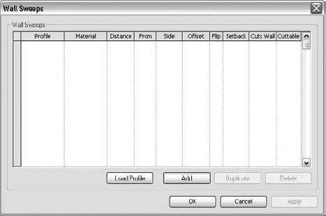
Click the Sweeps button to bring up the Wall Sweeps dialog box, shown in Figure 12.16.
Click the Load Profile button, browse to the Profiles folder, and load these two profiles:
Cornice profile: Traditional (1)
Skirting profile: (Base 2, Ogee or similar)

Click the Add button. This adds a row in the dialog box that lets you select one of the loaded profiles and set its position relative to the wall geometry.
Add both profiles. Set the Traditional profile's From value to Top and the Ogee profile's From value to Base. Doing so attaches the profiles to the top and bottom of your wall. Figure 12.17 shows the profiles attached to the top and bottom of the wall.
Click OK. Draw a segment of this wall in the drawing area. Check out the wall in section and 3D views to see the result (see Figure 12.17).
Using the same principles outlined for adding traditional elements, you can get creative and add any type of profile you want. Figure 12.18 shows a wall with corrugated siding added as an integrated wall sweep.
Reveals can be added to a wall using the same workflow you use with sweeps; the only difference is that the profile is subtractive rather than additive.
When you're working on traditional architectural projects, the wall sweeps usually wrap around door openings in thick walls. Revit can accommodate that using the Change Sweep Return command. To understand this feature, follow this simple exercise:
Open a new session of Revit and place a generic wall. Switch to the default 3D view.
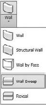
Rather than placing a sweep in the wall type (as we just did), you can use another method for placing sweeps: the Wall Sweep tool located in the Wall drop-down list.
These sweeps can be placed either vertically or horizontally using the contextual ribbon.

Add a horizontal sweep to the middle of the wall. Use the temporary dimensions to place the sweep at the desired height.
Choose the Wall Opening tool, located on the Modify tab.
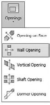
Select Wall Opening, and using this tool, draw an opening that intersects the sweep (Figure 12.19).
Select the sweep—it will display a blue grip at the end (the edge of the opening). Click the Modify Returns button in the Modify Sweeps contextual tab. Also take notice of the Options bar, where you can also set the angle of the return or decide to make a straight cut. The cursor turns into a knife symbol, and when you click somewhere on the profile it creates a new segment that can be wrapped around the edge of the opening. Press Esc or use the Modify tool to exit the command. You will need to zoom in close to the end of the sweep to really see the effect. (If you zoom very closely, the lines might become thick and ugly. In that case, click the Thin Lines Mode button on the View tab.)
Select the sweep again, and drag the control to adjust the length of the sweep. Figure 12.20 shows how the return can be modified.


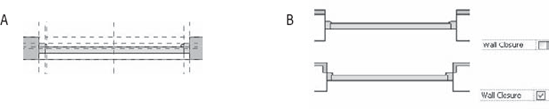
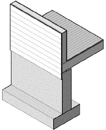
In many construction scenarios, you need layers of materials to extend beyond the base of the wall. A typical example is the extension of sheathing and siding on an exterior wall (Figure 12.21). Letting layers extend requires you to unlock the bottom edges of the wall from the sectional preview in the Edit Assembly dialog box. Once the layers have been unlocked, an instance parameter of the wall becomes enabled, either Base Extension Distance or Top Extension Distance (depending on which edges you unlocked). This value can be entered directly in the Element Properties dialog box or adjusted graphically when you select the wall by dragging the small blue triangle control at the bottom of the unlocked layer.
Follow these steps to enable the Base Extension parameter of a wall:
From the Home tab, create a new Wall. Select it and duplicate it by editing the type. Name it Exterior wood siding.
Select the structure parameter to open the Edit Assembly dialog box.
Add a new layer to the exterior of wall, set its function to Finish (4), use the material siding - clapboard, and give it ¾2 thickness.
Open the preview and look at the section view. Zoom into the bottom of the wall.
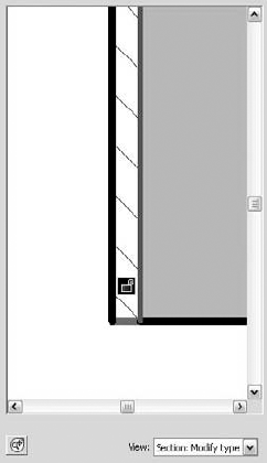
Select the Modify button located in the dialog box, and then click on the bottom edge of the exterior siding layer. Click the padlock icon to unlock the layer (Figure 12.22). Note that if you wanted to unlock additional layers, they all need to be adjacent—you cannot, for example, extend layers on either side of the core.
The layer is now unlocked. Click OK twice to get back to the Instance Properties dialog box. You'll see that the Base Extension Distance parameter is now enabled. Type in −10″ for this parameter, and check the wall in 3D. You'll see that the wood siding layer is now extending 10″ below the level shown in Figure 12.23.

When you're working on traditional architecture or restoration of historic buildings, you often need to create walls that are irregular in shape. The Model In-Place tool, found in the Component drop-down on the Home tab, lets you address such wall styles. Figure 12.24 shows an example. This tool allows you to draw solid geometry using one of four modeling methods. Each created form is assigned a specific category that is later used to control visibility and behavior in the model. For example, assigning a sweep to the category Wall allows the wall to host inserts such as windows and doors.
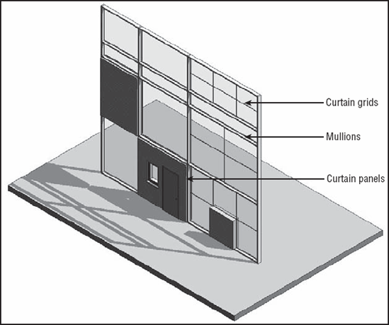
Curtain walls in Revit are unique wall types that allow you to embed divisions, mullions, and panels directly into the wall. They have a distinct set of properties, but still share many characteristics of basic walls.
- The curtain wall
A curtain wall is drawn like a basic wall and is available in the Type Selector when the Wall tool is active. It has top and bottom constraints, can be attached to roofs, can have its elevation profile sketch-edited, and is scheduled as a wall type.
- Curtain grids
These are used to lay out a grid that defines the physical divisions of the curtain wall. The layout grid can be designed freely as a combination of horizontal and vertical segments or can be a type with embedded rules that specify regular divisions. Figure 12.25 shows a typical grid division and expressive curtain panels in between.
- Mullions
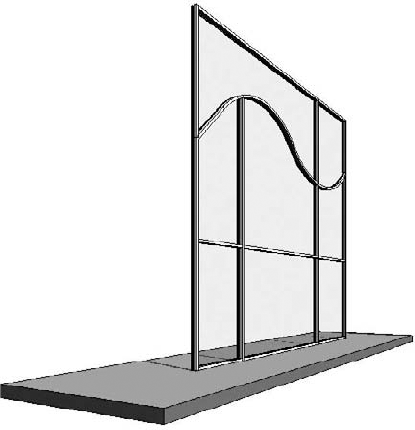
These represent the metal profiles on a glass façade, and in Revit they follow the geometry of the grid. They can have any shape that is based on a mullion profile family. Mullions can be vertical or horizontal. If you have a playful spirit, however, you can make curved mullions as shown on Figure 12.26.
- Curtain panels
These fill in the space between gridlines and are always one of the following:
- Empty panels
No panel is placed between the grids.
- Glazed panels
These can be made out of different types of glass that can have any color or transparency.
- Solid panels and panels with wall types
These can take on any geometry you wish and thus create the most interesting structures, like the one shown in Figure 12.26.
- Wall types as infill
You can also choose from the Type Selector a wall type to fill the space between the gridlines (mullions). All wall types in the project will be available for your selection. Adding a wall type is usually a typical case in office partitions where the lower portion is a parapet wall and glass fills the upper portion of the metal stud wall.
In this exercise, we'll walk through the creation of a simple curtain wall. To draw a curtain wall, you can either draw a standard wall and then change its type to Curtain Wall or select a Curtain Wall type from the Wall Type Selector first. Follow these steps:
From the Home tab, select the Wall tool.
From the Type Selector, select Curtain Wall 1.
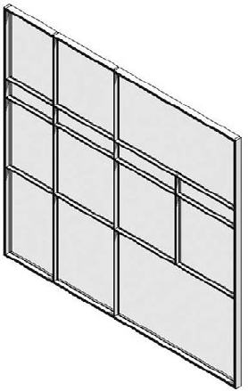
In the Level 1 plan view, draw a simple curtain wall (Figure 12.27). Use the wall type Curtain Wall 1.
Toggle the view to see the result in 3D.
Divide the wall into panels using the Curtain Grid tool on the Home tab. Position your cursor over the edges of the wall to get a preview of where the grid will be placed. (Selecting a vertical edge places a horizontal grid, and selecting a horizontal edge allows a vertical grid.) Revit has some intelligent snapping built into grid placement that looks for midpoints and points that will divide the panel into thirds. Place the grid so that you get something like Figure 12.28.
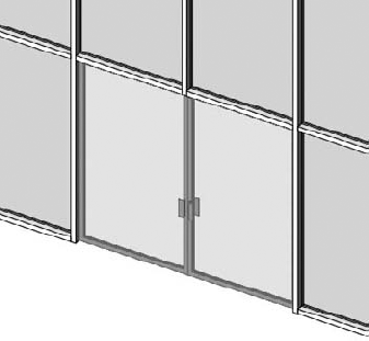
Place mullions on the wall. You can place one mullion at a time by selecting separate grid segments. If you want to apply the same mullion on all segments, hold the Ctrl key and click a gridline to select all segments and apply the mullions. With mullions placed, your wall should look like Figure 12.29.
Let's say you want to add more mullions, but this time you don't want them to extend the entire height of the curtain wall. Select the Curtain Grid Line tool on the Home tab, and place new grids (Figure 12.30).


Remove the top and bottom segments, and then add mullions (Figure 12.31).
Curtain panels fill the space between the curtain grids and mullions. These elements are created in the Family Editor using the Curtain Panels family template. Access them by choosing Application Menu
Figure 12.26, earlier in this chapter, shows some very creative curtain panels.
Revit provides specially tailored selection options in the context menu to aid with workflow and interaction when you're working with curtain walls.
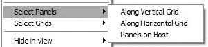
When you hover the mouse over or select an element in a curtain wall, take note of the status bar in the lower-left corner of the screen: it tells you exactly the type of element you're about to select or have already selected. Depending on what the mouse is hovering over, various selection options are available. The elements you can select include the following:
The entire curtain wall entity (indicated by a green dashed line surrounding the curtain wall)
A gridline
A mullion
A curtain panel
To select the element you want, use the Tab key until that element is highlighted.
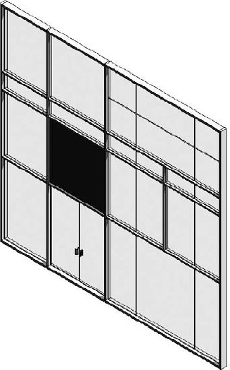
Curtain walls can host specially designed doors and windows. Keep in mind that standard doors and windows cannot be hosted by a curtain wall. These specially designed elements are recognizable in the library by a name that indicates they are curtain wall doors or windows. Revit schedules them as doors and windows, but their behavior is dependent on the curtain wall. Curtain wall doors and windows adapt their width and height to fill in grid cells. Essentially, they behave exactly like panels—they've just been made to appear and schedule as doors or windows. To insert a door within a curtain wall, choose Component
Look at the complex-shaped curtain panels in Figure 12.33. You may think, "Oh, I can never do that!" Well, Revit can help you do it—and do it easily. The creation principle behind any of these types of curtain walls is the same as you learned in Chapter 10. By being smart about nesting and linking parameters, it is possible to build sophisticated curtain panel families.
- Use advanced modeling techniques for standard walls.
Many design situations require more than just the basic wall features; learn to use the more advanced Revit tools.
- Master It
A design calls for a horizontal soldier course in a brick wall every 12″ on the façade. Using Revit, how would you build this into a wall element?
- Use advanced modeling techniques to create stacked walls.
Walls along a building façade usually have different construction layers from foundations to the top of the building. Stacked walls allow for a single wall to be constructed with varying wall types along its height.
- Master It
You have a building project where you are still experimenting with a number of floors but have already defined the wall types for the foundation, typical floor, and the attic and have combined them in a stacked wall type. How do you define the stacked wall so that it will accommodate middle floors with varying heights?
- Use advanced modeling techniques for curtain walls.
Curtain walls find their way into many architectural projects and designs. Knowing how to manipulate curtain walls in Revit is a key piece of the software for many design solutions.
- Master It
You've got to add a doorway to a storefront façade you've made. How would you go about doing this?