
In this chapter we'll explore scenarios in which elements in a building repeat, and you'll learn how to take advantage of some tools in Revit to help your workflow be more efficient and less prone to error. The tools we'll explore are called groups and links—tools specifically designed to support design and propagation of repetitive entities, which can range from entire buildings to individual rooms to furniture arrangements.
Both of these tools require an understanding of some basic principles that will help you make decisions about when and where to engage these features in a design. We will introduce the concept behind each tool and present a series of use cases in which groups or links provide a valuable solution to a design problem.
In this chapter, you'll learn to:
Many architectural projects deal with the design and organization of repetitive elements. The concept of a modular unit that is repeatable has been one of the more important principles of architecture and continues today in the form of housing, hospitals, schools, and office buildings. A repetitive element can be found at nearly every scale: from entire buildings to housing units; from hotel rooms, classrooms, and hospital rooms to bathrooms, closets, and furniture layout.
In each case, the basic requirement is to group a collection of elements that is repeatable so that later in the design process any change to the module will be propagated to all the other instances (copies) of the module. This propagation results in huge time savings, as you don't have to manually update the model, element by element. This also guarantees consistency and means there are fewer changes to correlate as documents are reviewed.
At the same time, flexibility must be built into the tool to account for edge conditions where the repetitive unit needs to stray away from base without breaking its relationship to the essential nature of the module. Revit is remarkably well suited to meet both these needs and support a diverse set of design requirements.
Groups significantly improve your workflow when you are working with collections of elements that need to be repeated throughout a project.
When a collection of related elements is made into a group, it becomes possible to manage and change any single instance of the group and have the changes propagate throughout the entire model—all in one interaction. It is also possible to execute a change on one group instance only and not have that change propagate. As you will see, Revit was designed to be flexible. It lets you group elements in a project or even inside a family and use it to quickly lay out entire floor plans. You can also save groups and reuse them in other projects, making them quite versatile.
As we've discussed previously, the Revit categorization schema is intelligent: objects know what category they are and in what views they are visible. This directly impacts how groups are created and organized. For example, model elements (walls, floors, furniture, etc.) are grouped as model groups, and 2D, view-specific elements (dimensions, annotations, etc.) are grouped as detail groups. There is also a hybrid category called attached detail groups, which relates grouped details to a specific model group. If you create a group that contains both types of elements (model and annotations), Revit automatically stores this group as a model group with an attached detail group for the view-specific information. Keeping tags and keynotes associated with a model element in a group is an example of this. That said, there are certain conditions where information cannot be attached within a group. For example, if a dimension between two walls is added to a group but only one of the walls is in the group, Revit cannot attach the dimension. The dilemma is obvious: when new instances of the group are placed, where should the dimension go in the absence of the original, ungrouped wall? Remember that dimensions, tags, and keynotes refer to real model elements and cannot exist without their references (hosts).
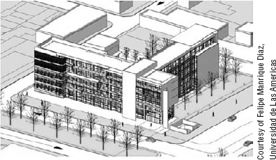
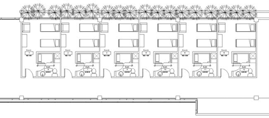
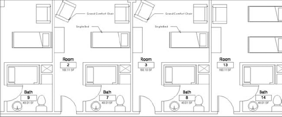
Most architectural firms have projects where repetitive units are used throughout the design. In our first example, we will work on a day-care center for children with cancer (Figure 20.1). The design calls for many typical bedrooms, most of which will be the same size and have the same accommodations (bed, bathroom, furniture). The ability to design, iterate on, and manage all these bedrooms will be a major part of the project, which also has to be easy to maintain, schedule, and update.
We will first work with groups to solve this design challenge; later we will look at the same issue from the vantage point of using links and examine the differences between the two approaches. As you will see, each method leads to different results.
As soon as the building design is roughly oriented on the site and you start laying out the modules inside the project, you can immediately take advantage of group functionality by defining the basic room unit that will repeat. Later, you can add more content in one instance of the group, which will then populate into other instances of the group that are placed throughout the project.
Early on, you'll work with walls and rooms to create reliable area schedules that will show you how the design is stacking up against the program requirements. You'll also take full advantage of BIM by keeping all information centralized in one file. Using links (external file references) rather than groups, you would not get these benefits.
Let's step through a workflow using groups to lay out bedroom units.
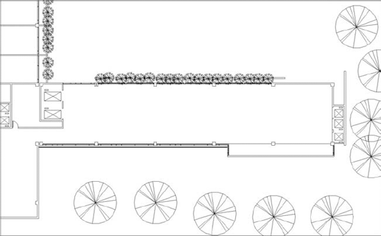
Open the
Chapter_20_Model_Groups_Start.rvtfile from the book's companion web page (www.sybex.com/go/masteringrevit2010). The project should open with the plan view (Level 3) shown in Figure 20.2.
When creating the group, you only chose one of the perpendicular walls (the one on the right side) because you need to repeat the module along the length of the space. If you added both perpendicular walls to the group, you would end up with overlapping walls when the unit was copied along the length of the building. This would result in lots of warning messages to deal with. Not taking these warnings into account would later affect the scheduling of walls, so you need to be smart about how you make your groups.
Once the Group tool is activated, you'll be asked to name the group. As soon as this task is finished, the new group will appear in the Project Browser under Groups

Before you make any changes to the group, take a look at a symbol showing the group origin (Figure 20.4).

The group origin symbol (insertion point) is placed at the middle of group geometry by default, but you can change it to what you feel will be the most appropriate and practical point of insertion when you pick the group to reuse and place again in the project. Move the group origin symbol to the intersection of two walls, which will help when placing new instances of the group. To do so, place the mouse over the intersection of the X and Y axes and drag it to a new position, or use the Move tool.

There are many possible ways to proceed in the group placement process. You can insert more instances of this group along this wing of the building using the Copy Multiple Instances tool or the Array tool. An alternate approach is to use the Project Browser, and drag and drop the group instances into the view (Figure 20.5). Let's see how this works.

For this exercise, drag and drop from the Project Browser to place new instances of the group in the floor plan. (You can place groups in 3D views as well, but the common use case is in plan.) Once you drag the group from the Project Browser into the view, release the mouse button and take your time zooming in to the insertion point in order to get the correct snap without stressing your hand.
After choosing the insertion point, you'll see that the walls belonging to the group clean up with other walls that do not belong to the group. This is perhaps the most profound difference in behavior between groups and links (which we'll get into a bit later): essentially, linked elements cannot interact with elements in the model they are linked to, while walls belonging to a group will clean up with walls from the main model.
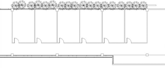
Continue to place groups until you arrive at a more developed floor plan. To speed up the process, try using the array command to array the group across the floor plan—just be sure to un-check the Group and Associate option in the Options bar, or you'll end up with redundant groups. (Figure 20.6).
With the basic unit established, you can start adding more complexity and really see the power of groups. Because all the groups are instances of the original model group, any changes to this group will affect the others. Select any one of the groups in the floor plan, and take a look at the Group panel in the ribbon:

To change a group during the process of design, select the Edit Group button. This takes you to the Group Edit mode, where a new Edit Group ribbon panel will appear.


The drawing area will turn a pale yellow, indicating that you are now in a special Group Edit mode (Figure 20.7). The group editing panel appears appended to the end of the ribbon.
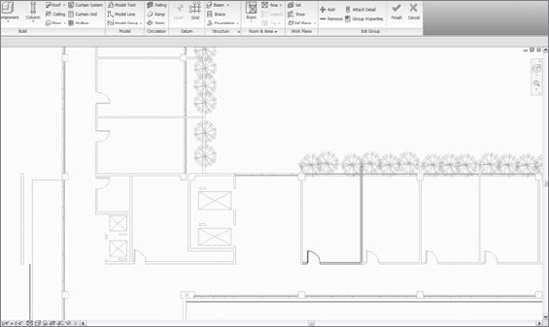
Figure 20.7. The Group Edit Mode is indicated with a pale yellow coloring of the drawing area, signifying the special mode. The floating group editing bar offers group-specific tools.
While in Group Edit mode, move the door to the other side of room. When you click Finish, all the other group instances will update with the new door location (Figure 20.8).
The need to change a design is quite common throughout the lifecycle of a project; projects evolve over time and are never complete with the first iteration. Groups are not fixed entities and are easily edited. You can make changes and add new elements to a group while in Group Edit mode seamlessly and at any point of your design process. You can access the modeling commands while editing the group, in order to add these elements. If you need a new component added to the group, it's just a matter of creating it while in Group Edit mode.
The Group Edit toolbar provides the following features:
- Add
This allows you to add any element from the project as the current object in the group.
- Remove
This allows you to remove elements from the group.
- Attach Detail
This allows you to add view-specific annotations, which will become attached details and will be displayed as a subcategory of the model group in the Project Browser.
- Group Properties
This provides access to the Group Properties dialog box, where you can edit the group's name. The level the group is attached to and its offset from that level are presented but not editable.
At this stage, you can generate an area report to check the requirements, and the design can continue to evolve. You will now add the bathroom and some furniture. Both of these will expand on the concept of groups by making new groups and nesting them inside of the unit group. You'll also add some details (dimensioning) to create an attached detail group. To conclude, we are going to explore alternatives in the room's layout.
The next step involves adding rooms so that you can schedule the room units by areas or by room type.
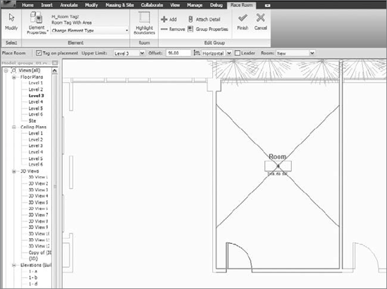
Select the unit group, and then click Edit Group in the contextual tab. Once in Group Edit mode, use the Room tool (on the Home tab) to place the room. It will automatically be added to the group (see Figure 20.9).
Click the Finish button on the Edit Group panel to finish the change to this group and populate the change into all other instances of this group.
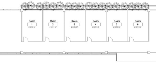
To verify that the rooms now exist, tag them using the Room tag command on the Room and Area panel on the Home tab, as shown in Figure 20.10.
Note that when you add a room tag to a grouped room, the room will get propagated but not the tag. You will still need to manually tag all the rooms in the copied groups.
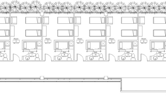
To see how many rooms you have and their areas, create a room schedule that includes name, number, and area (see Figure 20.11). This can be useful for making decisions about the composition of a floor plan and seeing if you are meeting program requirements as you make changes to the design.

Often, repetitive units can be a part of other repetitive units. For example, a standardized bathroom unit will repeat throughout many hotel rooms. To support this in an intelligent way, Revit offers a methodology of nesting a group into a group so that the integrity of the unit is maintained. The bedroom group we just created can be completed with the addition of a nested bathroom group and furniture group. As shown here, a nested group appears in the Project Browser as a subnode of its host group.
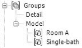
Following a typical workflow, you can start designing the bathroom by adding walls and plumbing fixtures. Once you've added new walls and fixtures, select and group them, as you did the initial walls (see Figure 20.12). You'll notice that walls in groups clean up with walls outside of the group, making the grouped wall interaction with walls outside of the group seamless.

To add the bathroom group that you just created to the bedroom unit group, select the group, click Edit Group, and use the Add button in the Edit Group panel. By selecting the bathroom group, you add it as a nested group in the Bedroom unit group. You will notice that a new entry appears in the Project Browser under the Bedroom Unit node.

Finish the Group Edit mode by clicking the Finish button. The bathroom will be propagated to all other instances of the group (see Figure 20.13).

Now that the unit is more or less complete, you can start adding some annotations and dimensions to the plan in order to better communicate the design. Begin by dimensioning and adding text or tags in one of the units. To repeat the dimensions in other units, you can again take advantage of group functionality.
Select a dimension and group it to make a new detail group. You'll be prompted to give the detail group a name. To then add the detail group to the model group, select the group and then click the Attached Detail Groups button in the Modify Model Groups tab. This opens the Attached Detail Group Placement dialog, where you can choose the detail group to attach.

To continue designing the unit, you can add furniture to one of the units. You can place the beds, dressers, and chairs and then group them and nest them just as you did with the bathroom.
What if you already have a similar grouping of furniture from a previous project that you'd like to use in this project? To use a group from another project, open the other project, right-click on the group in the Project Browser, and choose the Save the Group to File option in the context menu. This creates an RVT file of that group that can be reused in other projects. You can also copy/paste a group from one project to another.
To reuse a saved RVT file as a group, select Load as Group from the Load from Library panel on the Insert tab, as shown in Figure 20.15. The dialog box that appears has some special options that let you choose whether to include attached details or levels and grids when loading. If the Attached Details option is checked, you will import any details attached to the file, such as dimensions and tags. Levels or grids can also be imported with the group, if necessary, but don't bring in levels and grids if you don't need them.
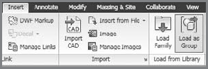
Load the file furniture.rvt to use it in this project.
The group will appear in the Project Browser and can be dragged into the view like any other group. Drag the group into the view and add it to the unit group. Once you do that, it will propagate to all the other units, as shown in Figure 20.16.
In just a few steps, you've developed quite a complex structure with extreme flexibility. Not only can Revit manage model and detail groups, but it can also work with different levels of nested groups within the main group. For example, if an alternative layout is needed, Revit provides tools that can facilitate a smart workflow. By right-clicking on the group's name in the Project Browser, you'll get a better picture of the possibilities (Figure 20.17).
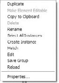
The options displayed here provide the following functionalities:
- Duplicate
This creates a copy of the group with a new name and allows you to edit a copy of the group without disturbing the original and affecting all other instances of the group. This is helpful when you need a significant geometric variation in design from the first group. You can then at any point swap groups using the Type Selector. Just keep in mind that groups swap out about their insertion point. So be sure that when you swap groups (using the type selector) they share an appropriate insertion point.
- Copy to Clipboard
This provides an easy way to choose a group and copy it to other levels.
- Select All Instances
This selects all instances of the group in the entire model. Use this to quickly make selections for the purpose of deletion or swapping.
- Create Instance
This provides an alternative means of placing a group. It's as if you were dragging the group from the Project Browser into a view.
- Match
This functions the same way as the Match Type tool. Enable the tool by selecting it. By first clicking Room Type A and then clicking a room of Type B, you can change Room B into a room of Type A. Another way of doing this would be to just select a group in the view and change the type directly using the Type Selector.
- Edit
This opens the group for editing in an independent session rather than in the active project. This allows you to see and edit the group in isolation without the clutter of the project.
- Save Group
This allows you to save the group as an RVT file and reuse it later in other projects. This option leads to a dialog box where the new file's name is by default the same as the group's name, and you can decide whether or not to include the attached Detail Groups as views.
- Reload
This lets you reload a group. Use this if you edited the group as a separate file and saved the changes, and now need to reload it to get the most up-to-date version. Reload is not automatic; you'll be prompted to locate the file on disk to do this.
In our example, you can duplicate the unit group, giving it a new name, and then make edits to the newly created group. You can then swap entire groups just as you would any other component in Revit (Figures 20.18 and 20.19). Thus, with just a few clicks, you can explore design variations and propagate changes quickly and reliably.

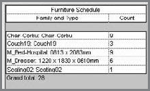
If you create a furniture schedule, you will be able to see easily how the changes to the design affect the quantities (Figure 20.20).
To understand the full potential of Revit groups, you should be aware of some other options. Let's consider a practical example. What would you do if you need one of the Room A groups to have eight pieces of furniture instead of nine? The intuitive answer would be to duplicate the group and just take away the chair while in the Group Editor. Although this option would work, it means generating an additional new group and thus additional information for the project to handle, thereby adding more complexity, which always makes the project more prone to performance issues.
Revit groups have a feature called Exclude, which basically takes away selected objects from selected instances of a group without altering the rest of the group's instances. The object is not actually deleted (you have the option to restore excluded objects); it is just deactivated in that group and removed from any schedules. This option is more powerful than just overriding the view by hiding individual elements using the Hide Graphics in View by Element feature, because overriding the view would not update your schedules.
Clicking the icon excludes the element, so it will no longer be counted in schedules (Figure 20.22).


You can always add the element back to the group by right-clicking and choosing Restore All Excluded or by clicking the icon again. Note, however, that the icon will not show up if you are in Group Edit mode.
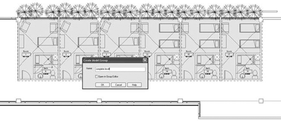
If parts of the whole floor plan need to be repeated on other levels, you can make a group out of many groups, generating a new high-level group in the Project Browser. For example, you can select the six bedroom-unit groups (also containing nested groups and attached detail groups) and make a new master group, which we have called Complete Level (see Figure 20.23).
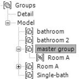
The result of this action is represented in the Project Browser, shown in Figure 20.24.
With the entire collection of rooms on the floor now in one group, you can select that group and copy it to the clipboard. From the Clipboard panel, choose Paste Aligned

To recap, we chose to leave the exterior wall outside of the group to treat it as a single element that spans many levels in the project. We proceeded to make a rough definition of the room unit, which was necessary to fill out the building's wing. If we had instead added a portion of the exterior wall to the group, our exterior wall would have consisted of many separate walls, which would violate typical workflows and expectations. By placing just the initial module, we were able to quickly assess the needs for circulation and elevator locations, generate area calculations, and evaluate the design.
Then, by nesting groups, we solved the whole bathroom design and propagated it to the other rooms in one interaction, and likewise the furniture layout. If we had wanted alternatives in the room's layout, a new group made from the previous group could have been created, modified, and swapped out. For more granular changes, such as removing a seat from one single instance of a group, the Exclude option could be used to avoid making unnecessary new group types.
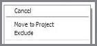
The ability to make the group a part of the project is a key feature of groups. If there is a slight variation in an instance of a group that requires moving one or more objects, you can select the desired element by right-clicking on it and choosing Move to Project. This option excludes the object from that specific instance of the group and puts it into the model, where it can be freely edited without editing the group. For AutoCAD users, the closest analogy to this is exploding a block.
Moving an Element in a Group to a New Location
In the bedroom design, the dresser needed to be repositioned in the last unit in the layout without making a brand-new group for such a slight variation. By tabbing into the dresser and selecting it, the designer was able to move it to the project using the context menu.
This action moved the element out of the group, allowing it to be relocated to a new position:

The left image shows the dresser before being moved to the project. The right shows the dresser moved to the project and then repositioned.
In terms of workflow, before deciding whether to move or exclude an element, the main question to ask is whether or not that change will be reused. Exclude and Move to Project are solutions for specific problems in an instance of the group, but that's where their whole power resides. Always remember that when you exclude an object, it also disappears from the schedule, whereas Move to Project does not affect scheduling at all since the object is still around.
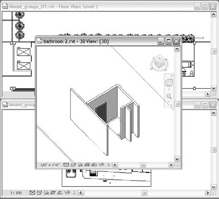
When you are working on a large file, it can be difficult to isolate a group for the sake of editing it. For example, when working in a complex building model where you don't want to be burdened with hiding unwanted elements to get a clear view of the group (Figure 20.26), you can use a feature that allows you to edit the group as a separate file. Since this option isolates the group in a single file, you can work from there and then save the file and use the Reload option explained previously. The Edit option that appears when right-clicking a group in the Project Browser opens the group as an independent file outside the project environment, similar to the way you can edit families independently of the project. You can have both the whole project and the single file open at the same time, working with changes that are reflected immediately after saving and reloading.
After editing the group, save it and then go back to the project and reload it from the Project Browser using the right-click context menu. All groups of that type will then be updated.
We have touched on detail groups, but let's look at them a bit more closely. You can create annotations to add textual descriptions, add dimensions to measure elements in a group, and then group them in what is called a detail group. The detail group can then be attached to instances of the model group. A detail group can be attached to a model group by using the contextual tab when a group is selected. This is a quick way to apply consistent annotations to many groups.
In Figure 20.27, a room is annotated, and then the annotations are grouped.

When you multiselect all the unit groups and click the Attached Detail Groups button, your recently created detail group will be applied to all your groups in one interaction (see Figure 20.28).
Here are some aspects to consider when working with groups:
When using groups on multiple floors (levels), the levels have to have the same floor-to-floor height if the groups are to work effectively. Currently, there is no way to make walls in a group taller from one floor to the next, so just be aware of that. Always remember that although you are working in a seemingly 2D floor plan, everything is 3D. You'll avoid propagation issues if the walls in groups have unconnected heights.
Placing multiple instances of a group affects the file size. The group is not a link but rather is an element repeated inside the project (instantiated). Once you load a file as a group, it is part of the project and will add to the file size as often as it is used.
If you need to have reduced file sizes, using links instead of groups might be a solution, although it depends on the applicability of the scenario in which you wish to use them, and most important, you should be aware of the consequences of using links.
Try not to mirror groups—create left and right versions instead. While this is more time consuming, it avoids mirrored elements that should not be mirrored (such as plumbing fixtures, equipment, and specialty furniture). As an example, mirroring hospital rooms may easily create inadvertent errors from a utility connection standpoint.
Keep nested elements and their hosts grouped together.
Groups are very processor intensive. You can quickly get to a point of diminishing returns (from a performance standpoint) when groups contain nested groups, or entire floors have been grouped. It works great when you need to disseminate large collections of elements. But editing groups and waiting for them to update can severely affect project workflow.
When you have worksharing enabled and you create a group, all the elements are assigned to the active workset. So although groups may contain elements on different worksets, the moment you ungroup and regroup that information is lost. So you might as well plan on assigning elements in groups to a single workset.
You've seen that Revit groups can be a powerful tool for streamlining the design workflow, but the performance hit you take from increased file size can be significant. Revit provides another tool that allows you to work with repeating elements and avoid the file size problem: links. Be aware that links have limitations that you might not be comfortable with, so make sure you understand these limitations before deciding to go with the linking method.
To show how links work, we'll continue with our example project.
When you select a group, you will notice that the Link button appears in the Modify Model Group contextual tab. When you click the Link button, the dialog box shown in Figure 20.29 appears. It presents two options that you need to understand: Create New and Use Existing. In other words, is the information contained in the link going to a new file, or will it be added to an existing file?
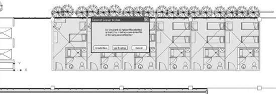
In this particular case, we are creating a new file, so Revit will automatically create a new file in the folder of the project (by default) and replace the group with a link in the exact same place (see Figure 20.30). The process does not involve any user action at all apart from clicking the Link button. This might look like the ultimate solution for managing file size. In certain cases this may be true, but let's look more closely at the implications.
Walls in a linked file will not create clean wall join conditions with the host file, which can make scheduling of rooms particularly difficult. In fact, the first thing you will probably notice once you convert the group into a link is that the walls belonging to the link do not clean up with walls belonging to the active host model, because joining between elements in a link and those of the project isn't possible. You can override this behavior by selecting the Room Bounding checkbox in the type properties of the link. This will allow the walls in the linked file to enclose space and let you place rooms.
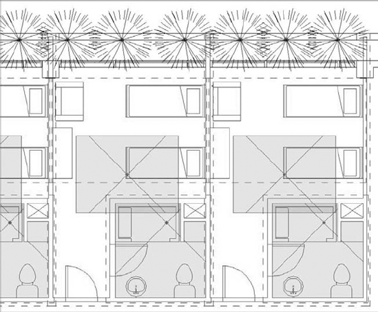
Figure 20.30. A group converted into a link on the fly. Note that the rooms no longer have boundaries defined by the walls.
If wall cleanups or definition of rooms are not a serious issue in your workflow (an example would be a renovation of an existing building), using links could be a good solution to help manage file size. Even so, it is nice to know that as soon as you bind the link (convert it back into a group), you'll get wall cleanup and valid rooms again.
Note that binding links will work on any instance of a linked Revit file. This brings the link file completely into the project file and severs the link to the external file. For AutoCAD users, the closest analogy is binding of XREFs.
Links are well suited for workflows where you don't need a tight connection between elements, such as linking entire buildings or site plans into your project file. Links are commonly used when working with the following kinds of projects:
Separate buildings on a shared site plan
A site plan and contextual masses
Large-scale divisions in building mass and program
Other disciplines (Structure and MEP)
In the following examples, you'll see various situations when linking files can be useful.
- Multiple buildings on a shared site plan
At Koolhaas's station complex in Lille (see Figure 20.31), there are buildings designed by other architects directly over the station's roof. Interaction among the models is important in order to identify heights and possible restrictions between the buildings. This interaction could easily be created by linking the buildings for coordination, with each model residing in a separate file. What's more, each building could also use nested links or groups. For example, when working on the building over the station, you could link the train station into your model. Within the train station could be links to mechanical system files. All of these elements would be visible in the main host file. This form of nesting keeps file size down and makes working manageable.
- Identical buildings on a shared site
Another use would be a project where a housing unit is duplicated many times on a site. For example, if you have three identical buildings, you would model one building, link it into a site file, and then make two additional copies. If you then edit the original housing file and update the link, all three instances of the linked file will update in the site file.

The linking method is not only applicable to buildings with repeating units but can also be used as a methodology for working in a highly coordinated way with other engineers and consultants using Revit Structure or Revit MEP. This workflow is designed as a fully collaborative use of BIM for all the disciplines. Using links, you can integrate structural framing, ductwork, and mechanical systems into your base architectural project for coordination. In a traditional process, this coordination was based on endless revisions, miscommunication, and colliding systems that ended up being resolved on-site during construction at tremendous cost. The Revit BIM platform provides transparent connections between Revit Architecture, Revit Structure, and Revit MEP. In fact, you can open a Revit MEP or Structure file in Revit Architecture because they are all based on the same technology. The only difference will be the available tools: with a Revit Structure or MEP file open, you'll be able to select and modify ductwork, for example, but you won't be able to make new ducts.
Linking different disciplines in Revit provides better coordination and even allows for collision detection. This toolset will not be covered now, but you should be aware that it is all possible in Revit using what are called Copy/Monitor and Interference Checking. For further reading on these subjects, consult the Revit help documentation.
To link an RVT file, choose Link Revit from the Insert tab. The dialog box involves some decisions in terms of how to position the linked model in a project and which worksets to open, as shown in Figure 20.32.
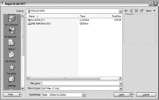
The positioning defines the location of the linked model inside the project and can be manually or automatically done. Automatic positioning of the link provides the following options:
- AutoCenter to Center
This aligns the 3D center points of both models.
- Auto-Origin to Origin
This places the world origin of the linked file at the model's origin point. If the linked model was created far away from the origin point, linking with this option may put the linked file far away from the main model. (When this happens, Revit may warn you and automatically use the Center to Center option.)
- Auto-By Shared Coordinates
This places the linked file geometry according to the shared coordinate system created between the two files. If no shared coordinate file has been created, Revit will alert you. These Shared Coordinates settings can be found on the Manage tab; under the Project Location panel, click Coordinates:
- Acquire Coordinates
This allows taking coordinates of the linked file into the host model. There is no change to the host model's internal coordinates, but it acquires the true north of the linked model and its origin point.
- Publish Coordinates
This allows publishing the origin and true north settings into the linked model. Revit understands that there may be other things in the linked file and that you may not want this to be a global change to the linked file. An additional dialog box appears, giving the option to name separate locations for each set of coordinates.
- Specify Coordinates at a Point
This allows you to manually key in X, Y, and Z coordinates relative to the origin or to define where the (0,0,0) will be.
- Report Shared Coordinates
This shows the E/W (East/West, X), N/S (North/South, Y), and Elevation (Z) coordinates of any point in the model.
- Manual—Origin
The imported document's origin is centered on the cursor.
- Manual—Base Point
The imported document's base point is centered on the cursor. Use this option only for AutoCAD 2009 files that have a defined base point.
- Manual—Center
This sets the cursor at the center of the imported geometry. You can drag the imported geometry to its location.
When you use links, keep these concepts in mind because they can aid in your workflow and help you set proper expectations:
- Scheduling elements in links
You can schedule elements in link files without any trouble by choosing the option Include Elements in Linked Files, located in the Schedule dialog box.

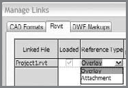
- Displaying nested links in the host file
This is another key feature because you can have two different states: Attach and Overlay. As with AutoCAD's XREFs, if a file has a nested link set to Attachment, when you link it into another one, you will see both files. If the nested link is set to Overlay, it will not show up in other files. This setting is located in the dialog box accessed by choosing File
- Using nested links in the Project Browser
The Project Browser provides the same kind of interaction for links as it does for groups: dragging and dropping will place the link into the view. By right-clicking on the link, you'll get nearly all the options available in the Manage Links dialog box (Reload, Unload, Open, and Reload From).
- Making areas and area boundaries in linked files visible and schedulable
Since Revit Architecture 2009, you can now show areas from linked files, and this includes the ability to create color fill plans that color linked rooms or areas.
- Dimensioning and establishing constraints
You can align and dimension to elements in linked files.
- Copying and pasting elements
By Tab-selecting an element embedded in a link file, you can copy it to the clipboard and paste it into the host file.
- Controlling and changing visibility properties
You can turn categories of linked files on and off, giving you total flexibility in controlling the display of information.
- Binding a Revit link within the parent model
This option creates a group inside the parent file, fully integrated to the project. You'll learn more about binding later in the chapter.
The linked model will display levels, grids, and any annotations they have because the default visibility is defined by the model's visibility. In an elevation, you will see not only the model's levels, but also the linked levels, which may become a problem. To solve this, apply custom visibility settings that override the link in the view. In the Visibility/Graphic Overrides dialog box, choose the Revit Links tab, and override visibility by selecting the Custom radio button. You can control the visibility of all categories in a linked file by using this custom setting, giving you practically unlimited flexibility for what you can display.
This allows you to turn off visibility of categories in the link file. To hide levels, choose the Annotations tab and turn Levels off, as shown in Figure 20.33.

So, is it better to use links or groups to handle repetitive content? Or is there a way to capture the advantages of both groups and links without their disadvantages?
The answer depends on the project and definitely on the workflow. How much interactivity do you need between the elements in the link and the ones in the project? For smaller projects, where file size and performance are not an issue, groups should work fine. If you have a huge project with many instances of repeating elements, linking will reduce file size and make working on the model faster. But if you need control over rooms and cleanups, groups are a better solution.
Had we worked with links for the room units in the previous example, the rooms' file size would not have been a major issue since we are working with instances of a link whose information (and file size) resides outside the project file. If you have a massive repetition of something modular, you might want to consider using links over groups.
If you do go with links but later change your mind, no problem: it is possible to convert the link into a group by binding the link, which transforms it into a group and thus adds it to the project. An example would be linking an entire floor plate full of hundreds of rooms.
In our example, we could have linked the furniture since there is not much interaction with anything else in the project. Because models of furniture can increase the file size, this approach could be a smart way of managing size. We can start working with the furniture as simple components in the floor plan and, as soon as we have something, group and afterward link them. As soon as we have the link, we can just copy it around the whole floor plan, resulting in a marginal file size (we don't have 100 beds, but one bed repeated in 100 instances). Keep in mind that there is no way of excluding objects from the link without affecting the rest.
If you need to work with the group as a link to reduce file size during the project, you can link it (thus losing wall cleanups) and then later bind it back for final construction documentation. When you bind the link, a dialog box will open, as shown in Figure 20.34.

Be careful: as stated in the lower panel of the dialog box, if you bind levels and grids, Revit will create additional uniquely named levels and grids in the project, duplicating information and possibly causing problems.
All in all, binding links is a smart workflow that allows working with a sensible file size while restoring the lost relationships within the project as soon as you bind. Depending on the workflow and the size of the project, this seems to be the best of both worlds. Just remember that while the file is linked, you lose many key benefits of using a fully integrated building information model.
Now that you've gained an understanding of the basic differences between groups and links, there are still some important things to be aware of. We are not trying to sell you on using one or the other, but rather to help you take full advantage of both tools' potential to solve specific problems. Ultimately, your project's criteria should dictate your direction.
The relationship between groups and links is intended to improve workflows. Here are some examples:
When you're looking for a tool that maintains consistency throughout the project and enables the management of repetitive content, when file size is not an issue and interactivity with the rest of the model is crucial, groups are the way to go. (Remember, you can at any point swap the group into a link and vice versa.)
When you are looking for a tool that lets you work with a massive repetition of elements that have little or no interactivity within the project and you want to keep file size down and still be able to schedule the project's contents, think about using links. From a project management standpoint, you could even have someone else on the team work on that information and eventually bind it all into the model, thereby taking advantage of how groups interact with the model.
If you want to keep elements as links but still need rooms, you could use room separator lines as a workaround so you will be able to define rooms without binding all the information into the project. This requires some manual work, but it can be a practical solution if you give some intelligence to the separators. Using the Pick Lines tool when drawing room separation lines gives you a chance to lock the line to model elements and thus capture design intent and keep elements connected.
- Work with repetitive elements.
Many projects have repetitive elements and can benefit by using groups and links efficiently.
- Master It
Think of a scenario in your own practice where elements repeat and how you might use Revit groups to solve the problem.
- Understand the use of groups.
Groups are a powerful design tool. Anyone working with repetitive elements needs to understand how they work.
- Master It
Describe a fundamental benefit of using groups.
- Understand the principles of links.
Links are Revit's second major tool for repetitive elements, avoiding the file size and performance issues associated with groups.
- Master It
Using a link paradigm means that the BIM model now depends on links to external files. Even so, the links can be scheduled, dimensioned to, and graphically altered. Despite that, there are still some limitations. What are they?
- Decide whether to use groups, links, or both.
Knowing when to link a file can improve file performance and provides an easy way to operate on large clusters of building data. You can hide links, remove them, and work on them independently. Knowing when to use groups can help replicate repeated elements quickly. Knowing how and when to use both groups and links helps speed the documentation process.
- Master It
Know that links can reduce the overall file size and thus improve performance when working in Revit; imagine a scenario in which you would most certainly want to employ links over groups.