
No set of documents is complete without annotations to describe the drawings. Even when you are working in BIM and have a digital parametric model, you will need to provide annotated documents by adding dimensions, tags, text, and notes to the drawings, thus making communication of the design to the owner, contractor, and design team clearer and more informative.
In this chapter, you'll learn to:
In any set of documents, showing geometry alone isn't sufficient to communicate all the information a builder or fabricator needs in order to construct the building. Annotations assist in clearly describing your model for others to read and understand. Tags, dimensions, text, and keynotes all need to be added to the drawing to cleanly and concisely guide construction or fabrication. Revit provides a rich set of tools for accomplishing these tasks.
Text, dimensions, and tags are placed in the views, in relation to real elements, not on the sheet. This allows you to annotate a view at any point in the process, before or after the final (sheet) document has been created. Figure 19.1 shows a floor plan annotated in a drawing set.

Rooms help define areas and spaces within the Revit model. Even if a room represents the empty space between boundaries of physical elements, it is still considered an element in Revit, similar to a door, window, or wall. Rooms have properties and can be created, moved, deleted, modified, queried, and scheduled like every other element in Revit. Rooms can also be used for energy calculations and are critical to gbXML export. For more information on this feature, see Chapter 18, "Evaluating Your Preliminary Design: Sustainability."
You need bounding elements to define a space in which you can place the room element and thus generate a room that can calculate its area and volume. Bounding elements for rooms include roofs, walls, floors, columns, and room separation lines.
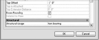
These elements all have an instance property called Room Bounding that determines whether that element participates in calculating room extents. By default, all these elements are set as room bounding. If you do not want an element to affect the calculation of room areas and volumes (for example, toilet partition walls are usually not deducted from the area and should be marked as non-room bounding), select it and clear the Room Bounding option in the Element Properties dialog box (shown checked in Figure 19.2).
Every model element in Revit can be tagged, including rooms. The room tags report information stored in the room element properties. This means you can have the tags report anything about the room based on parameters of the room: name, number, area, finish, and so on. Rooms are separate elements from room tags, which, like all other tags used in Revit, are annotations that can report any information stored in the building elements they are associated with. Door and wall tags, for example, report values of the door or wall elements. Room tags do the same.
In such cases, you can add room tags later in the project, individually for each room or for all rooms that are untagged at once. This means Revit can simultaneously tag any existing rooms in the active view and places the tags in the center of the X formed by the room element. You need to have created the room objects in the project first; then, wherever a room element is found, a room tag is placed in the room. This tool does not create rooms for you if they don't exist.
It's important to note that the tags only report the properties of the room. Deleting the tag does not delete the room element or the information shown in the tag.


The X is a visual aid to show you where room elements already exist within the model. As you can see in Figure 19.3, we are missing a room element in Room 120. To place a room in that space, with the Room tool selected, click in the white area in the middle of the space to place a room element. A blue box appears and a room tag is automatically placed in the room. The Room tool remains active after the placement of each room and allows you to keep placing rooms in sequence. You'll notice that Revit auto-increments each room tag as you place the rooms. If you change a room number, the number of the room you place next is based on the number of the last room you placed.
Once a room is placed, it extends itself to the boundaries of the space in which it is placed and becomes an object in the model. As we mentioned, the room tag is a separate element and can be removed without removing the room element itself or any of the information you might have added to the room element. In fact, deleting the tag from a room will prompt a warning message alerting you that the room element still exists (see Figure 19.4). In a schedule, all these rooms will continue to show up with their proper room names and any other information you've added, regardless of whether they have been tagged.

Once the tag has been removed, you can still select the room element. By default, the room element is not visible within Revit. This is intentionally done to avoid cluttering up precious space within a view. To select a room for further editing or to access its properties, drag the mouse over the space where the room is placed and click when the room element highlights. Click in an area close to one of the crossing diagonal lines to select the room.
Here are some other features critical to rooms that you will want to be aware of as you begin placing them in your model:
Room bounding elements need to create a closed loop. Placing a room in an unenclosed area generates an error message like the one shown in Figure 19.5.

If a room that reports that it is unbounded is not resolved and is left unbounded in the model, it will not properly report in the schedules. There are a few ways to resolve an unbounded room:
If you are still in the midst of design, simply finishing the design may give you the walls or other bounding elements you need to complete the enclosure. Once the room is properly enclosed, the room element will recognize this and dynamically stretch to fill the room
You can delete the room if it has been incorrectly placed. If you decide to remove a room, you must delete the room element itself, not just the room tag
You can use the Room Separation lines tool located in the Home tab, under the Room & Area panel, when expanding the Room tool, which lets you draw a boundary and create room boundaries to define the edges of the space and close the areas where the room leaks
Revit will tolerate a small gap in room boundaries such as walls that don't quite meet or Room Boundary lines that are not quite drawn all the way across a room. In that case, the error message "Small gaps will be ignored by room boundary calculation" will not appear.
Room elements must not overlap. Revit does not accept overlapping rooms and will report an error if this occurs. You may come across this issue in any of three ways:
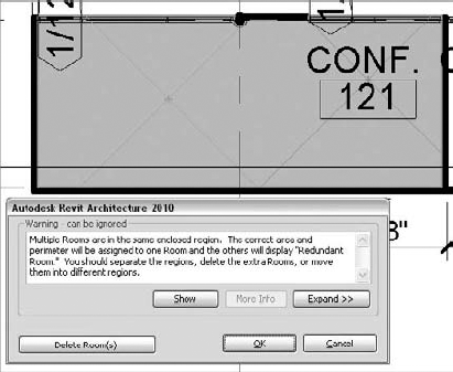
First, you might mistakenly attempt to place a room in a space that already has a room element. If this occurs, Revit will alert you to the issue by showing you both room elements in the space and an error message asking what you'd like to do (see Figure 19.6). Clicking OK in this dialog box will leave both rooms in place. Clicking the Delete Room(s) button will remove the most recently placed room element
The second way this can occur is if you remove a wall or other bounding element between two rooms. Revit will give you the same warning and ask how you would like to resolve the problem (see Figure 19.7)
A third way rooms can overlap is when the height of a room extends into the bounds of another. If a room extends vertically into a room on the next floor, a similar warning message will appear. To view the conflict, you will need to go to section view and check the room extents. It is important to understand that rooms can be volumes with 3D dimensions. Room volumes are covered in more detail in the section "Area and Volume Computations" later in this chapter

So, what happens when you need one room to end and another to begin and you don't have a wall in between? For example, you might want a room to end at the end of a corridor that opens to an entry space, or you may have an open living room and dining room not separated by a wall.
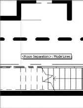
Room separation lines show in plan views as distinctive green lines (see Figure 19.8). You can turn these lines on or off in the Visibility/Graphic Overrides dialog box, or by right-clicking and hiding the category using the context menu.
Room separation lines will print in the plans if you leave them visible. If they are turned off, they will still maintain their room boundaries—but just remember they are there! "Out of sight, out of mind" can cause problems later when you move walls and the rooms seem to react in strange ways; so if you do decide to turn off the visibility of room separation lines, make a note to yourself about it and turn them back on after printing.
Adding a Room Separation Line
In our Foundation project, there was a room named Corridor 127 that needed to be separated into a corridor and an entry area because they had slightly different finishes in the finish schedule. We used Room Separation lines to divide the spaces.
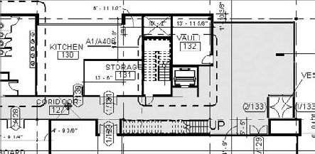
Drawing a room separation line from the stairwell across to the wall created a boundary, allowing a new room to be added named "Entry 139." In the following view, you can see where the room element ends without requiring us to create a wall to divide the space:

You can select rooms in one of two ways: graphically or from a schedule table.
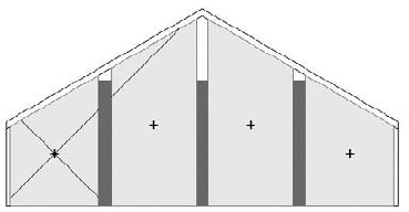
When hovering your cursor over a room object, you will notice that the room object shows up and is represented with its boundary and two diagonal crossing lines, as shown in Figure 19.9.
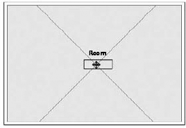
The two diagonal lines might seem strange at first, but they are useful for selecting rooms. Without them, the room element could be selected only at its boundaries—but as those are coincident with many other elements (walls, floors, windows, etc.) the selection is quite tedious. The diagonal lines highlight when the cursor moves over them, so you can select the room (see Figure 19.10). These lines are a subcategory of the room element, and if you wish to see them all the time in the view and not just when hovering over them with the mouse or upon selection, you can turn on the Reference subcategory using the Visibility/Graphic Overrides dialog box. From that point on, all available room elements in your project will be graphically visible. When the Tag on Placement option is checked, your room tag is always placed at the intersection of these two diagonal lines.

Once you've selected a room element, your cursor turns into a move icon and lets you move the entire room somewhere else if needed. When a room is selected and you move it, it automatically takes the extents of the new space. In principle, you are not moving the geometry of the room but you are displacing the room information and assigning it to another space. Moving a room allows you to take all of the data you've entered for the room (wall finishes, ceiling, floors, and so on) and relocate rather than retype it. The same is true for copying a room into a new space.
The graphical room selection can occur in both plan and section views. (Room selection in 3D views is not possible.) You can see, select, change the properties of, and even manipulate the extents of rooms in section views now. When you select a room in section view, two sets of editing grips appear that allow you to manipulate the base and top extents of the room by dragging.
When you select one of the diagonal or boundary lines of a room, you are selecting the room element and can access its properties. When you select the room tag, you are selecting the tag of that room and can access or change the properties of the tag.
There is a difference between using the Move tool when a room is selected and using it when a room tag is selected. When you select a room tag, you are moving the tag around in the room or outside the room: with small spaces, a tag often needs to be taken out of the space the room tag describes because it doesn't fit inside (remember to select the Leader option first). The most common example is a restroom. When you attempt to move the tag outside of the room it is associated with, the tag displays a question mark and you get this warning message:


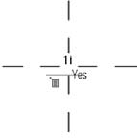
To fix the error and clarify which room the tag is associated with, you can use the Leader option on the Options bar. This connects the room and the tag with a line, and it displays the correct room number and name, which will help you understand the relationship between the tag and the room in the model to which it belongs. Figure 19.11 shows the room tag with the leader line checked.
While you can also tag rooms in a section view, you will not be able to create new room elements in a section view. You can create rooms only in plan views.

Figure 19.11. (A) A room tag doesn't fit well in a small room. (B) Dragging the room tag outside the room it is associated with will turn the tag's content into a question mark (?). (C) The tag leader is activated on the Options bar, so the room tag connects with the room it is associated with and displays its information.
Like all other elements in Revit, rooms have properties. By selecting the room element and clicking the Properties button, you can see the room properties that are available. These properties can be scheduled, displayed in room tags, or used to color-code a floor plan or section with a color fill scheme. The parameters are divided into sections to help organize the information:
- Level
Reports the level on which the room has been placed.
- Upper Limit
Defines the top level of the room. For example, if you have a double-height space (like an open atrium), you might want the upper limit to be more than one floor high so the entire space is treated and scheduled as one element. By default, this is set to be the same as the level on which the room is placed so that you define the actual room height as an offset of Level.
- Limit Offset
Defines the height of the upper limit of the room relative to the Upper Limit setting. This function is critical for volume calculations and gbXML exports. There are some settings that need to be addressed to get accurate results from gbXML exports:
Limit Offset needs to coincide with the bottom of the ceiling plane above for any given room on floors below the roof line
Limit Offset can exceed the top of the roof for rooms that are on the uppermost floor
Rooms cannot overlap vertically for accurate gbXML exports. This means the upper limit of a room cannot encroach into the bottom of the room above it
- Base Offset
Defines the distance at which the lower boundary of the room is calculated, measuring from the base level that itself is defined by the Level parameter. A positive value of the offset sets it above the base level, a negative below. Zero value is set by default and equals the base level.
- Area, Perimeter, Unbounded Height, and Volume
These are noneditable fields that report the metrics of the room element. We will review how these numbers are calculated in the next section.
- Identity Data
This section includes identity information about the room. You can manually add data using these parameters and it will show up in tags. If you're using a color fill scheme, it will also be used to color-code the plan.
- Phase
This is a noneditable field that reports the phase in which the room was created. Remember that once you place a room you cannot change the room's Phase property (unlike geometric elements). If you need to move the room to another phase, you'll have to re-create it in that phase.
You can set different rules that dictate the automated calculations of area and volume for room elements. The selection of available rules can be found in the expanded panel of the Room & Area panel on the Home tab, by clicking on Area and Volume Computations. The resulting dialog box, shown in Figure 19.12, gives you the option to select from a number of area calculation schemes by relocating the boundary element of the rooms.
It is important to note the difference between room areas and area plans. Area plans follow different rules and treat exterior and interior walls differently. The Area Plans tool places areas automatically in the model, once the Area Plans function is initiated. Room elements have to be manually added in each space within the plan or design, and the rules that are set to define them apply to all the walls.

When calculating room area and volumes, you can choose among the following boundary locations, resulting in different calculations:
In addition to calculating room areas, Revit can calculate room volumes. This feature is not enabled by default since volume computation can negatively affect the overall performance of Revit. You can decide at any time to activate the volume computation. This option is available in the Area and Volume Computations dialog box by checking the Areas and Volumes option in the Volume Computation group. We recommend enabling this option only when you need to create or print schedules or other views in which volume computation needs to be visible (such as gbXML exports). How much the volume computation affects the performance depends on the size and complexity of your model and your processor speed, but the general rule is to follow our earlier advice and activate it only when needed.
Here are some rules that you should be aware of when activating room calculations:
Every room can have an independent theoretical room height that you define using the Limit Offset room property. This is the height used for calculating room volume if the actual height of the ceiling, floor, or roof above it is higher than the applied height of the room (see Figure 19.13)
If the room height is greater than the height of the existing ceiling, floor, or roof, then the height to the first architectural element the room object hits is used to calculate the volume of the room (see Figure 19.14)


Note that the room height can begin to cause other problems if it extends into the room on a floor above or below, even if the room element does intersect an architectural element, as noted previously (see Figure 19.15).
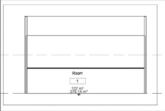
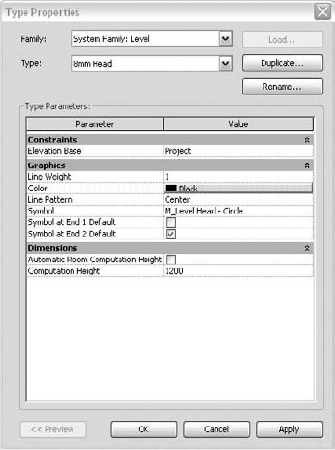
Figure 19.15. A change in the room height doesn't have any effect on the room volume calculation unless it hits the floor or ceiling above or below. (A) Computational height is set to the standard 1200mm. Parts of the volume are missing in the calculation. (B) Change the computational height to floor level for the correct computation.
Usually a room height is set to 8′ (3m); so, depending on the default floor-to-ceiling height, it will often not be the real height of the room. You can verify that easily in section, when hovering over and selecting the room element. Adjusting the room height to the actual height of the space is easy in Revit 2010: you can graphically pick the room limits in section and adjust the height, as shown in Figure 19.16.

Figure 19.16. Arrow grips at the base and top limits of a room element allow you to graphically manipulate the height of a room. (A) Default room height; (B) adjusted room height.
Revit Architecture uses the perimeter of the room at the computation height when computing the room area and volume. The computation height is a type property of the Level family and can be changed any time. By default, it is set to 4′−0″ (1200mm).
You can see the computation height graphically when you select a room element in section: it is represented with a dotted line across the lower part of the room (Figure 19.17).
To view or change the computation height, select a level line in section or elevation view and access its type properties, as shown in Figure 19.17.
For buildings with vertical walls, the room computation is straightforward, as explained earlier. However, if a building includes sloped walls, you may need to adjust the computation height to achieve more accurate room areas and volumes.
The typical case would be when working with rooms that are bound by nonvertical walls. Having the perimeter calculated at a height of 4′ (1.2m) would result in omitting portions of the floor area. To fix this, you have to adjust the computation height to be close to the floor plane.
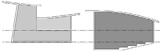
Changing the computation height instantly affects the room perimeter and allows more accurate computation of rooms with variable width. An example of the calculation of the room area and volume is shown in Figure 19.18.

Figure 19.18. Changing the computation height allows for more accurate computation of rooms with variable width. (A) Computational height is set to the standard 1200mm. Parts of the volume are missing in the calculation. (B) A change of the computational height to floor level allows for the correct computation.
In general, Revit 2010 has brought some improvements in the calculation of volumes: the computations are now more flexible in adjusting to nonorthogonal room sizes and volumes (Figure 19.19). Revit 2010 can correctly calculate rooms with nonhorizontal top limits. The room element adjusts its shape to the shape of the space it calculates.
When the volume calculation is off, the room in section appears as if it doesn't recognize the room boundaries (Figure 19.20A); when the room volumes are activated, the room shape adjusts to fit the shape of the space (Figure 19.20B).

If room bounding elements narrow as they rise, Revit calculates volume properly (Figure 19.21). If, however, bounding elements slope in a way that makes the room widen toward the upper limit, Revit ignores the side spaces when calculating the volume (Figure 19.22).

Figure 19.21. Section view of a room: If room bounding elements narrow as they rise, Revit calculates volume properly.
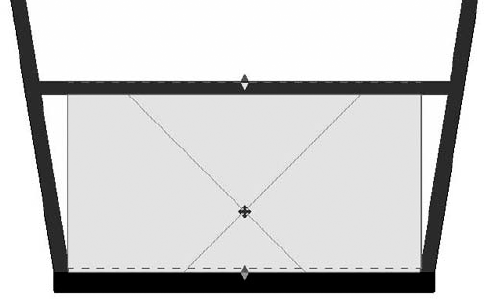
Figure 19.22. Section view of a room: If room bounding elements widen as they rise, Revit calculates volume incorrectly.
Finally, if a room-bounding element does not reach the upper boundary of the room, the space above the element may not be included in the room volume (Figure 19.23).
Once you populate your model with rooms and begin adding information to each room about its department and finishes, you'll most likely discover that information about rooms tends to repeat. Representing this information will be useful when you're generating room and finish schedules. In previous chapters, we discussed ways to report the information in those elements using the schedule functionality. But what if you want to define a common set of parameter values that can be shared across many rooms? For instance, if you are working on a large office project, doing a room finish schedule that lists individual rooms might be unnecessary if many of the rooms share identical finishes. For these situations, a specialized schedule called a schedule key can save time. Schedule keys can report any number of values that repeat across similar elements.
Imagine the time it would take if you had to manually enter all your finishes in each schedule in each project! Schedule keys are a big time-saver and ensure consistency.
Since we have already added rooms to the Foundation model, let's make a room finish schedule using a schedule key for the project. To do this, we need to generate two schedules. The first one defines the room styles by using what is called a key name. The second schedule links our room styles to the rooms themselves.
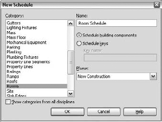
Let's begin with the room style schedule. On the View tab, choose Schedule
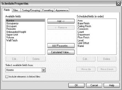
Choose Rooms from the list on the left, select the Schedule Keys radio button (see Figure 19.24), and click OK.

The next dialog box should look familiar (Figure 19.25). It is basically identical to the Schedule Properties dialog box (in fact, it has the same name), but one tab is not included in the dialog box: the Filter tab.
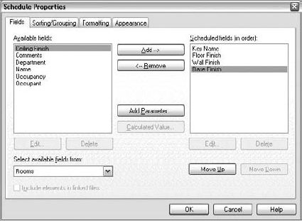
When you select the Fields tab, you will notice that one of the values is already on the right side to be included in our schedule: Key Name. Now you want to move the following values from the left to the right (they've already been moved in Figure 19.25):
Floor Finish
Wall Finish
Base Finish
The remaining tabs in this dialog box are identical to the dialog box for other schedule types. For more information on formatting or changing the appearance of a standard schedule, see Chapter 17, "Fine-Tuning Your Preliminary Design." Once you have these values selected, click OK. A blank schedule like this one appears and is available for you to fill in with finish values:

Click the New button on the Modify Schedule/Quantities context menu to begin to add standard room finishes to the schedule. In this table, the key name is important because it will be the link between the two schedules. Using the New button, add the following room styles to your table: Key Name, Floor Finish, Wall Finish, and Base Finish.

Once the schedule is complete (you can always add to it or modify it later), you need to create the finish schedule to be used in the construction document sheets. Again, select Schedule/Quantities from the View tab and select Rooms from the list. This time, leave the default value Schedule Building Components selected (Figure 19.26) and click OK.
Again, you'll see the standard Schedule Properties dialog box. Add the following fields to the Schedule fields list (the right side) in this order and click OK:
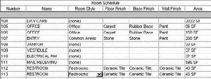
The schedule that shows up will be a list of the rooms in the project, sorted by room number with (none) set as the value for Room Style. The Floor, Base, and Wall Finish columns will all be blank. Some sample lines are shown in Figure 19.27.

From here, adding values and finishes to the rooms by room style is fairly easy. Once you select the (none) value in the Room Style column, you will be given the option to select from the drop-down list of values we defined in the room style table (Figure 19.28).

Selecting a value from this list automatically fills in the values for the Floor Finish, Base Finish, and Wall Finish columns to match the values we defined in the previous schedule. As you modify values in the room style schedule, they are dynamically updated in this schedule, adding consistency and predictability to your workflow (Figure 19.29).
Tags are text labels for elements such as doors, walls, windows, rooms, and a host of other objects that architects typically need to reference in a set of drawings. In Revit, tags are intelligent, bidirectional symbols that report information stored in the properties of an element. A value can be directly edited from the tag; likewise, editing an element's properties affects the tag.
A wall tag, for example (Figure 19.30), can display the wall type that is set in the properties of the wall itself, but it can show much more information, such as the wall's fire rating or area.
Revit comes with a variety of tags that can be customized to meet your office's graphic standards or needs. The preloaded tags in the default templates cover many common requirements but are by no means exhaustive.
Every category of a family can be tagged, and you can load multiple types of tags for each category. Tags are loaded like any other family or component in Revit. From the Insert tab, select the Load Family button, Load Family, and browse to the tag you want to add to the project.
If you have designed some tags that you use frequently in your project, you should load them in your office template.
Tags can be automatically placed during the creation of an element (using the Options bar setting Tag on Placement) or can be placed later. You can insert tags by clicking the Tag button on the Annotate tab (see Figure 19.31).

During tag placement, the Options bar lets you position a tag in several ways.
When tagging elements, if you don't have the appropriate tag for the element you're trying to tag, click the Tag button. In the resulting dialog box, you can load additional tags without having to cancel the command and go back to the Load Families tool. If you click the Tag button but don't have a tag of that category loaded for the element you want to tag, you'll be prompted to load one.
Tags can have a horizontal or vertical orientation and can include or omit a leader line. In the case of a wall tag, you typically have a leader coming from the wall, whereas you probably would not use a leader with a door or window tag.
Clicking the Tag button offers three tagging options:
- By Category
This option allows you to tag elements in the model by category or type. Examples are doors, walls, windows, and other commonly tagged elements. After you choose By Category, the elements you can tag highlight as you hover your mouse over them in your view. Revit also displays a ghost image of the tag you're inserting and the value in that tag.
- Multi-Category
Use the Multi-Category tag when you want to tag an element across different family types—for instance, when you're using a similar glazing type in your windows and exterior doors and you want to be able to tag the glazing consistently. The Multi-Category tag allows you to have the same tag and tag value for the glazing in both families. (Fire rating is another common application of this tag.)
- Material
The Material tag lets you tag the materials in a given family. Tagging a wall by material exposes materials used in the wall assembly. This allows you, for example, to tag the gypsum board, sheathing, and studs separately.
There are two ways to modify text in a tag. Selecting the tag makes the text an active control and turns it blue; just click the blue text and start typing. This changes the value directly in the tag. The second option is to alter the properties of the element being tagged. Using a wall example again, if you select the wall, navigate to its properties, and change the Type Mark field, the wall tag updates to reflect this change. See Figure 19.32 for examples of each location.
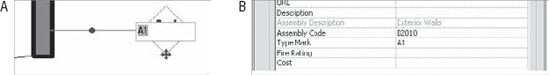
Figure 19.32. Changing a tag value can happen by changing the value directly in the tag (A) or by changing the Type Mark field in the element's properties (B).
Whichever way you choose, you change the symbol text for every instance of that tag type. Therefore, if you change a wall type from A1 to A2, you change every instance of that wall family that was previously tagged A1.
Some tags only report instance values—values that are unique to the individual element. A room tag or door tag is a common example. The room tag graphics are consistent, but the room name varies from room to room. Doors are often tagged like this, with a unique value for each door. With these types of tags, Revit detects if you enter duplicate values and warns you when that happens.
You can tag many elements at once using the Tag All tool in the Annotate tab. This time-saving feature lets you tag all the elements in a view simultaneously. When tagging elements, keep in mind that this feature only works with component families and not system families. For example, you cannot use Tag All Not Tagged for walls or floors.
During early phases of design, you often are not concerned with tags and annotations but are more focused on the model. Tags can become graphic clutter that obscure the design at times. Later in the process, when the design is more complete, you may want to annotate the drawing quickly. This is where the Tag All tool can be helpful. When you select this tool, the dialog box shown in Figure 19.33 appears. You can orient your tag or add a leader to it before tagging all the listed elements in your current view.

If you have elements selected, you can choose to tag only these elements. Note that this option is grayed out in the sample dialog box in Figure 19.33 because nothing in the model is selected.
Try the following exercise.
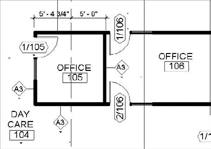
In the Foundation file we have been using, open the view called Level 1. You'll notice in this file we've moved the documents forward a bit by defining the views we'll be using in our callouts. In this view, using the tools mentioned, let's add tags for the doors and walls.
On the Annotate tab, choose Tag By Category. Make sure your leaders are turned off in the Options bar before adding any tags to the plans.
Mouse over the door, and click when it highlights. This will insert a tag for the door centered on the door opening. By choosing Horizontal or Vertical for the tag orientation from the Options bar, you can quickly run through the plan placing door tags.
These tags might not be ideally located. As we've mentioned, the tag will come in centered on the door. However, it is a simple process to drag the tag to a more appropriate location if necessary.
Now that you have placed the door tags, you can see how each door is tagged and change the tags if appropriate. As we mentioned earlier, to change the value for any of the tags, simply select the tag, and then click on the blue text. This will allow you to enter a new value in that field. For our drawing set, you are going to number the doors with a door number/room number system, as shown in Figure 19.34. You can also change these values directly in the door schedule.
Another way to quickly tag the doors in this plan would be to use the Tag All function shown in Figure 19.33. This feature applies all the tags of a given family type at one time within the model. It's a quick way to populate a view with tags.
Using the Tag By Category tool on the Annotate tab again, highlight and select the interior walls. For wall tags, be sure to turn on your leaders, but adjust the leader size in the Options bar to ¼″ rather than ½″. The finished floor plan should look like Figure 19.35.

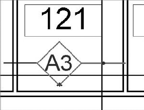
The number of annotations possible in any given view can be rather large, so it's typically a good idea to conserve the available white space on the sheet by not duplicating notes and tags. As Revit is designed to annotate only single items, avoiding duplication in a given view can be a challenge using only the standard tools. In Figure 19.27, you'll notice that in Room 121, the wall tag A3 has a leader going left and right to each wall. The leader on the left is a drafting line (see Figure 19.36). While this eliminates the parametric value for that single wall condition, in many cases adjacent interior walls have the same type. Before you adopt this approach in a project, you should weigh your need for accuracy against workflow considerations and how much space is available in your documents for this kind of approach.
Each Revit element has a set of parameters defined by default, such as material, length, area, or other characteristics that describe the element. Often, however, you need additional parameters to describe an element that you don't find in the standard parameter set. For such purposes, Revit lets you add your own parameters to elements and schedule or tag those parameters. There are a couple of ways to add these custom parameters that offer additional information about the element, depending on how you want to leverage them in the further development of the project and where you want them to be visible:
If all you intend to do with your custom parameter is to schedule it (for example, a parameter called Lockable that describes whether or not a door has a lock), you can take two approaches:
Add that parameter directly in a schedule using the Add Parameter function. This adds that new parameter only to the element that you create the schedule for, such as the door element
Create a new project parameter that you will be able to assign to one or more element categories—the difference is that this method allows you to assign the same custom parameter to more than one element (doors and windows, for example)
If you wish to be able to both schedule and tag your custom parameter, meaning that you wish to see the value of that parameter being called out by the element tag, you will need to use shared parameters. As the name indicates, shared parameters in Revit are parameters that can be shared between families and projects. This will allow you to add information to your elements that can be both scheduled and tagged in your project. An example of this might be a custom parameter for a room. It indicates whether the room is public or private, or heated or not heated. To see that information in the room tag, you would make this a shared parameter
Later in this chapter we will use a detailed example to present the whole process of creating and using a shared parameter. First, however, we present a basic procedure for creating a custom parameter that doesn't need to be shared.
You can create a custom project parameter at any time in the project cycle. You can then assign it to any one or more element categories and generate schedules that will be able to call it out.
In the following example, we want to track whether or not the materials used in the project are recyclable, so we will create a new custom parameter recyclable, which doesn't yet exist in Revit as a standard parameter. We will assign it to the Materials category.
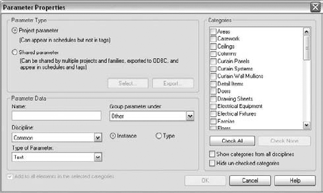
To add a new project parameter, select the Manage tab and from the Project Settings panel select Project Parameters. In the resulting dialog box, click the Add button (see Figure 19.37).
In the next dialog box, give the new parameter a few definitions (see Figure 19.38):
Name, used for describing the parameter
The group the parameter will belong to. This is specifically for sorting the parameter in the Element Properties dialog box
The discipline. This is also used as a method to help organize the parameters
Whether it is an instance or a type parameter
Instance parameters are specific to any instance or insertion. So if you insert three doors, they can each have different instance parameters. An example might be the door number.
Type parameters remain consistent for the family type. So, in the door example, this might be the door width, and you'd create a separate type for each door style (36″, 34″, 32″, etc.) within the project.
What type it will be (text, integer, yes/no)
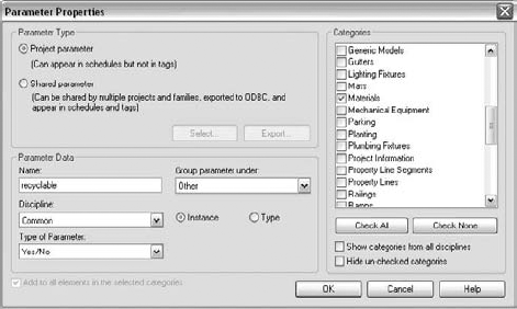
Following a scenario in which we are adding a recyclable parameter to the materials, name the parameter recyclable and assign it to the category Materials. Make it an instance parameter of the Yes/No type (see Figure 19.39).
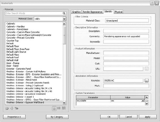
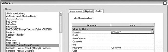
Navigate to the Materials dialog box (by clicking Materials on the Manage tab) and select the Identity tab. You will find the parameter you just created (see Figure 19.40).

With these steps, you have just assigned the new Recyclable parameter to all materials used in the project. What is left to do is to define their state for each material (Yes or No). To do this, you can choose Materials on the Manage tab and, for each used material, set the value of the recyclable parameter on the Identity tab.
Once you do, you can create a material takeoff schedule (on the View tab, select Schedule/Quantities
Note that you cannot tag the parameter you just created and will not be able to make it appear in the material tag. The reason for that is simple: the existing material tag will not recognize a custom parameter that you create on the fly in a project as it has no label that can call it out attached to it. Tagging a project parameter is only possible using shared parameters. They are used both on the elements and in the tags, and thus the tag understands them and can call them out.
When you want to schedule and tag a custom parameter you have created, use shared parameters. For example, you might wish the hardware set information of a door or window to appear in the door or window tag, or the level of radioactivity of medical equipment to appear in the equipment tag, or the door tag to display whether or not a door has a lock. None of these parameters exist by default in any of the families, so you will need to create them and add them to the families if you want to use them. They also don't exist in any of the family tags, so to be able to call out the information of these customer parameters in the family tags, you will need to add the same parameters to the tag families as well. The concept seems complicated, but it's actually straightforward. Imagine this: you have a set of chairs, some that are original Thonet chairs and some that are reproductions. You want to tag the originals with a special parameter called original. To do this, you must add that parameter in the tag (by creating a label and calling it out), and you then have to add the parameter to the chairs that are the originals. Now, if you created the original parameter as a project parameter, that parameter would only exist in the project you created. Neither the chair family nor the tag family would be aware of it, as they were created prior to the creation of the parameter and didn't have it among their parameters. That is where shared parameters come in handy—they allow you to reference the same parameter between project and family.
Let's look at the workflow behind creating these, using the example of a hardware set for doors and windows. We will do an exercise in which you will create a door custom parameter called hardware that is schedulable and taggable.
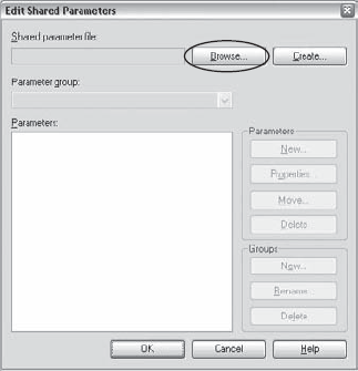
Create a new shared parameter file. At this stage, it doesn't matter if you are in a Revit project or in the Family Editor. In both environments, you can choose the Manage tab and click Shared Parameters. This opens the Edit Shared Parameters dialog box.
Select the Create option and enter a shared parameter file directory path and name. This is where you will store all your custom-created shared parameters. Make sure that the folder you store your shared parameters in is saved somewhere accessible to the rest of your team.
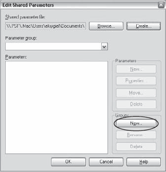
Next, create a group by clicking the New button in the Groups cluster of buttons that is now activated. This might be confusing, but in principle every shared parameter belongs to a group as a higher instance in a hierarchy, so you have to create at least one. If you use lot of shared parameters, the groups can come in handy for locating parameters. So, create a group and name it Hardware.
Once you have created the group, you can create the shared parameter by clicking the New button. Name the new parameter Hardware Set. This is the shared parameter that we wish to have visible in our schedules—and more important, that we wish to tag.
The shared parameter you've just created is nothing more than a simple text (.txt) file that you will find in the directory you created at the beginning of the exercise. You can now assign this parameter to any one of the following:
The tag family
The project (as a project parameter)
The categories of elements you wish to have that parameter
For this exercise, use the file located in the Chapter 19 folder on the book's companion web page (www.sybex.com/go/masteringrevit2010) to create a shared parameter file.
In the following steps, we will first create the shared parameter file:
In the Edit Shared Parameters dialog box, click Create (Figure 19.41).
Specify the directory path and name of the new file; then click Save. The name of the new file that you assign here is not as important as the fact that this file needs to be accessible in Read mode for all team members. Do not give the filename an extension because the
.txtextension will be appended automatically.
Revit requires that you create a group before you can create a shared parameter.
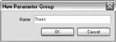
In the Edit Shared Parameters dialog box, under Groups, click New to create a new parameter group (Figure 19.42).
Give the new group the name Doors. To help you organize your shared parameters, you will want to name the group logically.
Now that you've created the backbone for the shared parameters, let's create the parameters themselves.
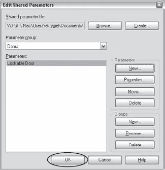
Still in the Edit Shared Parameters dialog box, click the New button in the Parameters section (Figure 19.43).
In the Parameter Properties dialog box, do the following:
Enter a name for the new shared parameter. Call it Lockable Door
Under Discipline, keep the default, Common
In the drop-down list under Type of Parameter, select Yes/No
Confirm by clicking OK


And that's it! You've just created the shared parameter for door hardware and are ready for the next step: adding it to a door tag in the Family Editor, then moving into the project environment and assigning it to the Doors category. As explained earlier, you can only tag a custom property that you define if you share it across the families and the project.
In the following steps, we'll make our shared parameter a project parameter and assign it to the Door category.
Open the file
Foundation.rvt.Open the plan view Level 1.
Choose the Manage tab and click Project Parameters. A list of parameters will appear. The Lockable Door shared parameter that you just created is not among them, so you will need to click the Add button (see Figure 19.44).
In the Parameter Properties dialog box, in the Parameter Type group you will see a Shared Parameter option. Check it and click Select.

The Edit Shared Parameters dialog box opens, and you will see the shared parameter you have just created, automatically selected. Click OK (see Figure 19.45).
In the Parameter Properties dialog box, set the Group parameter to Identity Data. Make sure you select the Instance radio button. This will make the parameter instance based since in the real world the same door type may or may not be lockable.

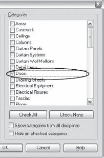
All that is left to do now is select the category to which this shared parameter will apply. In the Categories list, select Doors (see Figure 19.46). Note that you can assign the parameter to as many categories as you wish.
Confirm all that you have done by clicking OK.

Now that you've created a shared parameter, you need to add the tags to show the lockable and nonlockable doors.
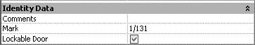
In plan view, select a door (let's say the door belonging to Room 131—Storage) and open its properties (see Figure 19.47).
Notice that the newly created parameter appears in the group Identity Data, just as we set it to be. Note, however, that the value is gray, meaning that it has not been set.

To set the parameter to one of the states, lockable or not, click the check box. Click again to clear the check box and void the selection.
You don't have to set this parameter one door at a time. You can select multiple doors that will have a lock and check the box using the same method or set this value through the door schedule itself.
If you only wanted to add a new parameter to the door category and schedule it, you could have done so by using a simple project parameter. The point of making a shared parameter is that you will be able to add it to the door tag family as well as tag the door and display the value of the shared parameter in that tag. You will now add this shared parameter to the door tag family so that the tag understands the shared parameter value and displays it. If you just added a new label for the shared parameter and the door is lockable, the door tag for a lockable door would simply display "Yes." The parameter we made only reports Yes/No values, which is not very helpful. So you'll need to add a static textnote next to the label: Lock (see Figure 19.48).

There are two ways to create a tag that calls out a shared parameter:
Take an existing door tag, duplicate it, and then add the shared parameter to the duplicate
Make a tag from scratch
In this exercise, we will make a new door tag from scratch.
Go to the Application Menu,

In the New dialog box, select the family template
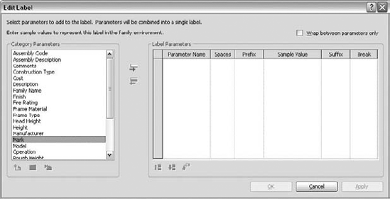
Door Tag.rftand click Open.The Family Editor opens in plan view, showing two crossing reference planes. The intersection of the two reference planes represents the insertion point (and center point) of the tag to be created. In the tag, you'd like the following information to be displayed: the door mark and whether it has a lock.
Click the Label button on the Create tab. Click with the mouse somewhere close to the crossing point of the two references.
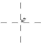
In the Select Parameter dialog box, select Mark and click OK (see Figure 19.49).
The Mark text is set to ⅛″ (3mm) by default. This might be a bit big if we want to add a mark and a lockable parameter, so we need to make the font size smaller. In the Element Properties dialog box of the mark, click Edit/New. Click Rename in the Type Properties dialog box and enter a new name, indicating the size of the mark, 3/32″ (1.5mm bold). Click OK.

In the Type Properties dialog box, set the properties of the mark as shown here:
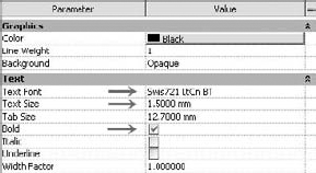
Confirm by clicking OK in the remaining dialog boxes when finished. What you see should be similar to what is shown here:
Note that
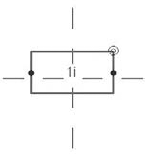
1iis just a symbolic representation of the label. Once placed in the project environment, it will read and display the mark of the door.Remember, the goal was to display the hardware information about the door within the door tag. For that, we will now add the shared parameter Lockable Door to the door tag. Click again on Label on the Create tab and position this second label below the first, also centered in the tag.

In the Edit Label dialog box, click the Add a Parameter button, and then in the Parameter Properties dialog box, click Select. The shared parameter list opens; here you will find the Lockable Door parameter. Select it and click OK in all remaining open dialog boxes.
You can also select the Shared Parameter label in the Drawing area, click Modify to access its element properties, and set Sample Text to Yes.

You will probably want to change the size of the text here as well to 3/32″ (1.5mm), so navigate to Edit/New and under Type Properties, select Duplicate. In the Name dialog box, enter 3/32″ (1.5mm). Confirm by clicking OK.

Clear the Bold parameter and click OK in all remaining dialog boxes.
Adjust the position or the size of the label if needed.

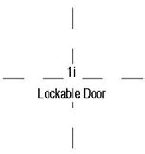
All that remains for you to do is to add the fixed text that will say "Lock:" and position it just in the front of the shared parameter label.
Click Text in the property dialog box. In the drawing area, click somewhere in front of the label Yes.
Enter the text Lock: and on the Options bar, select Properties. Repeat Steps 6 and 7 of this exercise to adjust the size and name of the new text type to match the label we added. Click OK in all remaining open dialog boxes.

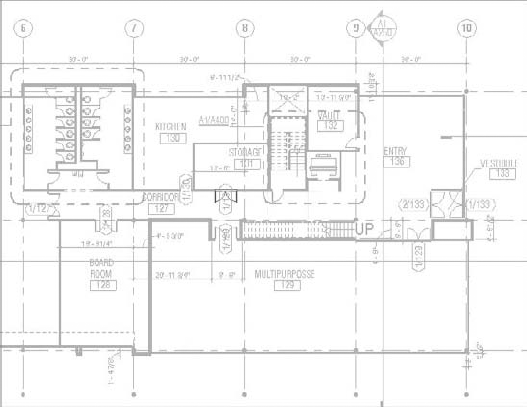
The tag is ready. Save it and load it in the project Foundation.rvt. If you have already placed door tags, you can select them all and exchange them with the new tag that contains the shared parameter by simply selecting it in the Type Selector. You will notice that now all your door tags will display the mark on the top and the word Lock at the bottom. For doors that you previously defined as lockable, it will also show Yes. You will see that many doors have nothing shown in the tag after Lock:. Those are the doors that haven't been marked Yes or No, such as the one in Figure 19.50.

Notes are a critical part of communicating design and construction intent to contractors, subs, and owners. No drawing set would be complete without written definitions and instructions on how to assemble the building. Revit has two primary ways of adding this information to the sheets. One way is through text. Text in Revit consists of words arranged in paragraphs with or without a leader. Text can be used for specialized annotations, sheet notes, legends, and similar applications. Keynotes—the other way of annotating a drawing—are element-specific and can be scheduled and standardized in the Revit project file. Chapter 4, "Setting Up Your Templates and Office Standards," briefly introduced text and keynotes as elements you can include when customizing your template. In the following sections, we'll explore the use and function of both tools in more detail.
Text is easy to add to any view. However, it's important to understand that text is nothing more than a view-specific annotation. Specific text families maintain a parametric relationship throughout the project, and changing one text family type changes each instance of that type throughout the project. While text is a family within Revit, it is not directly tied to values of other families like keynotes or tags. Text is only text, and it will not dynamically report properties from elements it is pointing to.

As with all the elements in Revit, there are ways to change the look and feel of the object being created. Once you've selected the Text tool, the Type Selector and Options bar provide some formatting options:
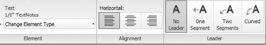
The Type Selector allows you to choose a style for the text you're about to create. You can manage each text style using the Properties dialog box, which lets you modify parameters such as font, size, and color. To create a new text style from an existing one, click the Element Properties button and in the Instance Properties dialog box choose Edit Type and then choose Duplicate to duplicate the type and make adjustments to the properties (see Chapter 4). You can also choose to add a leader to the textnote before placing the note.
There are four options for leaders:
No Leader
One Segment
Two Segments
Curved
Once you've placed the text, selecting the note itself provides additional options. You can add or remove additional leaders and rejustify the placed text. Note that when you are adding or removing leaders, the leaders will be removed in the order they were added to the text.

To edit the text, select the element. The letters will turn from black to blue. You can then click to place your cursor inside the text, and begin editing. When you're editing the text, the Options bar will display formatting controls for bold, italic, and underline text styles. These apply to whatever text you've selected in the note.

When you use the Move command, you move both the text and the leader. When you move text by dragging the arrow icon, you move only the text box, leaving the leader anchored in its original position. When moving text with the arrow icon, Revit will automatically align vertical and horizontal text and leader nodes. This is designed to help you achieve a more consistent graphical appearance. One of the biggest limitations of Revit is that you cannot apply changes in text style to multiple elements (tags, schedules, title blocks, keynotes, or dimensions, for example). So, if you want to make all text in Revit use a particular font, you will not be able to change a global project setting. Instead, you will need to edit each element's type individually. A good way to avoid this type of change is to standardize the fonts in your project templates, as covered in Chapter 4.
Keynotes and textnotes are written annotations that use an external file to relate text to specific elements in the model. You can format font style, size, and justification in the same manner you can format standard text, but keynotes and textnotes behave similarly to a Revit family. This means you can insert different family types of text in Revit, just as you would door or window families. Changing one instance of the family type changes all the instances in the project. Because keynotes and textnotes act as families in Revit, they can also be scheduled.
What's the difference between a keynote and a textnote? A keynote is a short reference, typically a number followed by a couple of letters. An example would be 03300.AA, which points to a cast-in-place concrete wall. The 03300 portion of the note refers to the specification section the note is generated from, and the AA portion is a sorting mechanism used to differentiate cast-in-place concrete from another note in Division 3 of the specifications.
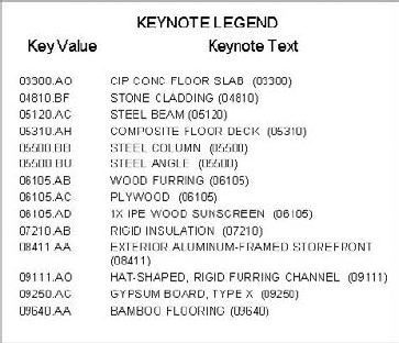
All of the notes on a given sheet are keyed back to a legend, which is typically placed on the right side of a sheet. This reference helps you add more detail and understanding to the keynote without having to reference the specifications directly. (See Figure 19.55 later in this section for an example of a keynote and legend.)
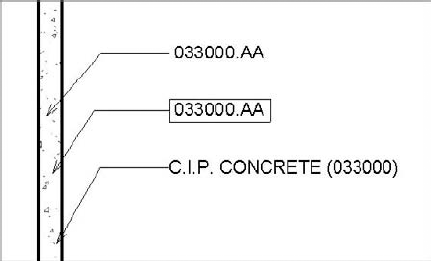
Textnotes are very similar to keynotes, but they combine a short description of text and the key into one note. This saves you from having to coordinate the legend on the sheet and puts the note right next to the item you are pointing to. (See Figure 19.52, later in this section, for an example of textnotes.) No matter which style you prefer, you can create both the keynote and textnote with the same command in Revit. Since the command is called Keynote in Revit, we will refer to the process from here on out as keynoting regardless of the style of keynote (or textnote) you choose to use. See Figure 19.51.
The Keynote command is located on the Annotate tab. When you add keynotes in Revit, you have three options:

- Element
This option allows you to note an element in the model, such as a wall or a floor. This type of note is typically used if you want to note an entire assembly, such as a wall assembly. You can find this value in the family properties of that element.
- Material
This option allows you to note a specific material in Revit. You can add a note to concrete, gypsum board, or insulation, even if they are a part of an assembly.
- User
This option allows you to select any model-based component in Revit and define a custom keynote for it. Notes defined this way differ from those defined as element or material because they're unique to the particular object selected. They can be used in conjunction with element and material notes.
All of these note types can be used in conjunction with one another. Using an element note to add a keynote to a wall doesn't mean you can't also use a material note to call out the individual materials in the wall assembly.
A core concept in keynoting is how the notes react in the model. Keynotes are integrated into Revit just like any model element. Keynoting an object in Revit lets you associate a text value with that family's keynote parameter. This value is consistent for every identical element in the model. For example, all doors have a type parameter that lets you set the keynote value. If you keynote a door—anywhere in the model—the keynote will show that value. Likewise, if you ever change the value of the keynote for the door type, all keynotes for that door type will update automatically.
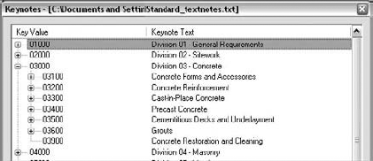
Keynotes are special in that you cannot edit the text of a keynote directly in Revit. All the keynotes in Revit are tied to an external text file, and can only be edited in this location. This file can be modified at any point to add or remove values and notes. A sample list looks like this:
03100 | Concrete Forms and Accessories | 03000 |
03200 | Concrete Reinforcement | 03000 |
03300 | Cast-in-Place Concrete | 03000 |
03400 | Precast Concrete | 03000 |
03500 | Cementitious Decks and Underlayment | 03000 |
This external text file is designed to keep annotations consistent by storing all of them in one repository. Every time you add or change the text of an annotation and reload the text file, it dynamically updates all the keynotes of that type used in the project.
You can edit a keynote text file (.txt) or add one to a project at any time. You can have multiple text files for various projects, but you can have only one text file per project at a time. The text file works just like any other Revit family. Since all the notes are parametric, changing a note in the text file will change all of the notes in the project when the text file is updated.
A powerful way to ensure consistent use of notes throughout your office is to create a master text file for your various project types. These master note lists can be linked to materials or assemblies within your project template so that you can immediately begin inserting common notes into any project. To link keynotes to a material, click the Materials button on the Manage tab and select the Identity tab. In the Keynote field, a predefined note can be selected from the master list and added to any material. The same is true for any assembly. Simply choose the assembly's properties (such as a wall or floor) and select the keynote field to enter a note value.
Since the keynote text file is separate from the Revit file, if you send a project file to someone and don't send keynote.txt, that person will be able to see all the keynotes you've added to the views but won't be able to add or edit the notes without the text file.
The default Keynote text file in Revit is found in C:Documents and SettingsAll UsersApplication DataAutodeskRAC 2010Imperial Library (or Metric Library) and is called RevitKeynotesImperial.txt or RevitkeynotesMetric.txt.
To edit this file, open it in Notepad or Excel and follow the format already established in the file. Let's look at that format to get a better understanding of how to customize keynotes.
The first few rows designate the groupings. They consist of a label (in this case, a number) followed by a tab and then a description. An example grouping looks like this:
03000 | Division 03 - Concrete |
Below the groupings, with no empty lines in the file, are the contents of the groupings. These are shown with a minor heading, a tab, a description, a tab, and the original grouping header. Here's an example:
03200 | Concrete Reinforcement | 03000 |
Here, 03200 is the subheading, Concrete Reinforcement is the description, and it all falls under the 03000 grouping from the previous example.
Using this method, you can add or edit notes and groups of notes to the keynote file. It might seem horribly inefficient at the beginning of the process to have to constantly go to the keynote text file to edit or add notes. While this might seem like a burden, it can be a blessing as well. Accessing this file ensures a global consistency within the keynotes on a project that is unattainable in most drafting applications. If you are feeling frustrated with having to access this file to make changes, think about all of the time you are saving not having to check your set sheet by sheet to verify that all of the notes pointing to a material are the same.
Once you change a keynote text file, you need to reload the file into Revit to update the keynotes. You can open the dialog box to change or update the text file by choosing the Annotate tab, expand the Tag panel, and choosing Keynote Settings (Figure 19.52).

In the Keynote Table group, you define the path to the text file used for keynoting:
- Path Type
Path Type defines how Revit looks for your text file using one of three methods:
- Absolute
This option follows the UNC naming conventions and navigates across your network or workstation for a specified location.
- Relative
This option locates the text file relative to the Revit project file. If you move the Revit file and the text file and maintain the same folder structure, Revit knows where to look for them.
- At Library Locations
This option lets you put the text file in the default library location defined on the File Locations tab of the Options dialog box (click the Application button and choose Options).
- Numbering Method
Numbering Method defines how the keynotes are numbered:
- By Keynote
This option allows you to number keynotes as they come from the associated text file.
- By Sheet
With this option enabled, Revit numbers the keynotes sequentially on a per-sheet basis.
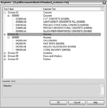
To add keynotes to a Revit model, choose one of the three keynote types from the Annotate tab. In your view, hover your mouse over the various model objects until you find the one you want to note, and click to add the keynote. You'll then be prompted to add a two-joint leader, which will end at a box containing the text of the note you assigned to that material or assembly. Once you've placed the note on the sheet, you'll see a dialog box (Figure 19.53) where you can identify the element you're trying to note if it doesn't already have a note associated with it.
Expand the plus signs until you find your desired keynote and double-click it. Doing so globally associates that particular note with the element or material in the model. As mentioned previously, you need to make this association only once. For example, if you keynote a material called Concrete, then every time you hover the mouse over that material anywhere else in the model with a keynote tag, you'll see the preview graphic of the tag, which reads "Concrete." This way, you can define the materials and assemblies in the model and begin your documentation process.

With the exception of detail components (covered later in this chapter), you can't keynote lines or other 2D information.
Depending on your workflow and style of annotation, you may want to create a legend on each sheet for your keynotes. You might want only the keynotes that are on a given sheet to appear in the legend. Or you may wish to have one legend for the entire project that will show all keynotes used in the project. The legends allow the builder to reference the note number with the text quickly and easily (see Figure 19.54). These lists usually reside on the side of the drawing near the title block information and can take either of two forms. The first type is all-inclusive and shows every note within the project. This style has the benefit of consistency between sheets in the set. The same note will always be in the same location in the list. The other type of keynote list includes only the notes that are present on a particular sheet. This has the advantage of supplying a list of notes customized for each sheet without extraneous information. As you can imagine, this second list can be labor intensive and fraught with opportunities for human error. One of the beauties of Revit is its ability to accurately manage this kind of information for you. We will review how to create both types of lists.
Creating a keynote legend in Revit is simple. Choose the View tab, and in the Legend panel, select Keynote Legend. You'll be prompted to name the legend; enter a name and click OK.
Only two fields are available in a keynote legend, and by default, they are both loaded into the Scheduled Fields pane of the Fields tab. Those fields are as follows:
- Key Value
This field contains the numeric value of the keynote.
- Keynote Text
This field contains the text value for the keynote.
A keynote legend works very much like any other schedule as far as formatting and appearance. By default, the sorting and grouping are already established because the key value is used to sort. The one special item to note is located on the Filter tab. At the bottom of this tab is a feature unique to this type of schedule: a Filter by Sheet check box (shown in Figure 19.55) is available. Checking this box gives you the ability to filter the list specifically for each sheet set.

Figure 19.55. The Filter by Sheet check box located at the bottom of the Filter tab in the Keynote Legend Properties dialog box.
Either legend style you make can be placed again and again on every sheet in the project. The filtered legend style dynamically modifies the note list based on each sheet and the contents on each sheet. As views are added or removed from a sheet or notes are added to the project, the keynote legend updates accordingly. If the keynote is not used in the view placed on the sheet, it will not show up in the legend for that sheet.
Keynote legends are considered another type of legend view: once created, they appear under the Legends branch of the Project Browser.
Revit comes with a keynote family that allows you to produce both keynotes and textnotes. If it is not loaded into your project, you can find it under the Annotations folder in the Imperial or Metric library. The family name is Keynote Tag.rfa. This family has three family types that let you change note styles within the project. You can see the three note styles in Figure 19.56.
The three default styles are Keynote Number, Keynote Number-Boxed, and Keynote Text. Each of these notes pulls information from the text file we discussed earlier in this chapter. We are simply using the flexibility of family types to report different values within the model from the same note. Like any other family, this family can be edited to change the note length, font style, or other attributes to match your office standards.
As we discussed earlier in this chapter, there are three styles of keynotes: element, material, and user. With each of these styles, there are limits to what you can note within Revit—and these three note styles can annotate only objects within Revit. Understanding this is critical to successfully using the keynote system within Revit so you can optimize the value of your predefined notes.
Here's a summary of the most common tasks you can perform with keynotes:
Add notes to elements such as walls, roofs, floors, and families that are a combination of materials or elements
Add notes to the individual materials themselves or to any element that can be given a material
Add notes to detail groups and detail components.
While this is an extensive list and covers most of what happens in Revit, there are a couple of things you cannot tag with the Keynote tool: detail lines; and groups (although you can tag elements within groups).
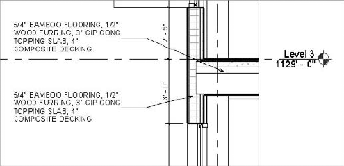
This becomes a critical issue when you begin embellishing details within a model. As a best practice, it is recommended that you optimize the use of detail components and embed them into the project families. Detail components are families created with 2D linework that can be dropped into any view to represent elements that are not directly modeled. For example, blocking that would appear over a window head is not something you would create as a model element, but it is still necessary to show in a section or detail (see Figure 19.57). We cover the technique of creating and noting detail components in Chapter 21, "Moving from Design to Detailed Documentation."

Once you've established your keynote style and made your adjustments to font size and type and linked a keynote TXT file, you can add some notes to the drawing. Adding notes to a drawing from this point is quite simple.
On the Annotate tab, click the Keynote button.
Select Element, Material, or User from the list. In our example, we've selected Material.
When you hover your mouse over the material, Revit will try to identify it. If the material already has a note value defined, Revit will show you a floating note identifying the material.

From here, click to place the arrowhead of the note, click again to locate the joint in the leader, and then click once more to locate the text. If the material is unknown, Revit shows a question mark to tell you this material has not yet been identified in the project.

Locate the note using the same method for materials that are already defined (see Figure 19.58). After you set the text location, Revit will prompt you to select a value from the Keynotes table.
Once you've selected the note for a material, that same note will be applied every time you select that material with a keynote in every other view in the project.
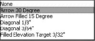
By default, Revit 2010 includes the Open 30 Deg arrow as a standard for your keynotes. However, this is new to the Revit 2010 default template and will not be the case if you are upgrading your template from a previous version. Revit doesn't provide a way to preset arrowhead styles for notes unless you preset them in the project template. After you first insert a note into Revit, select it to add an arrowhead. To do this, select the note and navigate to its properties, and then select Edit Type. Here you can globally set an arrowhead style for any of the keynote family types. Most of the common arrowhead styles can be found in this properties box. Selecting one from the list will change the arrowheads for all of the notes of that type in the project.
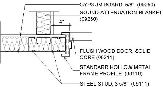
Once you've added a couple of notes, it's an easy process to continue noting the remaining materials in the wall section. The completed section with keynotes looks like Figure 19.59.
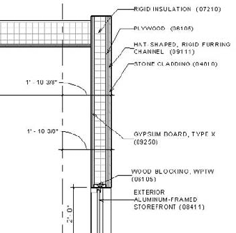
Another way to keynote a drawing is to note by assembly or, within Revit, by element. Keynoting by element means that you are not noting the individual materials as we did in the previous example but the entire assembly at once. So, in lieu of noting plywood and gypsum board, you are noting the entire wall assembly at once. The process to add the notes is very similar.
On the Annotate tab, click the Keynote button.
Select Element, Material, or User from the list. In our example, we've selected Element.
When you hover your cursor over the element or assembly, Revit tries to identify it. If the element already has a note value defined, Revit shows you a floating note identifying the material. From here, click to place the arrowhead of the note, click again to locate the joint in the leader, and finally, click to locate the text. If the material is unknown, Revit shows a question mark to tell you this element has not yet been identified in the project. Locate the note using the same method you used for elements that are already defined, but after you set the text location, Revit prompts you to select a value from the keynotes table.
A wall section noted by element looks like Figure 19.60.
Remember that element, material, and user notes in Revit are different entities and are allowed their own, unique notes. You can note by material, by element, and by user within the same project.
There are a variety of other ways to add notes to a project without adding them directly in a view. Within the properties of elements and materials is a field to predefine a keynote. By putting a value in this field before noting the drawings, you can avoid selecting notes from the keynote list when you are actually annotating a view. All of the notes would be preselected. Depending on the note type, the location for these settings varies.
- Element
This value can be set in the properties of the various families in a Revit project. By selecting a wall, for example, you can select this wall's properties, and then click Edit/New to reach the wall type properties. Under Identity Data, you can then define a keynote (see Figure 19.61). Selecting this field, you will be presented with the same keynote table that you'd receive if you were noting this element in a view. If the note is incorrect for this project or element, you have the option to change the note here as well.
- Material
This value can also be set by clicking the Materials button on the Manage tab. By selecting a material from this list, and then selecting the Identity tab, you can add keynote values directly to your materials (see Figure 19.62). You will again be presented with the familiar Keynote dialog box to select your materials.
- User
User notes are view-specific and cannot be predefined. While it is still possible to annotate only model elements and detail components with user notes, this tool will allow you to note the same element with different notes in separate views. This can be dangerous to the consistency of your notes in your drawings if used inappropriately. The advantage of this note type, however, is if you need to note something differently in one view based on a unique condition. For example, you might need to note a material or color change in a special location or a special flashing or sealant issue around a unique window condition. This will spare you from having to create a new family type simply to add a different note.

Revit does not support more than one keynote.txt file per project, so if you wish to include keynotes from different standards, you can simply add more text entries to the text file that you have for the project and they will all be available immediately within Revit.
- Annotate views.
Room elements are highly useful tools for a number of different applications in a set of documents. Learning how to use them and tag them will help you find areas, create finish schedules, and identify spaces.
- Master It
Once the model has been largely built, you need to start adding information about rooms and finishes. What tools would you use?
- Use schedule keys.
Adding information to the room element is only part of the documentation and design process. Knowing how to schedule that information allows you to communicate effectively with owners and contractors.
- Master It
Tags are used to report information about an element. How do tags work in Revit so that they always report accurate and consistent information about the elements they tag?
- Leverage tags.
Revit supplies you with three ways to annotate your model and the project. Knowing when to use each and planning for them early in the documentation phase saves time and frustration.
- Master It
It is important to understand the relationships between elements and materials in Revit early. How does this help streamline the process of keynoting your project when you reach the documentation phase?
- Understand shared parameters.
Revit lets its users add as many custom parameters to an element as are needed. When those added parameters need to be visible both in schedules as well as in the elements tags, they need to be created as Shared parameters.
- Master It
You added a custom parameter to your door and window elements and wish to schedule and tag it such that each window or door tag displays the information about the hardware set. The schedule works well, but your tags seem to be unable to find the hardware set parameter. What is wrong?
- Add text and keynotes.
No set of drawings is complete without keynotes or textnotes. Understand how to create and modify them for a complete set of documents.
- Master It
You will need to add notes in every stage of design to communicate your design intent on a project. How do you create and modify the notes to ensure accuracy throughout all the sheets in the set?