
In this chapter, we describe the use of an early conceptual mass model to help you understand program fit and the creation of early feasibility studies. You'll see how easy it is to convert a massing study—whether done within Revit or imported from another application—into building elements such as walls, floors, and roofs. The premise of a BIM approach to design is that a fluid workflow can be maintained as you move from early concept models into design development and eventual construction documentation, all the while maintaining the same underlying geometry and design intent. Revit provides specific tools that accommodate early massing model studies for program validation and feasibility studies, which can then be quickly converted to real building elements.
In this chapter, you'll learn to:
Make conceptual designs and early studies in Revit
Build a real building out of a 3D concept mass
Use imported geometry from other applications for massing
Use smart relationships between the building mass and the underlying mass
A project usually starts with a rough conceptualization of first ideas in which the architect's mind wanders between the creativity of fantasy and the reality of customer needs, merged with the influence of the context, the genius loci.
Conceptual designs are the first graphical words an architect exchanges with a client to get approval for the architect's first thoughts and sense the client's taste. When the initial idea is approved, the architect continues in the next stage of development and makes more detailed studies supported by concrete measurements and numbers that prove the applicability and feasibility of the design.
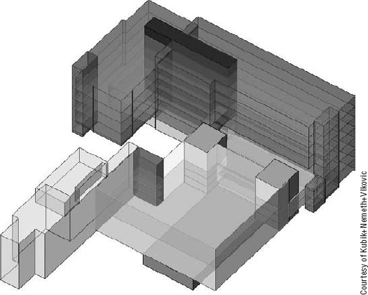
We'll review how this process of initial conceptualization and form finding can be done using Revit. Figure 9.1 shows an example of an early massing study made in Revit. Let's walk through how this workflow is supported.

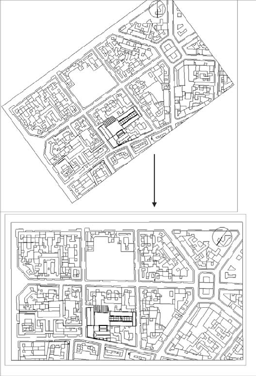
A project usually starts with a client's wishes, vision, and expectations that are described in initial conversations with the architect. A list of program requirements is compiled, listing the types of spaces the building will have and its rough area. The architect then starts gathering information and data about the site—aerial photos, photos of the site and context, site-survey files with land information, and building footprints and blocks. Using site analysis, program requirements, and creativity, the architect proceeds to study what shape and size building fits best. Variations of the design are studied, analyzed, critiqued, and presented to the client.
Getting site data into the digital model is the first step in moving from loose napkin sketches to a real project. By importing DWG or DGN site information into Revit or using a CSV points files, you'll have a real-world underlay from which to work. (For small projects, this can also be a scanned image of a hand-drawn site situation.)
CAD drawings with site information usually come with a rich amount of information that needs to be culled. Using the Visibility/Graphic Overrides dialog box, after having imported the DWG or DGN file, you can hide unnecessary layers to make the drawings more legible. Setting the correct scale and orientation of the site relative to the building will be the most critical initial steps, and they should be carefully considered during the import.
In the Import CAD Formats dialog box, setting the Import units to Auto-Detect usually works well if the CAD file was drawn correctly, that is, at 1:1 scale. If the drawing was scaled, you may find that the scale of the imported file is incorrect. If this is the case, you can rescale the image using Element Properties, in the Instance Properties dialog box.
The next step is to deal with the orientation of the imported site plan. Maps are usually created so that north is always at the top, and that is how site information should be displayed in final documents. However, when you're working on developing a site plan, you'll probably prefer to work in a way that is most comfortable for you, in a way that the site is oriented parallel to your computer screen (meaning you don't have work under some strange angles)—not to true north.
Suppose you're starting your design study and you open a site plan view to import the CAD file with the site. An imported CAD drawing usually comes in its original coordinates' orientation, with north and south in the vertical axis.
If you open the view's properties, you'll notice that the Orientation parameter indicates Project North.
By default, the orientation of a view is set to Project North. By changing the Orientation parameter to True North and rotating the True North setting, you can work in a comfortably oriented plan relative to your screen.
In the View Properties dialog box of a plan view, change the Orientation parameter to True North, and rotate true north using Manage

This procedure is more than enough if you don't intend to send information back to the person you received the file from. However, if you're collaborating with a civil engineer and need to send back the building footprint or an early mass study, you need to establish a connection between the two files so they have the same coordinates. This can be achieved using Linking (an option during the import) as well as the Acquire Coordinates functionality.
You can choose an automated or manual placement of the imported file in your Revit project. With Automatically Place (under the Positioning drop-down in the Import dialog box) you have the following options:
- Auto - Center to Center
Aligns the 3D center points of both models.
- Auto - Origin to Origin
Places the world origin of the linked file at the Revit model's origin point. If the linked model was created far from the origin point, linking with this option may put the linked file far away from the main model.
- Auto - By Shared Coordinates
Places a linked Revit file according to the shared coordinate system created between the two files (this is available only if you're linking files). If no shared coordinate exist between the two files, Revit alerts you and uses the Auto - Center to Center positioning. The Shared Coordinates settings can be found in the Tools drop-down menu; you have the following options:
- Acquire Coordinates
Allows you to take the coordinates of the linked file into the host model. There is no change to the host model's internal coordinates; however, the host model acquires the true north of the linked model and its Origin setting.
- Publish Coordinates
Allows you to publish the Origin and True North settings to your linked model. Revit understands that there may be other things in your linked file, and you may not want this to be a global change to the linked file. An additional dialog box appears that gives you the option to name separate locations for each set of coordinates.
- Specify Coordinates at a Point
Allows you to manually key in X, Y, and Z coordinates relative to the origin or define where you want your (0,0,0) point to be.
- Report Shared Coordinates
Shows the E/W (east–west) (X), N/S (north–south) (Y), and elevation (Z) coordinates of any point in the model.
- Manual - Origin
The imported document's origin is centered on the cursor.
- Manual - Base Point
The imported document's base point is centered on the cursor. Use this option only for AutoCAD 2009 or later files that have a defined base point.
- Manual - Center
Sets the cursor at the center of the imported geometry. You can drag the imported geometry to its location.
You can import a CAD file so that it appears in all views of your project, or you can import it so that it is visible only in the current view in which you are importing it. You will find these options at the left side of the dialog box.
Remember that for topography files, as an exception to the rule, you should not select the Current View Only option because you will not be able to convert the imported file into topography. This might be slightly counterintuitive because this is exactly a case where you would logically import it only in site view because you don't need the topography in any other view (and thus the Current View Only option would have rather been the logical way to proceed). However, because of some settings concerning the site in Revit, you will need to remember this exception. In any other case, if you need to see an imported file just in one view, select the Current View Only option.
If you forget this rule during the import and import the site plan using the Current View Only option, we advise that you delete the import and re-import the file, making sure that the Current View Only option is not checked. As you will probably not want the site file to be visible in all other views, you can turn its visibility off in the other views later.
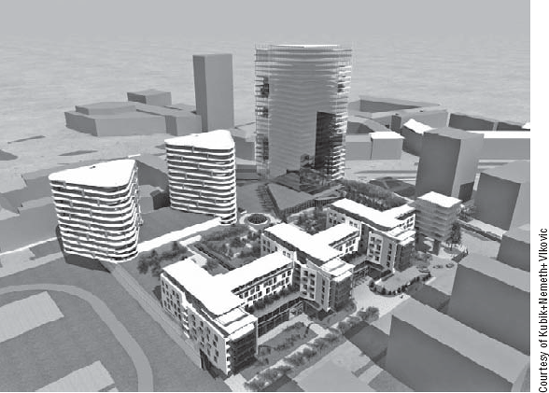
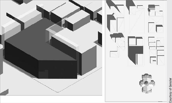
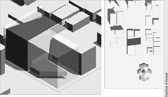
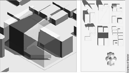
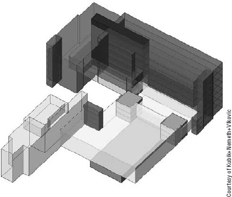
After positioning an imported CAD file in your site plan and reorienting it to true north, you can start building a 3D environment using the massing tools. The base shapes of buildings in the CAD file can be used to generate a massing model of the surrounding site quickly. Figures 9.2 through 9.5 show examples of generic massing of context buildings. Use photos or actual data to establish building heights.
To make a 3D study of the surrounding site, use the In-Place Massing features and begin developing solids out of the existing geometry:

Many of the activities in early design revolve around exploring the commercial viability of the site and figuring out the right mix of uses (for example, residential versus office versus retail). All these uses have different economic returns. Zoning regulations can be complicated in how they allow different amounts of total development based on the mix ratio. In essence, two numbers govern almost all urban properties: floor area ratio (FAR) and lot coverage ratio (LCR). FAR is a number that says how many multiples of the site area the building area can be. LCR specifies the percentage area of the site that can be covered by the building footprint. Usually the architect is required to maximize the FAR by determining the right mix of uses placed at the right location on the site.
At this stage, the problem is not only about forms or shapes but also about the program, construction costs, rents, and the functional distribution on the site horizontally and vertically. The architect usually attempts to determine what physical forms, in what location, and with what use will provide the best economic return to the owner. This study then needs to be consolidated and documented. While studying this problem, the architect may generate tens if not hundreds of slightly different alternatives for numerical comparative purposes. A few of the most promising are then developed further for client and authority presentation purposes.
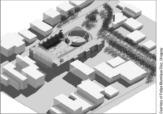
At early stages in design, you need to check the program and how well your proposed design fits into it. A program can be less or more precise, depending on the client and the task in question. It can be as bold as 15,000 sq. ft. (4,570 sq. meters) offices, 40,000 sq. ft. (12,200 sq. meters) hotel space, and 20,000 sq. ft. (6,100 sq. meters) retail space for a bigger complex, or it can be an exact number of rooms and spaces when working on one building. Figure 9.5 shows an early massing study annotated to show usage and areas.
The next step is to propose multiple solutions to the client, so proposals with different mixes of functions and spatial solutions can be reviewed and analyzed. This is where the Design Options tools you'll learn about in Chapter 10, "Working with Design Options," come in handy.

Figure 9.5. Early study documenting maximum allowed heights and total square footage of a proposed solution.
Architects are constantly thinking about architectural expression, fitting in the site, and accommodating the program. They're also evaluating whether the client's requirements can fit the allowed buildable area and height of the site, zoning regulations, land uses, traffic requirements (they usually always want more), and information about the number of parking spaces and other support functionalities. This phase of the project can also involve shadow studies and energy modeling, as discussed in Chapter 18, "Evaluating Your Preliminary Design: Sustainability."
Creating Multiple Massing Study Design Options
Here is a suggested workflow based on a real-world use case.
The architectural firm Gensler created an option set with three options, each with a distinct name. They duplicated the 3D views, made three different variations of the design and schedules to document project information of the three design options early on. In each view, the Visibility/Graphic Overrides were set to display only one option at the time (one set to Option 1, another to Option 2, and the third to Option 3). Doing so not only visually described the new option but also presented the data behind each design.
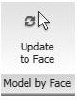
After a series of iterations and tweaking, the client makes up their mind. One of the solutions is selected, and you're ready to move early massing studies into a real building project. Here is where the Model by Face tools comes into play. With these tools, you can use the mass as a basis for actual building elements and move to the next stage of design, attaching walls, floors, and roofs to the massing surfaces.
This approach has two major advantages over traditional 3D systems:
The need to re-create the digital data from scratch is eliminated. Instead of building a new project with walls, floors, and the like, you simply use the created mass as a reference
A connection between the building elements made by referencing the mass and the mass itself is established, so that the massing design can change later, and this will automatically update the building elements made out of its faces or floor slices
The nice thing about this workflow is that it also supports the import of massing elements or studies from other tools, such as AutoCAD 2010, Maya, Rhino, 3ds Max, Inventor, or SketchUp, and converts them into Revit mass elements, to which you can then attach walls, floors, and roofs and thus convert the mass into a real building.
Chapter 8, "Concept Massing Studies," discussed the principles of conceptual form making and rationalization, so by now you should have a good understanding of how to create a mass element or an entire massing study using in-place massing or loaded mass families.
In this chapter we'll focus on how to apply building components to your massing—in the conceptual design environment and in the project. The tools for placing mass floors, roofs, curtain systems, walls, and floors are under the Model by Face drop-down in the Conceptual Mass tab on the Massing & Site tab.

Let's get an overview of the available tools and then examine their real-life application.

Assuming you've created a mass study in which you defined the basic volumes and shapes that will form your building or complex of buildings, you're ready to start setting up levels. Depending on the type of building you're making, code regulations, and functional usage, you can begin to lay out levels for the building. Let's say the maximum allowed regulated height for your building is 70′ (22m), and your building is a hotel, which will usually have a 10′ (3m) floor-to-floor height. In that case, you can get approximately seven levels.
Switch to any elevation view, and using the Level tool, start adding as many levels as your building needs to have. It's obviously much easier to copy a level graphically using the Multiple Copy or Array command than to manually draw a level seven, eight, or as many times as you need it. However, if you use the Copy or Array method for level creation, you won't create actual floor plan views associated with each of the levels, something that would automatically be done when you manually draw levels. (The difference between drawing and copying a level was covered in Chapter 3.) If that's okay with you, and you don't need floor plan views for each of the levels, then all is well and you can go ahead. If not, and you do wish to have a relevant floor plan generated for each level you are creating, you can either use the Level tool and draw each level or use the Copy method to create levels but then additionally create floor plans from those levels by using the View/Floor Plan tool and selecting which levels should have a floor plan view associated with them.
Once you have established the number of levels your building will have, select the mass and click the Mass Floor button from the Modify Mass tab. (It is good to do this in a 3D view, as you will instantly understand what that tool does.) Upon clicking the Mass Floor button, a dialog box will appear with a list of all available levels in the project. Click the checkbox next to each of the levels you want to generate floor areas for. If you check all levels, a mass floor will be created for each level that can be calculated for area. If you want to skip a level because of double room height, for example, don't check that level. You can do this for all masses at the same time or separately for each one. You can also add or remove levels later: anything in Revit can be changed at any time.
Select the levels that intersect your mass and that you want to get area information from, and click OK. You will see the mass sliced by all the levels you selected, and mass floors are indicated on the mass.
Figure 9.6 shows Mass Floors being applied to the main building only. In Figure 9.7, all other masses representing other buildings have also been sliced by the Mass Floors tool.
Revit is fantastic because you can add, delete, and reshuffle levels at any moment in your project development without needing to redo work or losing any invested work.
The slicing of masses done by the Mass Floors tool doesn't just visually help you understand the number of floors and divisions—it also provides numerical information essential for early conceptual analysis. With the help of this tool, you can find out the following:
Floor area
Exterior surface area
Floor perimeter
Floor volume
Usage
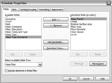
The Mass Floor Area parameter can be added to schedules, so that you can call out and schedule all parameters associated with mass floors (Figure 9.8).
An additional improvement allows you to get information about the floor perimeter and the exterior surface area (Figure 9.9).
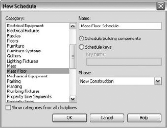
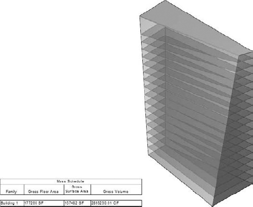
You can calculate gross floor area, surface area, and volume, and for that you make a schedule of the Mass category
You can also calculate and schedule floor area, exterior surface area, floor perimeter, floor volume, usage, and some additional parameters inherited from the mass, all per individual level—and to do that you schedule the Mass Floor category
This provides data that can help you easily create a conceptual analysis and validate the program fit. By scheduling, sorting, and filtering the data of mass floors, you can find out the exterior skin material for each usage on each floor and calculate its percentage against the entire exterior surface of the building. You can do similar calculations for the floor area to determine the total usage of various functions and their percentage relative to the total usable area of the building.
Even though the floor area faces calculate volumetric slices of the mass, they will not show up as 3D volumes. Only the floor area surface geometry becomes a new element in the model.
You can schedule the parameters and values of the masses like you can for any other Revit element. In the earliest phase of the project, you'll probably want to schedule the functional zones. To create an understandable schedule, it's a good idea to give the mass elements you created names according to their function—Hotel, Conference Hall, Parking, Restaurants, and so on—and assign them different colors (materials) so it's easy to visually represent the data. If you need to rename the mass element once it is created, you can do that from the Project Browser—find the mass element in question and rename it using the context menu. You can also add project parameters to the mass elements, such as Public or Private Space, Department, and so on. If you wish to tag those new parameters so that they are shown in a mass tag, you must make them shared parameters and add them in the Massing Tag family. See Chapter 19 to learn about shared parameters and their applicability.
Out of the box, the Mass category in Revit can report the following numeric properties:
Gross floor area
Gross surface
Gross volume
If you create an initial mass study and schedule the mass elements, the schedule reports the gross surface area and gross volume of the entire shape, as shown in Figure 9.10. Note that the Gross Floor Area field is blank: the reason for that is that you can't schedule the gross floor area without first adding levels and creating mass floors, as explained at the beginning of the chapter.
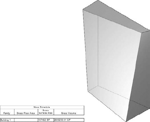
Figure 9.10. Example of a mass element without mass floors applied (no floor area faces generated as of yet).
By defining levels and creating floor area faces using the Mass Floor tool, the floor area slices will show in the mass, and the missing information about the gross floor area will be automatically filled in the schedule (Figure 9.11).
The gross floor area of the mass is the sum of all the mass floor slices related to any given mass element. Periodically, you need to get separate data about the floor area per floor, sorted and grouped by use or function. This is possible by creating a schedule for the Mass Floor category (Figure 9.12).
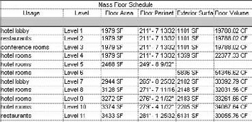
Figure 9.12. Scheduling new parameters can help you make a more accurate conceptual analysis about the usage of space and materials.
The reported values are useful for further conceptual analysis, as you can apply different cost factors for different exterior skins. For example, you can get a good idea about the cost of making the last five floors of your building using glass skin versus having them all be solid walls.
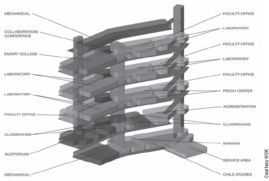
The massing tools in Revit have been extensively used by many architects. Figure 9.13 shows a project of the firm HOK in which they used the massing tools to produce colored diagrams that are great for explaining to the client the spatial organization of the project. This book is black and white, so you will need to apply your imagination as to how such a color diagram looks. Know that investors love this simple but informative way of understanding functional distribution.
Because you can quickly generate metrics and graphics showing the functional distribution of program elements, you should be able to get feedback on the fitness of the design early on. This will in turn allow you to fine-tune the design and make sure you're keeping pace with the client's requirements. Once you've built a parametric massing model, the elements are all adjustable in size and shape, and any change you make will instantly be reflected in the visual and schedule data (Figure 9.14).

After you've reviewed a couple of design options with the client, a decision is made and you need to move forward into the real project. Moving to the next stage is simple: you can use the mass to generate building components using specially designed tools. Let's look at these tools now.
You can start using the mass to generate real building elements such as walls. For that you will use the Model by Face
Many of the rules and principles behind standard wall creation should be followed here as well. It's important to correctly set your wall location prior to applying it in order to minimize rework later. Of course, if you make a mistake, you can always fix that later. How you build the mass—to represent the outermost envelope or to represent the interior envelope—will determine how you want to set the location line for your walls. Use the exterior face if you modeled the massing to the exterior envelope of construction. Keep these limitations in mind:
Any wall in Revit can be converted into a curtain wall. Unfortunately, this isn't the case with walls created with the Wall by Face option. To make curtain walls, you need to use the Curtain System tool in the Model by Face drop-down list
You can't edit the profile of a wall by face (using the Edit Profile tool available to standard walls)—meaning you will not be able to freely carve out shapes from a wall. To do that, you must change the shape of the underlying mass first
Only after you've used the Mass Floor tool to generate mass floor area faces can you apply real floor elements. Select Model by Face
To accommodate floor creation in a tower with many floors, for example, you can check the Select Multiple option on the Options bar. You can then begin selecting all the floor area faces to which you wish to apply floors and finish with the Create Floors tool.
The Mass Floor tool slices the mass horizontally, creating horizontal floor plates by default. If you need floors to be sloped (such as ramps), you can always slope them later after applying Floors and the Shape Editing tools available when a floor is selected, or you can edit the sketch of the floor and add a slope arrow when in Sketch mode of the floor (Figure 9.15).
It's worth mentioning that when you create a floor by face, the Options bar includes an Offset parameter.
This isn't the vertical offset of the floor from the level you can find in the Floor properties; it's an offset of the floor sketch from the current floor area boundary. If you add a positive value to the offset, the floor plate becomes smaller than the actual floor area (Figure 9.16).

You've learned how easy it is to apply walls and floors to massing faces. Roofs follow the same basic principles but are more flexible. You can create roofs by face on planar faces, arcs, or other shapes created by extrusions, revolves, sweeps, and blends.
Note these limitations:
You can't select a vertical face to create a roof
Once a roof is created using the Model by Face: Roofs method, you can't edit its sketch to change its shape in plan. If you created a roof by face and need to change its sketch, you must change the shape of the underlying mass from which the roof has been derived; only in that way can you affect the shape of the created roof
Curtain systems are a handy tool for dividing a faç.ade into regular intervals of panels and mullions. With one click, you can convert the face of a mass into a curtain system with predefined parameters to match your needs. Curtain systems can be applied to any face and are composed of grids, panels, and mullions. Make sure the curtain system type you choose has a predefined Curtain Grid layout.
Keep these limitations in mind:
You can't edit curtain system sketches. A curtain system made by face requires editing the shape of the underlying mass
You can't always predict the XY coordinate system applied to the face. You may have to make new types in order to meet your requirements
Only masses that are planar or curved in one direction can host custom curtain panels. Compound curved systems have to use the default system panel
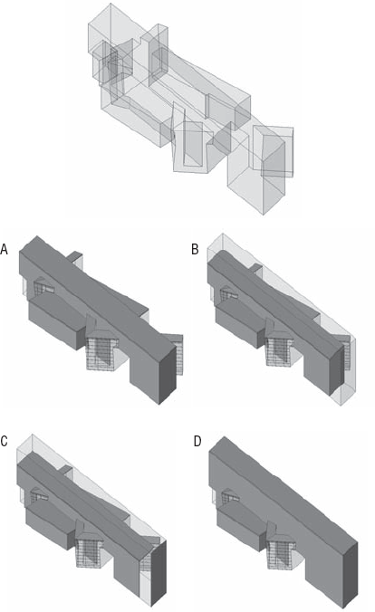
It's important that your mass model be modeled properly from a geometrical point of view in order to support accurate area reporting and downstream applications of walls, floor, and roofs. Look at the towers shown in Figure 9.17. If you simply draw the two towers and schedule them, the schedule reports the values for the individual towers.

If you move the position of the towers so that they intersect, the schedule reports the same calculated values: Revit doesn't join the geometries and eliminate the overlapping areas automatically (Figure 9.18). If you place different masses that aren't joined and overlap, when you use the Floor by Face tool the intersecting portions of floor slabs overlap and cause duplicate area calculations. To resolve this issue, you need to join geometry.
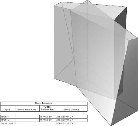
Figure 9.18. Mass forms intersect but are still not joined; the schedule still reports the sum of the area and volume.


Joining the masses creates a relationship between the two masses. This means that if you move the location or edit the shape of one, the joined geometry (Boolean) automatically updates. Only in cases where you move one mass completely away from the other mass will you get an error message that the two masses don't intersect anymore, and you will need to use the Unjoin Geometry option to fix the error.
Once the masses have been joined, you can begin to apply elements to the mass surfaces (Figure 9.20).
The Curtain System by Face method is great if you only need to lay out equal-spaced lines in two directions, but what if you want to create more complex surface patterns and give 3D articulation to that pattern? This is where the new pattern-based curtain panel family comes into play. As we mentioned in the previous chapter, any surface in the conceptual design environment can be divided and patterned with any of the precooked patterns provided. These patterns are 2D by default, but they can be made 3D very easily. Once you have a 3D pattern family, you simply load it into the massing family, and it will be available in the type selector when any divided surface is selected. We'll take you through an example.
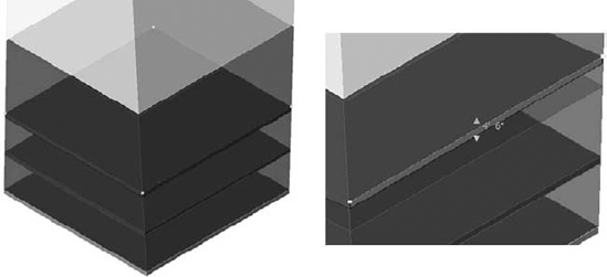
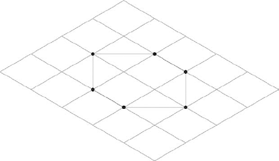
Before jumping in, keep in mind that a surface has four levels of representation: the original surface, the UV division of the surface, a pattern that is "stitched" onto the UV division, and components that can fill in a pattern. Figure 9.21 shows the progression, from left to right. The most important thing to keep in mind is that a pattern is always made of straight segments that span from node to node along a surface—it is not made of segments that follow the curvature of a surface. This fact is important, as this is what truly makes a surface rational and eventually buildable.
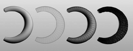
Figure 9.21. From left to right: original surface, divided surface, patterned surface, component on patterned surface.
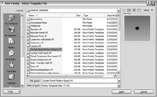
To start, from the application menu, choose New
Figure 9.22 shows an example of the default rectangular pattern family with the reference lines selected. The reference points can be clearly seen.
The grid represents an abstract version of a divided surface. If you select it and open the Instance properties, you can adjust the UV spacing. You can also swap the pattern type using the type selector.
Figure 9.23 shows a hexagon pattern. The reference lines are important features of these families—these are the linear elements that span between points as the points adapt to surfaces. Using the reference lines to create form will cause the form to adapt to surfaces as well. Let's try one out.
Open a new
Curtain Panel Pattern Based.rftfile.Select the grid and change the type to Triangle using the type selector.
Place a reference point on one of the reference lines—this will be the host for a swept profile.

Select the point to set it as the active work plane; then sketch a circle with a 3″ radius around the middle of the reference line.
Select the circle and the chain of reference lines that make up the triangle, and then click the Create Form button. You should end up with a sweep along the triangle.

Create a new conceptual mass family and create a simple form. Divide a surface of the form, and then apply a triangle pattern to the form.
Go back to the triangle family and load it into the mass family.
Select the divided surface, and use the type selector to change the triangle pattern to use your custom panel—you should see the name of your family at the bottom of the list.

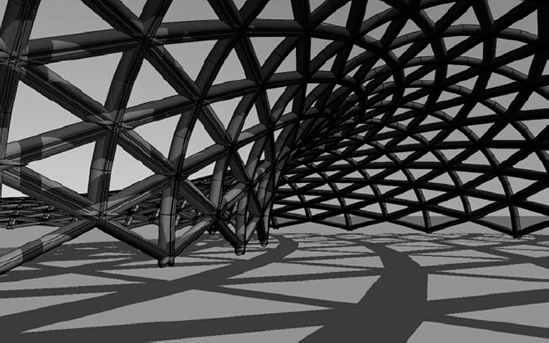
As you can see from Figure 9.24, this feature is very powerful way to propagate a family across a façade. The patterns available offer flexibility of formal expression, and you should feel inspired to give them a try.
You can use various applications to create geometry to be imported into Revit for massing. This section looks at using SketchUp, Autodesk Maya, Rhinoceros, Autodesk 3ds Max, Autodesk Inventor, AutoCAD 2010, and many more.
SketchUp is a fantastic piece of software. It's considered by many to be a great concept modeling and visualization tool that is easy to use, produces great results, and really feels architectural. Many architects adore SketchUp for conceptual studies or early images of design ideas. Revit users use SketchUp to make initial massing and conceptual studies to produce nice graphic outputs for their clients. They can then move the model into Revit for the documentation phase.
SketchUp files can be imported in either of two file formats, which are tied to different workflows and expectations:
- SKP
Use this format if you've created a complex geometric element in SketchUp that is pretty much final, and you just need to import it into Revit using the direct import of the SKP file. An example is a building with a complex shape or roof that you couldn't easily do in Revit.
- DWG
If you expect a dynamic workflow where the models need to move back and forth and maintain some intelligence, use file linking and link in the DWG files. This way, if the DWG changes, the model will update to show the latest version of the DWG.
Here is how we suggest working with a SketchUp file:
In SketchUp, make a quick and easy initial concept design like the one shown in Figure 9.25, and save it.
Start a new massing by using the In-Place Mass tool in the Massing & Site tab, and then import the file from the Insert tab, using the Import CAD button. This will open the Import CAD Formats dialog box (Figure 9.26).
Switch to 3D view, and switch the model graphics of the view to Shaded with Edges. The SketchUp model appears in Revit. You can also activate shadows to see the model better (Figure 9.27).


Often, when you finish the mass family after importing the SKP file, you'll get a warning message. It's important to read this message in order to understand the future expectations for the import. If a mass family imports only nonvolumetric geometry, you can't create floor area faces in Revit. This is the case with any imports that come from surface or polymesh modeling applications. When imported into Revit, NURBS surfaces and solids can to be fully understood by Revit, and you can use them to generate the mass floor area faces and all future reporting needed for conceptual studies. Maya and Rhinoceros deliver good NURBS surfaces for this workflow.
Rhinoceros (known popularly as Rhino) is a neat application that many architects love for the powerful shapes it can create and its relative ease of use. Rhinoceros produces NURBS surfaces that can be easily imported and used as a reference to create a building out of the Rhino massing concept.
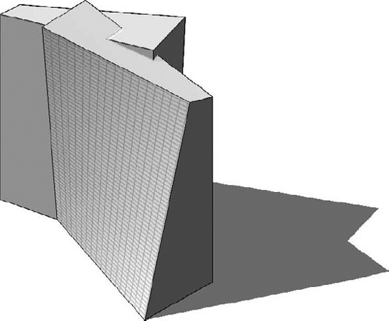
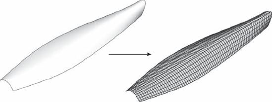
You can use Rhino to create concept studies or a complex-shaped building element. As an example, a draped form was created using Rhino and then imported into a Revit massing element (see Figure 9.28), just as you'd do with a SketchUp import. The form was then used as a reference and a curtain system by face was applied to it to generate the roof in Revit.
Rhino models are imported in Revit as SAT files. To import a SAT file from Rhino into Revit, the best approach is to make a mass family in the project environment and import the SAT file while in mass editing mode. This allows Revit to use the imported geometry for mass floor area faces and to perform other calculations and cuts in section and plan.
This warning can safely be ignored. Finish the family; then, from the Massing & Site tab, select the Model by Face
The new object—a curtain system—is generated from the underlying geometry (Figure 9.29). It's important to understand that glass panels don't conform to the surface—the panels remain planar and attempt to fit the surface as best they can. So, as the panel cell size gets smaller, deviance decreases. You can always change the type later, just as you can for any element in Revit. Once you're happy with the type and the size of the panels, you can apply mullions. Depending on the complexity of the imported file, this can take up to a few minutes—but don't worry, it's a one-time action! Note that tighter grids give better results but also increase the processing time.
As technologies become more powerful, they have the ability to influence trends in many industries, including architecture. Organic, free-form, generative buildings are all over the architectural magazines: this in a way is provoked by the fact that building technologies have become more sophisticated but also because modeling tools to create such forms have become better and easier to use. And while no software can make something beautiful unless it is in the hands of a creative person, these inspiring tools certainly capture the creative mind of talented architects.
In the myriad of available modeling tools today, the question is not only if you can make a shape or inspiring design but how. Maya is considered one of the best tools with a most artistic approach to form finding. No wonder that it started to capture the mindshare of many famous architects and is being implemented in the curricula of the most advanced architectural schools that teach generative techniques and methodologies of computational modeling.
Maya not only helps artists explore forms that are approximations or alternatives to creative visions but in itself sparks ideas and forms not previously explored or considered in a creative process.
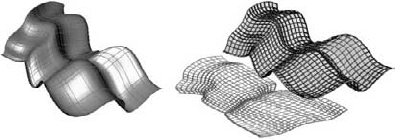
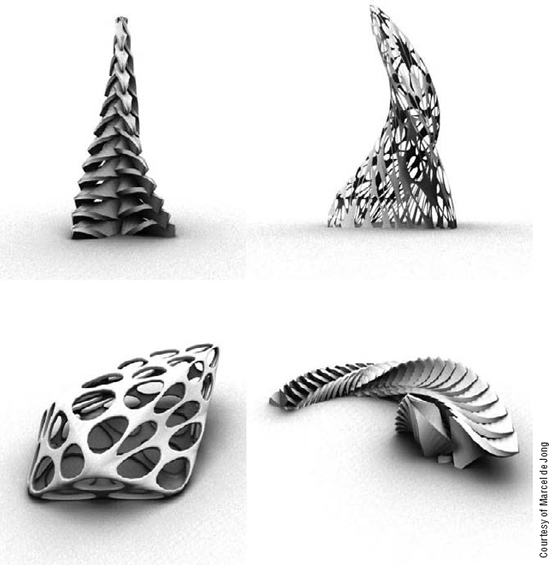
Maya can create the most amazing shapes (Figure 9.30) and supports three major types of geometry: polymeshes, NURBS surfaces, and subdivision surfaces. You can import any of those into Revit, but if you want to leverage the full power of Revit to get area, volume, and skin calculations from the Maya model, you'll get best results by using NURBS in Maya.
The workflow from Maya to Revit is either via DWG directly to Revit or via AutoCAD where the DWG is converted into a SAT file and then imported into Revit. As a general rule, use the latter only in cases where you have trouble importing the DWG created with the plug-in.
The DWG export from Maya is not native in Maya but is a separate plug-in and can be found at the Autodesk Labs website: http://labs.autodesk.com/utilities/maya_export_dwg/.
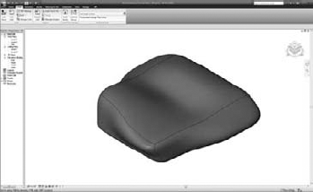
Autodesk Inventor is a software solution for the manufacturing industry, but it starts to provoke a growing interest among architects for its parametric rules-based form generation as well as for its fabrication capabilities. Using rule-based techniques, you can create a complex conceptual mass in Inventor and then use them in Revit to make initial conceptual analysis, mass floor areas, volumes, and so on and then move the concept to a real building by creating elements by faces, just as you can from the other modelers (Figure 9.31). You should export the conceptual mass done in Inventor in SAT file format to be able to import it in Revit.
Inventor can serve later in the stage of creation of implementation documentation and fabrication details (Figure 9.32). You can design, for example, your curtain wall layout in Revit but can make fabrication exact drawings of each of the elements using Inventor.


New to the 2010 release of AutoCAD are some new free-form modeling tools that allow you to rapidly convert boxy shapes into smooth subdivision surfaces. These forms can be imported into Revit and work well with the Model by Face tools.
The new Mesh Modeler in AutoCAD is based on subdivision surfaces, and it allows you to make free-form shapes that would otherwise be difficult to model with NURBS, polygons, or solids. These tools provide a simple and intuitive set of modeling techniques, based on pushing and pulling vertices, edges, or faces of a mesh. This is done through direct manipulation of the mesh, which is quite nice. The modeler then has the ability to smooth the mesh, making an approximation of a curve with different levels of complexity. This can then be used in a Revit massing family (Figure 9.33).
When you import a mesh into Revit from Rhino, Max, Maya, SketchUp, or a similar application, you can only use the surface of the imported object to apply faces, and you cannot get floor area calculations. With irregular or complex geometries, where walls may not be vertical, or where the concepts of wall, floor, and roof become blurry, generating a floor without a mass may become unfeasible. AutoCAD 2010 introduced a new topology that replaces the old mesh and can be directly manipulated and smoothened with a very simple set of commands. These meshes can be converted into solids or surfaces within AutoCAD and then imported into Revit as .dwg files and used to host walls, floors, and roofs using the Model by Face tools.
- Make conceptual designs and early studies in Revit.
You can use massing studies to validate a design against the program requirements.
- Master It
Conceptual modeling is used early in the design process to explore the building shape and building program. How do you approach schematic design using Revit and perform feasibility studies?
- Build a real building out of a 3D concept mass.
Moving from massing to actual building components is easily done with Revit.
- Master It
You have the basic massing nailed down, and now you need to study more details such as wall and window fenestrations. How do you approach this with Revit?
- Use imported geometry from other applications for massing.
Make your own conceptual massing forms using the new Revit conceptual design tools.
- Master It
How can you reuse conceptual models created in other modeling applications and turn them into a measurable and documentable building in Revit?
- Use smart relationships between the building mass and the underlying mass.
Use the update tools to re-sync building elements with changes to the underlying mass surfaces. With Revit, you can change the mass and know that most objects can be recomputed to match the form.
- Master It
Change your massing model to explore design alternatives.