In this chapter you'll explore the early stages of design and how to generate initial massing studies used to iterate on design concepts. We introduce you to the tools in Revit that support early conceptual design workflows where the form is not only explored but also rationalized. Revit allows you to maintain continuity in design data as you move from the massing study into real building elements, making it possible to easily transform massing studies into buildings that can be documented and eventually built. We discuss various approaches for creating massing studies and the underlying principles of creating parametric mass elements using the new conceptual design environment. We will also introduce you to a method for rationalizing massing surfaces.
In this chapter, you'll learn to:
Understand massing workflows
Start a conceptual massing study
Understand form making and rationalization
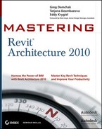
There are many ways to start a new design. It often starts as a series of early sketches that convey form and function related to the project brief. These first ideas often encapsulate the essence of the design and, unless some unforeseen changes are demanded in the design, are usually easily recognizable in the final building. Many architects are known for the remarkable similarity between the first sketches of their ideas and the final outcome of the built buildings, as can be seen in drawings by architects such as Frank Gehry, Jorn Utzon, Daniel Libeskind, Frank Lloyd Wright, and countless others. Figure 8.1 shows a hand sketch using very gestural lines, tones, and hatches. The ability to sketch freely and with gestural expression is a fundamental aspect of design iteration and has been part of the architectural profession for centuries.
Architects have long realized that the only way to make investors buy into their early ideas and designs is to make those early designs understandable to them. Many investors have difficulty reading technical drawings, so architects use creative methods to communicate the design, the space, and the experience of that space from the early stages of the design on. Perspective drawings, photo collages, and 3D physical models made of wood, Styrofoam, cardboard, balsa, Plexiglas, and metals are all used to help the client, and sometimes the public, understand the implications of a given design. Increasingly, with the pervasive use of digital tools, 3D printed models and laser cut models are being used.
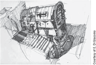
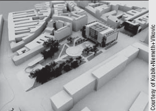
In more sophisticated design studios, physical models are constructed so that the design can be evaluated by deconstructing the model into parts representing different levels or functional parts of the building. This allows people to examine individual stages of construction and integrated systems. Models can range in fidelity from very rough massing studies to highly photorealistic models, as Figure 8.2 demonstrates.
Three-dimensional physical models offer some obvious advantages for conveying design intent:
You get an immediate feel for proportion, scale, and composition
You get a sense of spatial volume
Light and shadow can be easily simulated by holding a real lamp near the model and observing the shadows
If you model the surrounding site, you can easily understand how your design relates to its context
Three-dimensional physical models also have some potential disadvantages:
They take a lot of time and patience to create
They require space for creation as well as storage
They can't handle design options easily and thereby require building multiple models to convey each design option
They require manual work—both in the physical modeling and in performing calculations of area and space
They can be costly in terms of skilled personnel, materials, and equipment
As clients become more demanding, they aren't satisfied with just understanding how the future building will look but also want to know how the building will perform in terms of lifecycle costs. With sustainability now an integral part of the design process, they also need to understand how the building will function over time from an energy point of view. BIM makes this process much more viable, as you are building much more than a mere physical model. The forms you make in Revit can be used to do early sun studies, area analysis, and energy analysis. Multiple iterations can be generated for comparison. Making a final decision is not always easy, but the ability to compare and contrast multiple proposed solutions in order to arrive at an optimized design solution makes it easier for you and your clients.
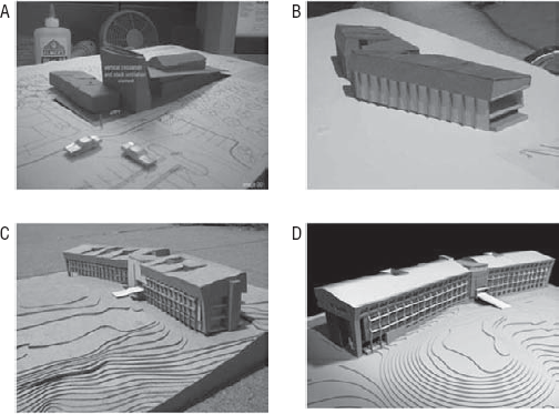
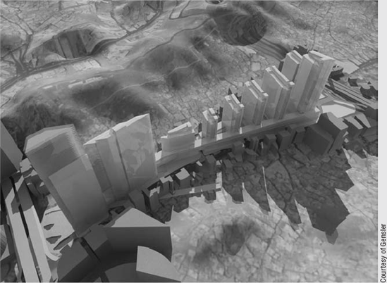
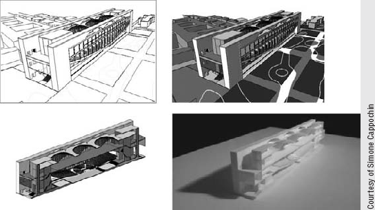
To accommodate all these requirements, architects and owners need to analyze the building and experience it in the early stages of design before it's ever built. Traditional hand-built models don't provide this kind of analytical flexibility. This is where using digital models backed up by real data come into play. See Figure 8.3.
Regardless of how a massing study is done (digitally or in a physical medium), there has always been a break in the workflow between the conceptual design phase and the next phase of more detailed analysis of how the building will behave and be constructed. In the case of a built physical massing model, once you've built one, moving that model forward into more detailed design requires that you create a digital project from scratch, usually in a tool such as AutoCAD. The 3D model is not inherently reusable downstream.
Even when you make a study using digital tools such as Rhinoceros, SketchUp, Form-Z, Maya, or 3ds Max, in order to document those studies you still need to start from scratch because these tools are mainly modelers—not architectural documentation tools—and the data created with these tools is not reusable in any intelligent manner. In these cases, the documentation phase traditionally occurs in the form of 2D drawings produced with tools such as AutoCAD.
With the advent of building information modeling, this is all changing, as you can now carry a conceptual model through to construction documentation in one environment. Indeed, an important aspect of using BIM is the ability to move and reuse previously created data throughout the design process, from start to finish—without having to start over. Revit provides a set of tools for converting an abstract mass form into a full-fledged building information model. In Revit, a specific set of tools keeps the design process integrated. For early conceptual studies, you can create models natively within Revit using the conceptual design tools, or by importing geometric massing studies created in other applications. Regardless of how you create the concept massing studies (either within or outside of Revit), they can later be used to generate building elements such as walls, floors, and roofs.
Here are some common scenarios where using Revit massing tools makes sense.
Site Studies: Using Massing to Quickly Build the Context Environment around the Building
You can use Revit's massing tools to quickly model the surrounding context of your building to get a feel for how it fits the site. This is a standard practice used to demonstrate how your design relates to its environment. Once you have modeled the environment around your building, you can generate walkthrough cameras that move around your building so you can experience it from different points of view. You can also make solar studies to better understand how your building affects the environment and how the environment affects your design.
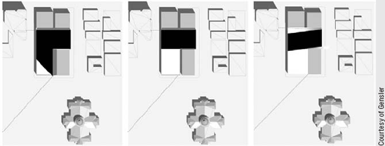
Massing Studies for Testing Different Design Options
You can do a quick conceptual massing study to work out a functional design arrangement, make more options, and look for an optimal solution. For each design, separate masses can be made and given color to indicate their function. This allows you to see spatial relationships in simplified geometric forms but also get precise area and volume values for each mass option you explore.
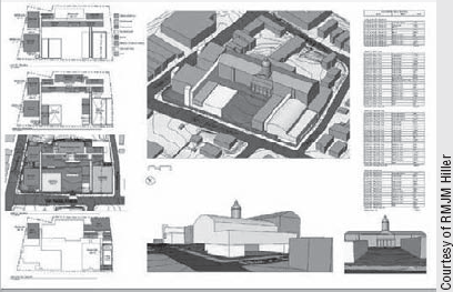
Feasibility Studies and Program Verification
You can take the massing study a step further and make feasibility studies to explore how to fit the client's program on the site and calculate the floor area ratio (FAR), mass floor area, and volume. With mode information added to the model, you can get better estimates about building cost, energy analysis, and aesthetics.
Three-dimensional digital massing studies allow architects to use advanced technologies and make physical prototypes for demonstration or testing purposes using the 3D printing services that are becoming more affordable. For many architects as well as owners, a physical model is still something they like to have in order to study the design.
Rapid prototyping is the automatic construction of physical objects using solid freeform fabrication. The first techniques for rapid prototyping became available in the 1980s and were used to produce models and prototype parts. Thanks to advances in technology and the increasing affordability of 3D printing, professionals in many fields now rely on rapid prototyping—architects to create models, industrial designers to make first-draft prototypes, and even artists to sculpt complex shapes for fine arts. The process of rapid prototyping takes virtual designs from a digital model, transforms them into virtual cross sections, and creates each cross section in physical space one after the next until the model is finished. This is often done by layering liquid and powdered material for each section and using glue or a laser; the material is fused together as shown here.
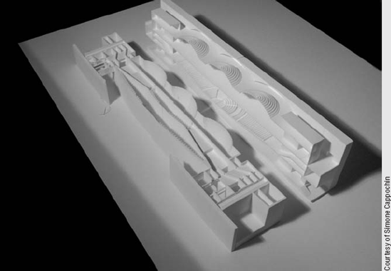
The most common file format for sending this data is .stl. The .stl export is not natively built in Revit—you can find a prototype for an .stl exporter for Revit on the Autodesk Labs site, http://labs.autodesk.com/utilities/revit_stl/.
Figure 8.4 shows a rapid prototype model of an unbuilt Louis Kahn building.
There are two ways to work with conceptual modeling tools in Revit—as in-place masses built directly in the project or as loadable families built using the conceptual mass family template. Each method offers slightly different behaviors, which can impact workflow. For example, building out a site context model, which is generally static, might make most sense to do in the project environment, whereas building multiple massing studies that can be swapped in and out of the site model is better handled with family instances. Anytime you have a massing shape that repeats and has some parametric variations in size, think of using a family.
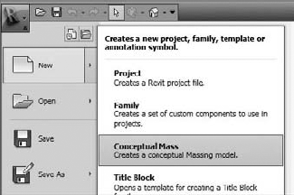
In order to create, study, analyze, and later convert a massing form into a building, you need to understand the available tools first; then we'll walk through a real exercise in which you can experience the entire workflow. If you're in a project already, the massing features can be found on the Massing & Site tab (Figure 8.5). You'll use this tab to create in-place masses, place masses, and model by face (apply Revit building objects to massing surfaces). To start a new conceptual mass family, use the Application Menu

The tools for creating masses in Revit are a bit different than those we discussed in Chapters 6 and 7, "Modeling Principles in Revit I and II." Rather than using explicit sketch-based tools (Solid Extrusion, Solid Blend, Solid Revolve, Solid Sweep, and Solid Swept Blend), you start with lines and then "create form" by selecting those lines. You can still make extrusions, sweeps, revolves, and blends, and you can also create lofts and surfaces now—but the creation method is a bit different in 2010 for making all of these forms. Once you have made a form, you can then freely manipulate it using interactive controls, temporary dimensions, and parametric dimensions. Click on any surface, edge, or vertex of a form, and a control will appear. Use this control to adjust the form. Figure 8.7 shows an edge being dragged with the control.
Once you've made a form, you can rationalize it by either dividing the surface and applying panels to the surface or applying walls, floors, and roofs to surfaces using the Model by Face tools and Mass Floors (Figure 8.8). Dividing a surface always takes place while editing the family, and modeling by face takes place when in the project environment.

There are two ways to create a mass element in the project environment—by making it directly in the project or by loading it into your project. Let's look at the tools that will help you do this.
- In-Place Mass tool

This method allows you to create a new mass element in the project. When you start this tool, a new tab, In-Place Mass, appears on the Ribbon. (We'll discuss this later in this chapter.)
- Place Mass tool

This method allows you to place a mass family or load a mass family from your library. To make a mass family, use the method explained earlier, by going to the Application Menu

- Show Mass tool

In order to support more fluid workflows, the Massing category has a special visibility feature built in that allows all massing to be either visible or not, throughout the entire project. This is a global toggle (similar to how Thin Lines mode works) that will keep you from having to manage mass visibility independently in every view. The toggle is located on the Massing & Site tab. We'll explain this now, as you'll get a warning message as soon as you start a new massing.
When you try to place or create a mass for the first time, you'll most likely get the following message, which conveys information about the visibility of mass elements:

This message can be disconcerting at first unless you understand what is going on. Visibility of mass elements can be controlled either via the Show Mass tool or through the Visibility/Graphic Overrides dialog box. The Show Mass control is a global on/off switch for massing that affects all views temporarily.
When you click the toggle button, all masses, in all views, will become visible. This is great for early massing studies, allowing you to move from view to view and see your mass without having to turn the category on or off in each view separately. When this mode is enabled, it does not affect the Visibility/Graphic Overrides state of your views. This massing toggle is a temporary view control and doesn't affect printed output.
To see the mass elements in specific views only, you should use the Visibility/Graphic Overrides settings for view control. Even when the Show Mass button is turned off, if you activate the Mass setting in the Visibility/Graphic Overrides dialog box, it will be visible in that view.
Keep in mind that to print and/or export massing, you need to turn on the Massing category using the Visibility/Graphic Overrides dialog box.
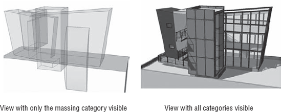
As you develop your design further by moving from the conceptual phase into the early design development phase, you will start creating the real building components (walls, floors, and roofs) by adding elements to the mass model. This will slowly but surely obscure the visibility of the massing form. A great way to maintain a view where only massing is visible is to create a 3D view where all categories are turned off except the Massing category. To do this, use the Visibility/Graphic Overrides dialog box. Be sure to duplicate a view when doing this, and name the view Massing or something appropriate. Figure 8.9 shows two views: one with only the Massing category visible and the other with all categories visible. This is handy when you want to make adjustments to the basic shapes that define the geometry (masses) without being distracted by the presence of the building elements.
You create massing forms using tools in the conceptual modeling environment. With these tools, you can quickly generate site plans and initial building shapes for early, formal design iterations. You can also divide surfaces and apply repeating components on the divided surface to explore more articulated designs.
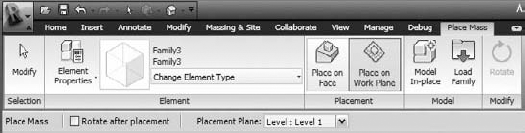
When you select the Model In-Place Mass tool from the Massing & Site tab, you're first prompted to name the mass you're about to create. Once you provide a name, the interface transforms and you will find yourself in a mass-creation mode, with a new set of tools (Figure 8.10). Using these tools, you proceed to create the massing form using combinations of solid and void forms.

The tools on this tab are specific to form making and surface rationalization and will be available until you click the Finish Mass button. You'll also notice that the other tabs are still available while modeling an in-place mass—click the tabs in the Ribbon to see what tools are enabled. Various other tools will be enabled or disabled depending on their relevance to massing tasks. For example, the Edit tools will still be accessible under the Modify tab, and Dimension will be available in the Annotate tab. Other tools, such as walls, floors, and roofs, will not be enabled. If you have modeled other building elements, these will not be editable while using in-place massing mode.

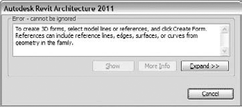
Figure 8.11. This warning message appears if you click Create Form without first selecting an input.
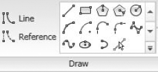
Use the tools in the Draw panel to create your initial lines (Figure 8.12). These should all be familiar tools—they allow you to draw lines, rectangles, polygons, circles, arc, splines, and ellipses. Note that there are two types of lines you can make: lines and references. Two differences between the two should be noted: first, lines will be "consumed" into a form when used to make a form, while reference lines will not. Second, reference lines can be used to host other elements, whereas lines cannot. For example, a family can be loaded into a conceptual mass and placed on a reference line, and if that reference line rotates or moves, the family will go along for the ride.
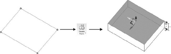
To get acquainted with this environment, start by drawing a simple rectangle, and click on the Create Form button in the ribbon to make a box. Note that if you de-select the lines before making the box, you simply re-select the lines and then click the Create Form button. You'll notice that selection in this environment will prefer chains of lines over individual lines when lines are connected. In other words, you will not need to press Tab to select a chain. When lines are selected, the contextual tab changes to Modify Lines. Clicking the Create Form button will then create a solid box, as shown in Figure 8.13.
You can make as many forms as you see fit for any given mass element. Everything you add in the mass editing session will create a single mass instance when you finish. Your decision to make each shape as a separate mass element will depend on what you need it to represent and how you intend to interact with it. For example, one mass element could have five boxes representing five buildings. Or, you could make five separate mass elements for each building. Do you want to move each building independently? Or, will you likely want to move all the buildings together as a single element? Let these kinds of questions guide your decision-making process.
Once you've made a form some controls will show up when a mass is selected. These controls will allow for some direct editing by dragging the triangular control grips on the form. You will get different controls depending on whether you are editing the form from the project context or the conceptual design mode. When you're in the project, you'll see blue triangles appear on masses when selected. These controls do not provide temporary dimensions, and the dragging will result in hard-to-predict numeric values (Figure 8.14). Rather than deal with these grips, it is easier to simply select the form and edit it in place. You'll get better interaction and more precise control with the arrow controls (Figure 8.15).
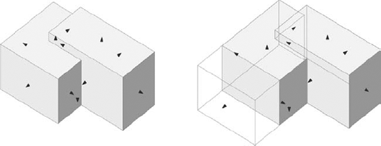
Figure 8.14. When a mass is selected, grips appear on the form. You can drag these and change the form.

Figure 8.15. For more precise editing and less visual noise, edit the form in place by selecting the surface, edge, or vertex you want to edit.
When you have a surface, edge, or vertex selected, you'll be able to use this control. Press the spacebar to change the orientation of the control to align with local geometry. This is useful if the geometry you are working on is not aligned to the global XYZ coordinates. Note that if the local geometry is aligned with the global XYZ axis, the control will not change appearance with the spacebar.
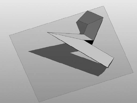
The conceptual tools support essential Boolean operations—such as cutting and joining of intersecting forms. It is important to note that massing forms can be solids or surfaces—something new to the 2010 release (Figure 8.16); however, surfaces cannot be used to cut into solids. We'll explore the range for form topologies later in the chapter.
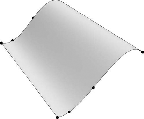
Figure 8.16. Surfaces, such as this loft, can be created in the conceptual massing environment; however, they cannot be joined to solids.
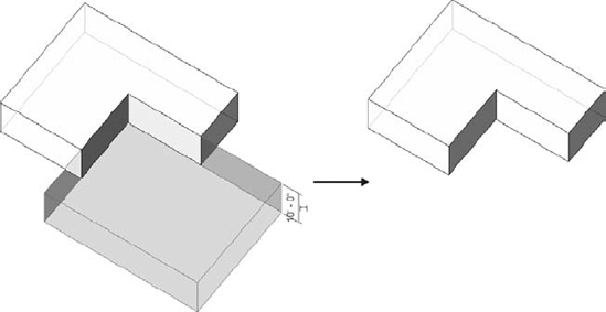
Any form can be either solid or void and can be changed from one state into another state at any time with the Create Form tool (Figure 8.17). Try making two boxes—one void and one solid—using the options in the Create Form pull-down. If the two forms intersect, the void will cut away geometry from the solid.


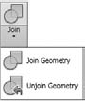
This tool joins solids to form one connected element. (Note that voids can't be joined together.) It merges the shapes (masses) into one, both graphically and as data (Figure 8.19). To use this tool, select the tool, and then select solids you want to join. Multiple solids can be joined together.
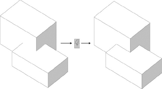
If you edit the position of one of the joined forms (by pressing the Tab key twice when over a joined geometry), the intersection (called the Boolean) instantly updates. If you move one of the joined forms outside the boundary of the other joined form so they no longer intersect, they will still maintain their Boolean relationship. You can see this by pressing the Tab key when your hover over an apparently disconnected form. Both forms will become selected (Figure 8.20). To remove the Boolean, use the Unjoin Geometry command in the Modify tab.

You can create your own mass families using the new Conceptual Massing Family Editor and load them later in any project. To create a mass family, you use a special family template called Mass.rft. Later in this chapter, we'll guide you through the creation of various mass forms.
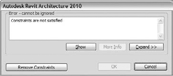
In the next section, "Understanding Form Making and Rationalization," we'll add parameters as we build forms. A feature unique to the new conceptual design environments is called "loose labeled dimensions." This sounds complicated, but it just means that the interaction with parametric dimensions has been loosened to allow more bidirectional behavior. Unlike in the standard Family Editor where a labeled dimension will prevent you from directly manipulating a form, in this environment, you are free to drag a form, and the labeled dimensions update on the fly. You will not be confronted with "Constraints Are Not Satisfied" warnings by dragging something with a labeled dimension, as you might see in the standard Family Editor.
We've talked about how to get started on a massing form and some likely workflows you'll encounter. Now we'll dig into how to actually create forms, and then we'll rationalize form using a surface division tool. In the following exercise we'll guide you through the creation of several types of forms that you can make in the conceptual modeling environment, including extrusions, lofts, sweeps, and revolves. (In the next chapter, "From Conceptual Mass to a Real Building," we'll explore creation of special panel components that can be hosted on a surface.) The result will be the mass shapes similar to those shown in Figure 8.21.
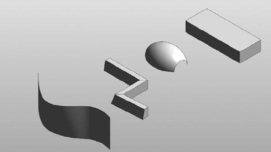
Figure 8.21. Basic forms that can be generated include lofted surfaces, sweeps, revolves, and extrusions.
First, when you're creating a new mass, it's essential to select the correct family template. In this case, you want to be sure to select Mass.rft or Metric Mass.rft—the default template if you use New
Choose Application Menu
The Family Editor opens with a 3D view. You'll see a base level and two reference planes in the view. The level sets a starting elevation plane, and the intersection of the reference planes define the origin of the family.
Using the Rectangle tool from the Draw panel, draw a rectangle on Level 1. This will be the default work plane, and it will highlight as you draw the rectangle.
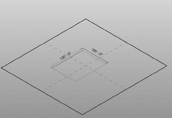
Click the Create Form tool. A box will appear, with a temporary dimension to the top of the box. Type in 100′ to set the height.


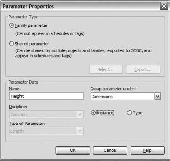
Using the Label dropdown list in the Options bar, add a parameter to the dimension—making it parametric.

In the Parameter Properties dialog box that opens, name the parameter Height, group it under Dimensions, make it an Instance parameter, and click OK.

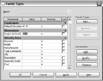
Set Height to 120′ and click OK. As you can see, the height can be whatever you want in the family environment, but without the parametric dimension, you'll have no way to change the height parametrically once the box is loaded into a project.
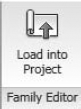
Open a new project using the Application Menu
Click to place the mass family, and then hit the Esc key twice to cancel the placement mode.
Using the 3D View tool in the Quick Access toolbar, open the default 3D view to see the placed mass. Change the view display to Shaded with Edges, and you'll see a semitransparent box.
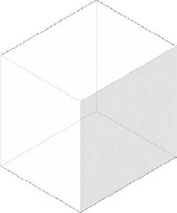
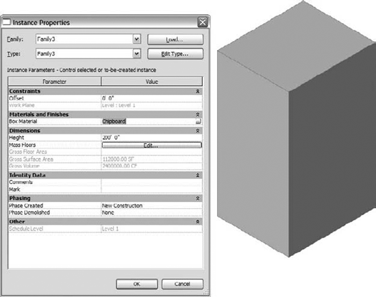
Select the mass and open the Instance Properties dialog box. Change the Height value to 200′ and click OK—you'll see the form update to the new height. Your mass box is now working parametrically.
You'll notice the material appears slightly transparent. This is because the material in the project has the same name as in the Conceptual Mass template, and materials in the project always trump those created in the Family Editor that have the same name. The reason for the semitransparent material is so you can visualize mass floors when they are added to a massing form, as shown in Figure 8.22.
To make the material parametric, follow these steps:
Go back to the box massing family.
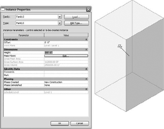
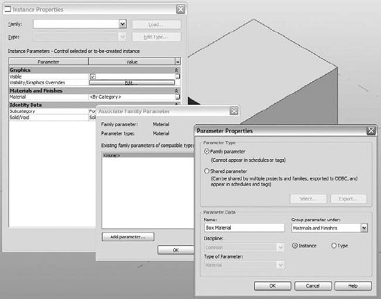
Select any part of the form and open the Instance Properties dialog box. Next to the Material parameter, click the small button at the far right. In the Associate Family Parameter dialog box that opens, click the button at the bottom, Add Parameter.
Create a new parameter named Box Material, group it under Materials and Finishes, and make it an Instance parameter.
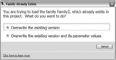
Load the family back into your project. You'll get a warning that the family already exists. Choose Overwrite the Existing Version.
Select the massing element, and open its Instance properties—you should see the new material parameter, Box Material. With this parameter you can now assign any material you want to the mass instance. In this example, we gave the mass a Chipboard material.

Now that you have made a parametric box with height and material parameters, let's see what other forms you can quickly generate with Revit's conceptual modeling tools.
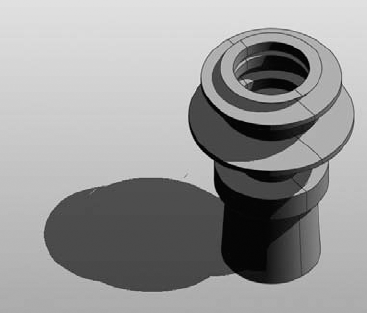
A revolve form (Figure 8.23) takes curves and revolves them around an axis. To make a revolve, you simply draw a line for your axis, draw lines to revolve around that axis, select the lines, and use the Create Form command. Revolves can be made from open or closed profiles. Let's try making one now.
Create a new conceptual mass family.
In the view draw a single straight-line segment—this will become the axis of rotation.
Draw an arc offset from the line segment—this is what will revolve around the axis.
Select the arc, and then make the radius dimension permanent using the Make Dimension Permanent toggle on the temporary dimension.
Add a parameter to the dimension named Radius.
From the Create tab, choose Aligned Dimension and dimension to the ends of the arc. Make this dimension parametric by adding a parameter to it named Length.

Select the arc and line, and then click the Create Form button. You will see a preview to two possible forms appear below the form: a revolve and a surface. Hover the cursor over the revolve preview and click on it—this will create a revolved form.

Select the top face of the form, and go to the Instance Parameters dialog box. Change End Angle to 180, and click OK. This will give you a half-revolve form.

Select any edge of the form and experiment with dragging the control arrows. You'll notice that the parameters update as you manipulate the form. At any point, you can open the Types dialog box on the Ribbon and enter exact numbers.

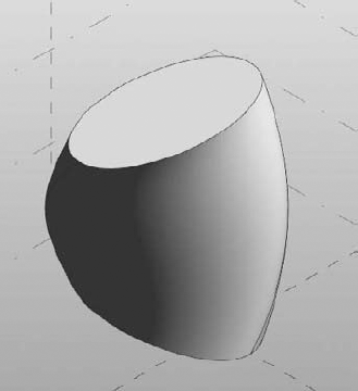
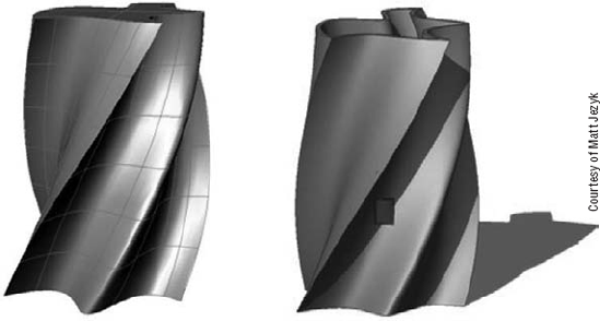
A lofted form (Figure 8.24) is a surface or solid that blends between two or more open or closed curves. For example, if you draw a series of splines on different levels, you can loft between the lines and create a surface. Likewise, you can loft between closed loops and even loft from a closed loop to a single line segment.

Let's make a lofted form now:
Open a new conceptual mass template.
Draw an ellipse on Level 1.
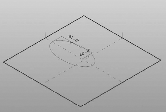
Select Level 1 and drag it up with the Ctrl key pressed—this will create a Level-2 copy. Set the height of the level to be 80′ using the temporary dimensions.
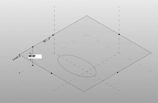
Select Level 2 and Ctrl+drag it to make a third level—set the height to be 80′ above Level 2.

Select the ellipse on Level 1 and press Ctrl+C to copy it to the clipboard.
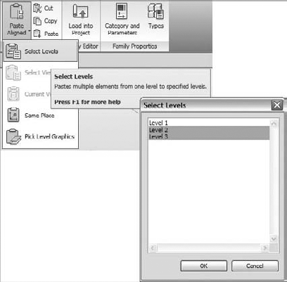
Using the Paste Aligned option from the Clipboard panel, choose Select Levels, and choose Level 2 and Level 3 by holding down the Ctrl key when selecting the levels.
Select the top ellipse and rotate it 90 degrees.
Select the middle ellipse and rotate it 45 degrees. Use the Options bar for quick numeric entry.

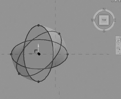
Use the View Cube to see the form from the top.


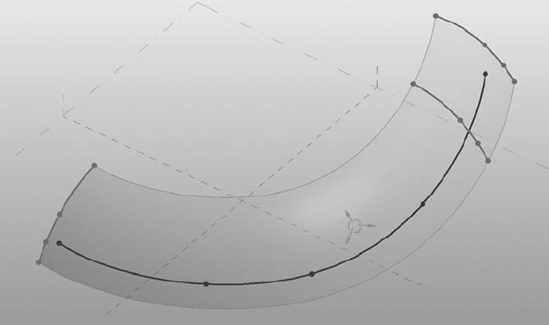
Sweeps are composed of a path and a profile that follows that path (Figure 8.25). A path can have multiple segments, so long as they are connected end to end. Profiles can be open or closed; however, if the path contains multiple segments, the profile must be closed.
Here's how to make a sweep.
Open a new conceptual mass family.

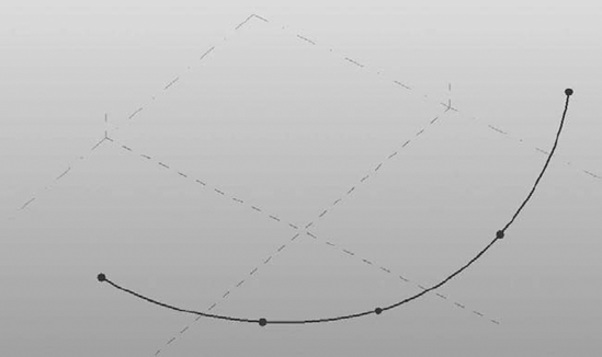

Select the reference point—this will set the active work plane to that of the point, which is perpendicular to the spline.
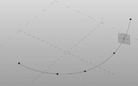
Draw another spline through points on the point you placed on the spline.
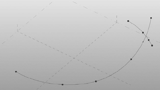
You can drag the reference point and see that it follows the spine it is hosted on, and by extension the spline you sketched on the point also follows. Select both splines and then click the Create Form button; a swept surface will be created.

Select the form and click the X-Ray tool to reveal the path and profile that are being swept:
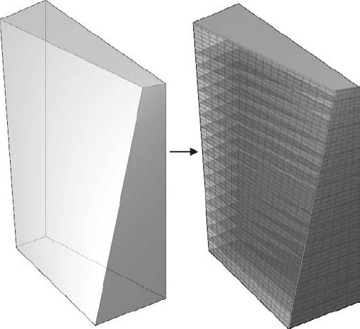
Once a form has been generated, it is often necessary to divide the form into regular intervals to better understand how a complex surface can actually be rationalized into buildable form (Figure 8.26). Once a surface has been divided, you can then begin to place real building components on that surface. These components begin to suggest an architectural articulation that goes beyond mere massing studies and also begin to suggest fenestration patterns, surface modulation, and surface variations.


The default division is a two-dimensional pattern that divides the surface evenly into 12 divisions in both U and V directions. U and V represent a way to show a surface as a mesh that follows the natural contours of a surface. You are probably familiar with XYZ coordinates; well, U and V are simply the letters in the alphabet directly before that. Start with a simple box, and select a surface to divide—click the Divide Surface button, and you will see the surface disappear and a UV grid appear. You can see a UV division on nonplanar surfaces, as shown in Figure 8.27.

Changing the UV division of the surface can be done a number of ways: using the Options bar, using the Instance Properties dialog box, or using the Configure UV Layout mode—accessible by clicking the icon that appears on the center of a divided surface when selected (Figure 8.28).
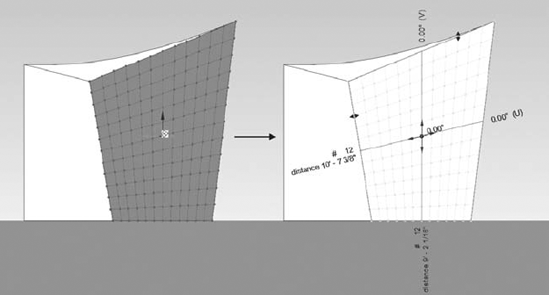
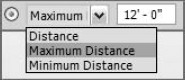
Divisions can be established using a fixed number or a fixed distance. If you want to start dividing a surface using more concrete sizes, change your division to fixed values. The fixed number will result in nonstandard numbers that change based on the surface. To change the division to use fixed distances, use the Options bar, as shown in Figure 8.29.
Once a surface has been divided, you can apply patterns to the surface. Revit ships with a fixed set of predefined patterns (Figure 8.30) that range from simple rectangles and triangles to more complex hex patterns and brick layouts. To apply a pattern, select the divided surface and use the type selector.

Patterns are two dimensional by default but can be swapped with 3D components on the fly. We will look at how to make a custom component family and get it onto a surface in the next chapter. Note that you cannot make custom patterns—you must choose a pattern from the preset list.
We walked through some examples of conceptual forms that can be created directly in Revit. Of course, Revit is not the only 3D modeler out there, and many people have become experts with tools such as AutoCAD, SketchUp, Rhinoceros, Maya, and 3ds Max, among others. All of these tools can still be used, and the geometry you create can be leveraged inside a mass instance or mass family. Importing CAD formats is supported in the conceptual design environment, and you can even divide surfaces from these files. You may want to use imported geometry in several scenarios:
You have users who are comfortable with 3D modeling tools such as those listed. They prefer to do the massing there and then use Revit's conceptual analysis capabilities as well as the Model by Face tools to turn the mass into a building
There are shapes and NURBS forms that Revit doesn't do easily (or at all), so you need to create the shape in another application. You need not import a whole building shape, as shown in Figure 8.31—it may be just a face of a shape that you'll need later to design a specific portion of a complex-shaped building, such as its roof
You can import individual masses (a complex shape, for example) or a fully developed massing study model. Regardless of what the import represents, the strategy is to never import it directly into the project file but to go through a family import:
If the geometry is an individual element that you're likely to reuse, open the Family Editor by opening a mass template, and create a new mass by importing the geometry
If you have a full study model, it's advisable to import it as an in-place mass family in the project (use the Create Mass tool and then choose Insert
We'll talk more in Chapter 9, "From Conceptual Mass to a Real Building," about how the behavior of the imported items depends on how they're imported, whether directly into the project, in a mass family, or in an in-place mass.
- Understand massing workflows.
Using generic forms, you can create early conceptual models and then use the mass to create the walls, floors, and roofs.
- Master It
You need to explore a design idea early on, in 3D, using abstract forms. How would you do this with Revit?
- Start a conceptual massing study.
In the project environment, you can make massing forms at any time. For generic forms that might appear in multiple projects, consider using the conceptual mass template and creating mass families.
- Master It
You've imported a 2D site plan, and now you need to start building a massing study model in the project. How would you approach this with Revit?
- Understand form making and rationalization.
You can make many types of form using Revit's form-making tools. You can then rationalize your form using the Divide Surface tool. Get familiar with how to go about creating forms, as it's different from in the standard Family Editor.
- Master It
You have made a form and want to edit it further. What tools can you use to make changes to the form?