Creating a BIM model requires modeling in 3D. This is very different from working with abstract 2D lines in order to represent your design. To work with Revit and be able to build a BIM model, you must understand how objects are constructed at various scales ranging from the building mass down to furniture assemblies. You need to know how various building elements interact and depend on each other, what materials they are made of, and how they are constructed and assembled. To this end, Revit provides a set of tools that enable you to model all the elements that go into the model. Understanding the principles of modeling in the context of Revit is essential to your success as you move deeper into building information modeling.
This chapter is the second part of a description of the basic modeling principles that support the design process in Revit. In this chapter, you'll learn to:
Understand the principles of modeling in Revit
Model with five basic forms
Combine solids and voids to create complex and intriguing forms
Revit is much more than a 3D modeler. It was designed specifically for architects and has behavioral rules built into many of the architectural elements that make up the model. For example, walls are usually vertically oriented rectangular shapes; floors and ceilings are horizontal shapes with constant thickness. These major building elements use 2D boundary lines to generate 3D geometry, as these types of elements tend to have a consistent thickness. This is one of Revit's major differences when compared to a generic modeler that lets you model anything, any way you like. In essence, with Revit the type of element you are modeling will present a tailored set of creation tools. This approach to software tools becomes more apparent in Revit 2010, with the introduction of a new set of conceptual modeling tools designed to support free-form modeling in the early phases of design development. We'll delve into more specific methods of modeling throughout this chapter.
Revit provides specialized tools depending on the element you are creating. For example, you draw a wall by defining its start and end points, which will determine its position and length, while the width and height are determined by the instance and type properties of the wall. The wall becomes a 3D element immediately with each click of the mouse. Roofs, floors, and ceilings, on the other hand, require you to enter a 2D drawing mode to define the boundary shape. Their thickness is defined in the type properties. To create conceptual models, you start by drawing lines, and then select them to make 3D forms. Once you've made a form, you can then modify it directly using interactive controls on edges, faces, and vertices. We'll dig into the specifics of this toolset in the next chapter.
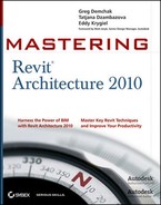
Once the envelope of the building has been established (walls, floors, and roofs), you progressively add more elements—windows, doors, furniture, plumbing fixtures, and so on—to the model. These building components rarely depend on the context of the building and are usually manufactured offsite at a factory in real life. Somewhat similarly, in Revit many components are predefined and saved in a library for use across multiple projects. These loadable components are all created in the Family Editor using a combination of simple geometric forms that can be associated with parametrically driven dimensions and materiality. For example, a chair can be created with a combination of sweeps, blends, extrusions, and revolves. The same applies to a light fixture, a bench, a plumbing fixture—you name it. Figure 7.1 shows samples of standard "loadable" family types.
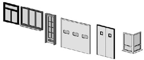
The Family Editor allows you to create components of any flavor. In some cases, the flexibility of the Family Editor modeling tools can be useful in the context of your project. When you want to create a custom design feature that is tightly related to the context of the building or the landscape around it (such as an entrance canopy or a reception desk in a welcome area), you'll need a robust set of tools that are not part of the basic wall, floor, and roof tools. To access the full range of Family Editor modeling tools in a project file, use the Model In-Place tool located in the Component drop-down on the Home tab (see Figure 7.2).
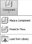
You can use the same features of the Family Editor to create your geometry. Figure 7.3 shows a fireplace built as an in-place model.
Another workflow where free-form modeling comes into play is at the early stages of conceptual design, where massing studies are explored. With massing, the tools need to be flexible and not constrained to a specific use case. In Revit, these mass forms are created with the Massing tools as combinations of various geometric shapes. In Revit 2010, when making massing forms using the conceptual design tools, the interaction with form is intended to support free-form creation and direct manipulation of forms. You do not enter a "sketch mode," but rather edit forms directly. Figure 7.4 shows a massing study using Revit's form-making tools.

When creating standard components, there are five basic form-making options in Revit. With these techniques you can create a variety of shapes for various scales of design. By combining forms and using forms as subtractive elements, you can model nearly anything in Revit. The five primary modeling techniques used for making components in Revit are:
Extrusions
Revolves
Sweeps
Blends
Swept Blends
These are accessible from the Family Editor when you're creating Solid or Void forms, and are also available when you're making in-place family components within the Project environment (Figure 7.5).
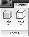
You can choose to create either solids or voids when making 3D forms. Selecting Solid Form or Void Form from any of these toolbars displays the options shown in Figure 7.6.

An extrusion, the simplest of all modeling transformations, is derived from a 2D loop (a closed chain or chains of line segments) drawn in a plane that has a thickness value. The thickness is always perpendicular to the work plane of the 2D lines (see Figure 7.7).

The element properties of an extrusion allow you to set the thickness of the extrusion as well as an offset from the work plane it was drawn on.
- Extrusion Start
This defines where the extrusion starts and has a default of 0, but it can have any positive or negative value. The effects of this parameter are shown in Figure 7.8.
- Extrusion End
This parameter defines the end of the extrusion relative to the work plane. This value can be positive or negative. The default is set to 1″−02 (250mm). The total thickness of an extrusion is the difference between the extrusion end and extrusion start.
When an extruded element is selected, check the contextual tab and the Options bar for relevant options.

- Edit Extrusion
This button takes you back to the 2D editing mode so that you can make changes to the underlying shape. Once you have changed the shape, don't forget to click Finish Extrusion on the Ribbon.
- Depth
Depth defines the value of the extrusion thickness. This value can be positive or negative. With vertical extrusions, the depth actually is the height of the extrusion.
- Visibility Settings
Visibility Settings define in which view types or levels of detail the extrusion will be visible. Figure 7.9 shows that the selected extrusion will be visible only in plan and reflected ceiling plan views, and only in medium and fine levels of detail. Setting the appropriate Display and Detail Level will improve printing, exporting, and overall graphic performance.
- Edit Work Plane
This button allows you to change the work plane of the extrusion. You can only set a new work plane if it is parallel to the existing work plane of the extrusion.
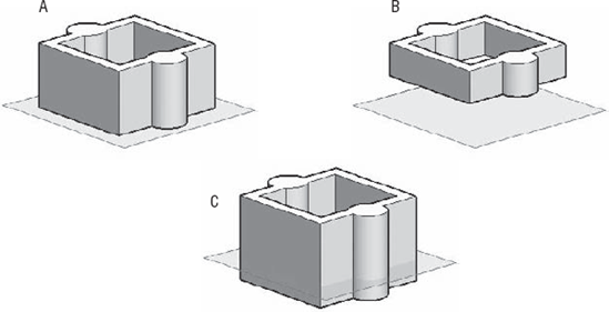

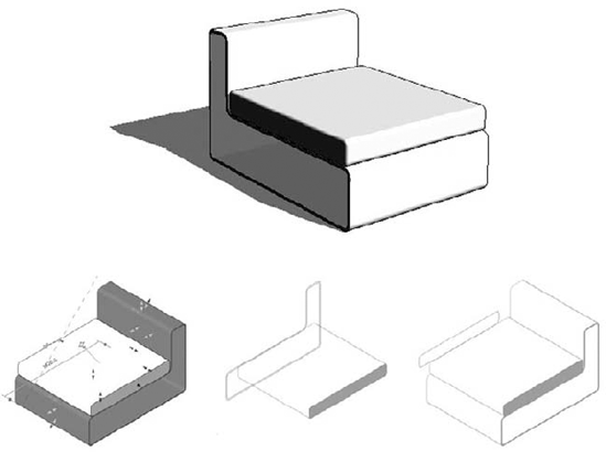
Figure 7.10 demonstrates how a furniture element can be constructed from two extrusions that create the entire shape.
Directions in a Reference Plane
The direction in which you draw a reference plane determines which way is positive and which way is negative.
These images demonstrate in plan view how the direction in which the reference plane was drawn affects the direction of the extrusion.
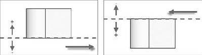
Because it is difficult to remember which way you drew each reference plane, we suggest that you name each reference plane you create. If you do that, you will see the name of the reference plane when it is selected, and the name is always placed at the end of the direction in which it was drawn.
When you use the face of an element as a work plane (rather than a reference plane), as shown in Figure 7.11, the direction of the extrusion will depend on whether you are making it a solid or a void shape.

When you sketch a shape that is going to be a void, the void extrudes positively toward the interior of the object that you used to define the work plane.
When you add a solid shape, the shape extrudes positively away from the exterior of the object face, as shown in Figure 7.12.

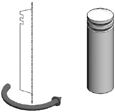
A revolve takes a 2D profile and rotates it around an axis. A revolve is composed of two elements: a 2D profile (think of this as a cross section) that will define the surface once it is revolved, and an axis that the profile revolves around. As with extrusions, the profile must be a closed loop of lines for the revolve to be valid. The bollard shown in Figure 7.13 is an example of a revolve form.
By default, a revolve follows a full 360-degree path. In the element properties of a revolve, you can adjust this angle so that the profile will appear open, as shown in Figure 7.14. The parameters for the revolve will let you determine the start and end angles:
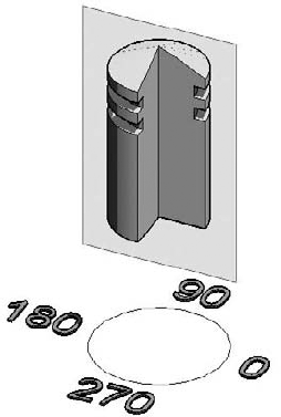
- End Angle
The end angle positions the profile relative to the work plane of the end of the revolution. Figure 7.14 shows a revolve with an end angle set to 270 degrees.
- Start Angle
The start angle positions the profile relative to the work plane at the beginning of the revolution. By setting the start angle to a value other than 0, you can get shapes like that shown in Figure 7.15.

When you select a revolve form, you'll see options similar to those available for an extrusion.
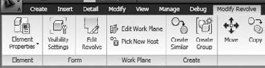
These are similar to the options available when selecting other modeling forms. You can change the 2D boundary that you used to execute the revolution with, set the visibility, edit the work plane, or re-host the form to another plane.
To understand how sketches create revolve shapes, we will look at three different results based on three different types of sketches. Figure 7.16 shows a standard revolve made out of one closed loop of lines; Figure 7.17 shows a revolve made out of two closed loops, where one loop is a subtractive element; and Figure 7.18 shows another revolve with two closed loops, where each loop is an additive element.
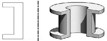
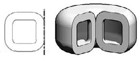
Figure 7.17. In this example, the two closed loops of lines are placed one inside the other. Following the principle of sketch-based design, the inner loop creates a hole in the first loop.

Figure 7.18. The two loops are independent of one another and thus the resulting revolution creates two solid shapes.
A revolve can be composed of multiple closed loops to define the profile lines. Keep in mind that a profile must not intersect another profile; if it does, it will fail, and Revit will warn you when you try to finish the revolve. Depending on the positioning of the different profile loops, you can achieve different results, as shown in Figures 7.17 and 7.18.
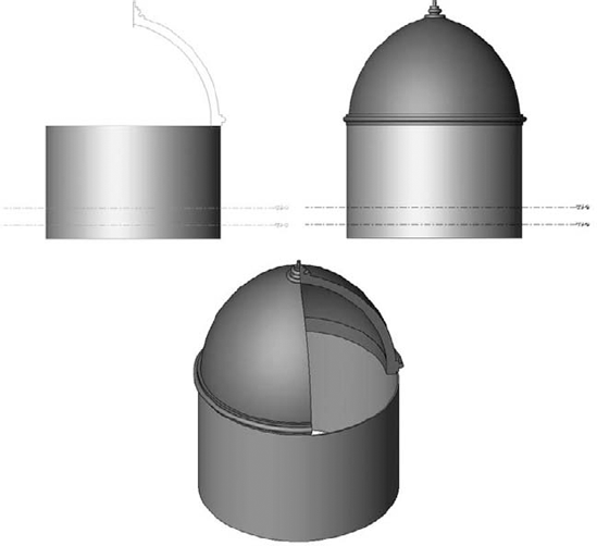
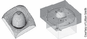
A common example of a revolve form appears in Figure 7.19. The profile defines the cross section of a dome (cupola) roof. By rotating this profile around the center axis, we can generate a dome form.
Another example of a revolve is this doorknob (Figure 7.20), where the cross section is drawn and then revolved around an axis.

A sweep is conceptually similar to an extrusion, but you must define a path for the extrusion profile to follow. The resulting form is generated by sweeping the profile along path segments. The profile is always swept perpendicular to the path segment it follows.
A sweep is defined by two sets of lines: the path, and the profile that you sweep along the path. The path can be drawn on any work plane, and the profile will always be drawn perpendicular to the path. The first segment of the path you draw determines the default work plane for the profile lines. To change the default location of the profile sketch plane, delete the line segment of the path that hosts it; the profile plane will jump to the next available line segment in the path. Figure 7.21 shows a swept form, along with the path and profile used to create it.

Figure 7.21. Example of a sweep. The dashed rectangle is the profile plane, which is always perpendicular to the path.

With this method, you create a dependency between the swept element and the object that you selected for edges to define the path. Thus, when the geometry of the referenced object changes, so too will the swept element. We strongly recommend working in a 3D view when using this method, as it will make it easier to understand the relationships and effects of changing geometry (Figure 7.22).

A profile can be created using one of two methods: by drawing the profile directly or by using a loaded, predefined profile. These options are shown in the Ribbon when defining the profile for the sweep. The default, By Sketch, lets you draw the profile using standard draw tools. Click the Edit Profile button to bring up the Draw/Pick Gallery and start drawing lines. Once a profile has been loaded, it will show up in the Profile drop-down list.
This method is applicable in cases where you need to sweep the same profile on many paths. For example, you would first create a 2D profile family using the Profile (imperial) or M_Profile (metric) template. The profile has to be a closed loop of lines. Save the profile on your hard drive and then load it in your project or family.
Figure 7.23 shows the drop-down list and the Edit Profile and Load Profile buttons.
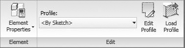
Figure 7.23. The default method for creating profiles is by sketching. You can also load premade profiles and use those.
If you use a loaded profile, you are given controls to position the profile relative to the X and Y axes (see Figure 7.24). These values are distances from the point of insertion of the profile (the intersection of the two reference planes in the Family Editor) and the point of reference of the profile and the path (the green cross). The values are editable in the Options bar, and will update if you move the profile interactively as well.
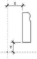
Figure 7.24. Offsetting the profile from the point of reference of the path. In this profile, the crossing of the references in the Family Editor was set to the lower-left corner of the profile. Thus, the offset values start from that point.
You can rotate the loaded profile by adding a value under the Angle option (see Figure 7.25). The Flip button mirrors the profile, if you need it. Click the Apply button on the Options bar to finish placing the profile.

Once a sweep is created, you can always change the values that are available in the Element Properties dialog box of the sweep, shown here:

The advantage to using premade profiles is enormous. Figure 7.26 illustrates a concrete example of a sunshading family that needs to be edited.

If you had drawn your profile manually and then used the Copy Multiple command to repeat the shade, you would need to change each shade separately to apply a new profile. However, if you had drawn the shape as a loadable profile family and loaded it into the family, you would only need to change the profile family once and reload it. All instances of the profile will update automatically when reloaded.
Here are some real-life scenarios in which the Sweep tool is very handy. We'll let the pictures do most of the talking.
First consider the modern shower fixture in the bathroom shown here:
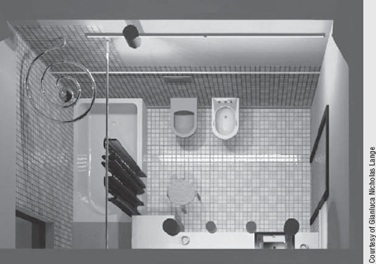
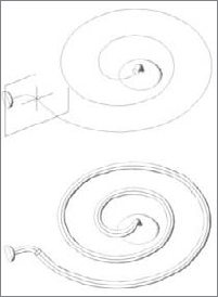
This design was created as a simple sweep on a circular path:
The architectural example shown next demonstrates another use of sweeps: to create a highly specific wall shape. The retaining wall was created as an in-place wall using the Create function and the Sweep method.

The Trajectory Segmentation parameter (see Figure 7.27) provides a way to segment smooth arcs into linear segments. This can be useful when you're rationalizing a form into planar, constructible elements.
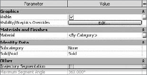
When the option is checked, it makes the parameter Maximum Segment Angle active. The value you set defines the maximum value of the angle between two segments of the arc. The smaller that value, the higher the number of linear segments that will replace the arc. Figure 7.28 shows the effects of this parameter.

A blend creates a form by connecting two different 2D shapes on two different planes along a linear path (see Figure 7.29). The distance between the two shapes—the base and top—is what defines the depth of the blend. The two shapes for the top and base of the blend do not need to be the same shape or have the same number of segments. Revit can even blend arcs into linear segments.

When the top and base shapes are the same, the resulting form will look exactly like an extrusion or sweep along a single, linear segment. You can think of a blend as an extrusion with two sketches—one for the base, and one for the top.
The instance properties of a blend resemble those of an extrusion. You can set the blend depth as well as the offset from the work planes on which the shapes are drawn:
- First End
This defines the offset of the base shape relative to its work plane. This value can be negative or positive. The default value is set to 0.
- Second End
This defines the offset of the top shape relative to the work plane on which the blend is drawn. This value can be positive or negative. The default is set to 1′−0″ (250mm).
The total depth of the blend is the resulting value between the first end and the second end.
When a blended element is selected, look to the Modify Blend tab, where you'll be able to reedit the base and top, change the work plane, and re-host the blend:
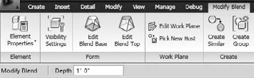
As you can see, these are the same as the options you had for extrusions, with the addition of two other features that take you to the sketch of the base or top of the blend:
- Edit Blend Base
This allows you to enter boundary edit mode, where you can modify the top boundary.
- Edit Blend Top
This allows you to enter boundary edit mode, where you can modify the base boundary.
Whenever you select one of those two options, the Ribbon will update as shown in Figure 7.30. Click Finish Blend to complete the blend.
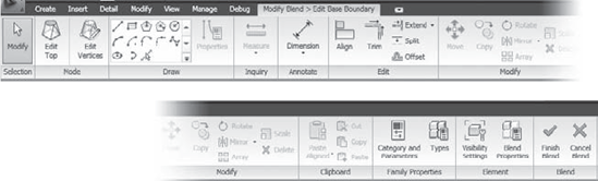
When creating blends, the boundaries are drawn on a single work plane; this means that the two shapes will always be parallel to one another.
The Vertex Connect tool is specific to blends, and it shows up in the Ribbon when you're editing the blend boundary lines. This tool allows you to set the connection between the vertices that the two shapes have. Manipulating the vertices alters results in the final blend.

There are two different things you can do here:
- Twisting
After selecting the Edit Vertices tool, a new contextual tab will appear with the options Twist Right, Twist Left, and Reset, and the ability to edit the controls at either the base or top.

These options control the number of twists between the two shapes. In Figure 7.31, image A shows a basic blend between two 45°-oriented square shapes. Image B shows one additional twist, and image C shows yet another twist.
- Editing Vertices
This is another way to affect the blend in order to arrive at alternative shapes. By clicking one of the open blue circle controls that appear when you first select the Edit Vertices tool, you can change the direction of the vertices by clicking on the control. Once you change the connection point, the circle will be filled in solid blue, and a line will be drawn showing a preview of the connection from one vertex to another. Revit connects the vertices from the base shape to the top shape in an automated way with each click. But each of the vertices has an option to be connected to the top vertex that lies to the right of it, or to the left, or both. The example shown in Figure 7.32 demonstrates how the same blend with the same base, top, and depth all look different depending on the vertex connections.
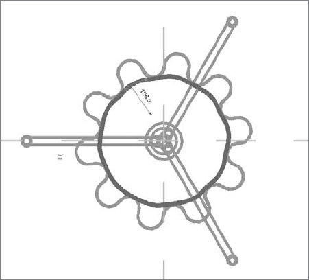
When the base shape of a blend has the same number of vertices as the top shape, the results are pretty much predictable. But often the number is not the same and you may not get the results you expect or desire. Here's a tip to consider when working with more complex blends: if one of the shapes is a circle, you might want to break it up into segments to get additional vertex points so that you arrive at a shape you need, as shown in Figures 7.33 and 7.34.

Figure 7.31. Various looks for the same element depending on the number of vertex connections or twists: the form shown can be either a tower shape or a table leg.


Figure 7.33. A standard blend you will often see, with the base shape a square and the top shape a circle.

Figure 7.34. The same shapes with the circle split into four segments to add three more vertices. In example A, the vertex points are orthogonal; in B, they are rotated 45 degrees. Note the difference in the results.
Creating a Lamp with Blends and Sweeps
A real-world application of blends and sweeps can be seen in the Revit lamp family illustrated here:

The shade is constructed using a blend between a segmented circle for the top (A) and a more complex series of arcs for the base (B).

The top boundary has been divided into many segments to match the number of vertices of the base. This file can be found in the Chapter 7 folder on the book's companion web page if you want to explore it some more on your own (PS Lamp.rfa).
The legs of this lamp were made using sweeps. A void extrusion was used to cut the bottom of the legs horizontally so that the lamp sits flat on the floor.

The shapes in Figure 7.35 are inspired by the lamps of sculptor and designer Isamu Noguchi, but as you can imagine, they could just as easily represent a lamp, a column, or the shape of an entire building. They are constructed as simple combinations of connected blends.

The blend boundaries cannot contain more than one loop of closed lines. If your intention is to create something like the lampshade shown in Figure 7.36, you need to add a void, or use a revolve. If you try to make such a shape using multiple loops, Revit will give you a warning message telling you that "more than one loop is not allowed."

Figure 7.36. This blend sketch with multiple loops is not allowed and would generate a warning message.
To obtain the result needed, you need to first create a solid blend and then a second one, done with a void that has a smaller radius, as shown in Figure 7.37.

The swept blend is a combination of a single-segment sweep with a blend. The principles for creating a swept blend follow from the sweep and blend workflow. With a blend, you have no control over the path: it is always perpendicular to the sketch plane. With the swept blend, you can create arc paths for the profiles to blend along. Examples of this include a roof or roof segment with a shape that changes over a nonstraight path, an elbow pipe that changes diameter between the two ends, funky furniture shapes or parts, and walls beneath curved stairs. Note that a swept blend can only contain a single line segment for the path. If you draw more than a single segment, Revit will issue this warning: "More than one curve not allowed."

Many complex shapes go beyond the basic form-making techniques we just explored. Designs often require a combination of forms that are both additive and subtractive. To accommodate richer modeling, Revit approaches this problem by allowing any form to be solid or void. Solids are positive, physical elements, and voids are invisible, cutting elements that remove form from solids.

Voids can be used in many ways to arrive at some surprising geometric forms. Think of a void as a way to carve away from a solid chunk of clay. You can truly sculpt with this tool!
In Figure 7.38, complex vaults have been created out of a solid pentagonal extrusion and half-circle void extrusions are cutting through it.

The basic shape of the table legs shown in Figure 7.39 is a simple blend. A plow shape is used at the base, and a triangular shape is defined for the top (A). Then a simple curved shaped void extrusion is used to carve out the blend (B). The result is an interesting shape that is far more complex than what you'd expect to be able to do with the four basic modeling forms (C-D).

A shape like the one shown in Figure 7.40 could be created using two revolved shapes and then cut off using a void square around the edges.
Where Can You Go from Here?
Mastering the modeling techniques in Revit and understanding the power of parametric relationships will open doors to some powerful modeling skills. In order to construct custom components, you'll need to become familiar with the toolset, and once you do, you'll be able to model nearly anything you can imagine. We've walked through the basic form-making tools for generating components. In the next chapter, "Concept Massing Study," we'll get into the new form-making tools that were added to Revit 2010 for making building mass forms. You'll see that making complex building forms in Revit is no longer science fiction, but right at your fingertips!

- Understand the principles of modeling in Revit.
Understanding how to use Revit's modeling tools is an important part of project documentation. Knowing which modeling tools to use when will aid not only in project visualization but also in documentation, scheduling, and rendering.
- Master It
There are many unique design elements in any project. Know when to use the appropriate modeling tools at the right times. What tool in Revit might you use to model the following elements?
Reception counter
Entry canopy
A lampshade
Custom furnishings
- Model with five basic forms.
These tools are at the root of practically all form modeling.
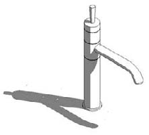
- Master It
Having learned the basics of Revit's form-making tools, how would you build this faucet designed by Philippe Starck?
- Master It
In some cases, a form uses multiple sketch lines to generate its form. What form-making tools in Revit use more than one set of 2D sketches to generate the form?
- Combine solids and voids to create complex and intriguing forms.
Revit's five basic forms can be expressed as either positive space (solids) or negative space (voids).
- Master It
To make more complex forms, both solids and voids can be used. Think of a case where the using voids as a subtractive element makes sense.