Revit supports workflows where multiple design options need to be explored, evaluated, and presented. This type of workflow is an integral part of developing and iterating a design solution. With Revit's design options, you can use the same integrated building model to create a range of variations on a design at scales that range from entire façade studies down to kitchen layouts.
In this chapter you'll learn to:
Use Revit design options
Decide on a design solution
Use design options with parametric design
Revit provides a set of tools for developing multiple design iterations in the context of one project. You can use these tools to explore alternative designs without having to keep saving multiple independent versions of your model as you move in different directions. With Revit's design options, you create, evaluate, and mock up a wide range of options in the context of your project file. You're free to investigate multiple roof configurations or different entry canopies, explore various furniture and office layouts and stairs—quite literally anything that can be modeled. Figure 10.1 shows an example of the same building model with two different entry canopies. Each canopy belongs to a separate design option that can be displayed or hidden in any view. This lets you create views that show each option so the two designs can be evaluated against each other.

Design options work in the following manner. First, you have a main model, which includes all the elements you've modeled that are fixed and not affected by the options you want to explore. The main model can be thought of as a backdrop or stage on which different options play. Elements in the main model are always visible by default whereas design options—such as different furnishings for the interior or different canopies over an entrance—come and go, appearing and disappearing depending on what you're editing. Put another way, the main model includes everything else that's not in the options.
You can make as many options as you need—there is no limit. You can create views for each option that only show that option displayed against the main model, and thus be able to place these views on a sheet in order to compare and contrast your designs. You can then present them to a client, to the project architect, or to other stakeholders in the design process. Once a design option has been settled on, you accept it as the primary design solution going forward by adding it back to the main model. Doing so deletes all elements in the design option that you won't use going forward. That is, some elements become embedded in the architecture, while others disappear forever.
To access the design option toolset, switch to the Manage tab and select Design Options from the Design Options panel.

In a new file that has no design options yet, by default only one button (Design Options) is enabled. That button launches the Design Options dialog box, where you create, manage, and edit all the design options in a project. We'll cover the other buttons in the next few sections.
Creating a design option doesn't create anything at first—it simply sets up the work environment so you can begin making various designs using the feature.
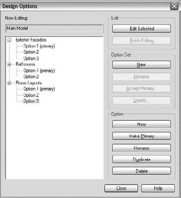
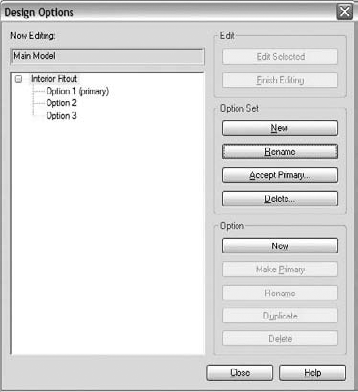
In Revit, every design option belongs to a design option set, which is a way of structuring the design options into clusters to aid your workflow. For example, a project may have three design options for an exterior façade, two options for a bathroom configuration, and three options for room and furniture layout. Revit allows you to have several sets—one for each major type of option you're exploring. You may have a design option set called Exterior Façades, one called Bathrooms, and another called Room Layout. In each set, you can have as many options as you need for the design in question. This hierarchy is structured as a tree interface in the Design Options dialog box, as shown in Figure 10.2. Each option set is shown in a top-level node of the tree, and each design option is shown as a child of a set.
As you can see in Figure 10.2, there is always a primary option in each set. It is designated by the "(primary)" suffix. This makes that option always visible by default in any view unless overridden. You can change the default primary option by selecting any other option in that Design Set in the Design Options dialog box and clicking the Make Primary button. In the views, the new primary option will then be visible by default, hiding the previously defined primary option.
When you reach a point in your design where you'd like to explore multiple design solutions, it's time to start creating option sets. Think about how you'd describe the option—Façade Studies, for example—and name your option set accordingly. Add at least two options to the set—more, if you think you'll be exploring more than two options. You don't have to define all the options in the beginning; you can always come back and add or remove options if needed.
Creating new design option sets is straightforward. Click the New button in the Option Set zone in the Design Options dialog box, and a new set is created. To give the set a unique name, select it in the tree and click the Rename button from the Option Set zone. Adding new options within the set follows the same pattern: use the New button in the Options zone, and then give the set a name.
You can delete design sets and options at any time. Deleting a design option effectively deletes any elements added to a design variation you've made using that design option. Deleting a design options set deletes all options in that set. These are drastic decisions, so be wary of deleting anything before you're sure you are ready to do so. Deleting a design option will also delete any views that you have set up specific to those design options. In both cases, Revit will warn you before the views and option sets are removed. The same effect is achieved when you click the Accept Primary button—all other options in that set are deleted.
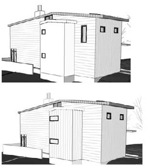
Once you've formally established design option sets and design options, you can do a number of things depending on the scope of your options. You can add elements from the main model into each option if you want to experiment with variations of the element. This way, you can explore different expressions of the same object without adding new elements. For example, if you want to show two roofs with the same footprint but different slopes, this method of adding the roof into each design option will work nicely. Once the roof is added to each option, you edit the option first, then edit the roof slope. The roof is essentially a copy and can be edited independently in each option (Figure 10.3).
Another way to work with options is to start editing the option directly, without first adding elements to the option. This approach works well if you have a design idea but don't want to add it to the main model just yet. When you begin editing an option, the main model grays out, and any new element you add is added to the active design option. For example, let's say you haven't yet designed the entry canopy for your model, and you want to experiment with some different ideas. Start editing the option, and you can then model whatever you want. The main model is still visible for reference, but it won't be editable.
You can use both methods in combination as well. For example, you might add a wall from the main model to two options and in each option add new, but different, window types to the wall. You'd use the Add to Set button to put the wall into both options, and then you'd edit each option to add the new windows.
To edit a design option, expand the list of available options from the Design Options panel and choose the option you want to edit. That option will become active and you will enter a special edit mode in which anything you create will be added to the active design option automatically. Use this method if you're starting from a blank slate and laying out several options for furniture layout or exterior shading devices, like those shown in Figure 10.5.

When you're adding elements to design options, keep the following basic rules in mind:
Host-based elements that cut the host (such as windows or doors) need to be included with the host when you make design options, meaning both the host and the insert have to be a part of the same option. You cannot have the host be a main model but make the inserts an option.
Inserts are automatically copied with the host when you add hosts to design options. Using our example of a wall with a window in it, if you add the wall into a design option the window is automatically added as well.
By the same token, if you're editing an option and try to place a window or door into a wall that's not included in the option, you'll get a warning:
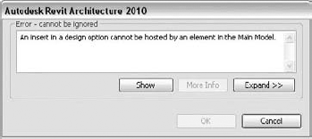
You need to add that wall to your design option if you want to place inserts in the wall. Host-based elements that do not cut their hosts can reside in different design options without the host. For example, a wall-hosted sink can reside in a different design option than the wall on which it's mounted (which resides in the main model), but a window that cuts a wall can't.
When you're adding curtain walls from the main model to a design option, the grids, mullions, and panels are automatically added for you.
When you're adding a roof to a design option, you should include all walls that attach to that roof. Otherwise, you won't be able to attach walls to the roofs in your design options.
When you create groups or arrays within a design option, selected elements must be in the active option.
Because the elements in a design option can't be selected from the main model, you'll need to use this feature to edit elements belonging to an option or activate a design option. For example, if you add all your exterior walls to design options in the Exterior Façades option set, the walls won't highlight or be selectable unless you're editing one of the design options. If you add elements to a secondary option, they won't be visible by default in the main model.
To start experimenting with design variations, after you create your design options you can edit them. To do so, use the drop-down menu in the Design Options panel and choose the option you want to edit (Figure 10.6). Alternatively, open the Design Option dialog box by clicking the Design Options button, select an option in the zone on the left, and click the Edit Selected button in the Edit zone on the right side of the dialog box.
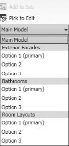
The moment you select an option to edit, the main model grays out and becomes unselectable. This allows you to modify the elements in the design option without worrying that you'll mess up other parts of the model. Any element created while in the design option's Edit mode is automatically added to that option. For example, if you're editing Option 2 of an Exterior Façade set and you insert new windows in a wall in that option, the windows are added to the design option—they aren't added to the main model.
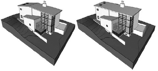
Using design options, we added the exterior skin of a building to two options in an option set. By creating a new wall type with different materials, we easily exchanged one wall type for another in each option. Once the wall types were swapped in each option, we duplicated the perspective view showing the exterior skin and changed it to show each of the options (spandrel glass in the one on the left, wood in the one on the right) using the Visibility/Graphic Overrides dialog box. To make the northeast perspectives easy to find in any list, we assigned the views meaningful names: Glass NE and Wood NE.

Take the example in Figure 10.4 of two views showing different roof options. In each view, to start editing the option choose Pick to Edit, select the roof, and start editing the roof. You don't have to think about the name of the option.
To visualize different design options and have them represented in separate views that you can drop on a sheet, you need to create a new view that displays the desired option. These usually are duplicated views of the same view for which you want to show different options. To do this, right-click any view in the Project Browser, choose Duplicate, and give the view a name that indicates which design option it represents. Then adjust the visibility/graphic overrides settings of that view to show the desired design option.
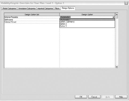
As you can see in Figure 10.7, once you've created option sets and design options, a new Design Option tab appears in the Visibility/Graphic Overrides dialog box of all views. The default visibility setting is Automatic, which means that the option displayed will be the primary option and the main model. However, using the drop-down menu under Design Option, you can override this setting and show any of your other options.
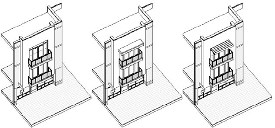
In Figure 10.8, three options are shown for a building façade: Option 1 has no canopy over the third-floor deck, Option 2 has a solid canopy, and Option 3 has a louvered canopy. All three options exist in the same model and can be visualized next to one another by duplicating the view and changing the design option in the visibility/graphic overrides of the view. By duplicating views and changing the default design option visibility, it's easy to compare options and even place the views on sheets for printing.
After many meetings and discussions, there will be a moment when you will decide which option is the final one—the one to build. Keeping unused and out-of-date options in the project needlessly inflates the file size and adds unwanted complexity. Revit will let you, with one click, choose the option that will become a part of the main model and get rid of all other options and information and views related to them.
First, decide which option you intend to keep. Make sure you're ready to implement your decision, because it will be irreversible after closing the project!
Designate it as the primary option by clicking the Make Primary button in the Design Options dialog.
Select the option set, and click the Accept Primary button. Doing so brings up a warning dialog asking if you're sure you want to do this.
As the message shown in Figure 10.9 suggests, if you proceed all secondary options will be deleted, and whatever is in the primary option will be pushed into the main model. The elements belonging to the chosen option will now become a part of the main model and thus you will be able to select them without having to edit a design option.

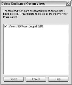
You cannot keep any views that were set to show secondary options that no longer exist. Therefore, Revit will display a dialog box asking you to delete any views that were set up to display options that you're deleting (Figure 10.10). Click Delete to continue, and the views will be removed from your project.
In the following exercise, you'll make three different office layouts, shown in Figure 10.11, using design options. Option 1 is a hybrid design of open space and closed offices, Option 2 is an open office with cubicles, and Option 3 has only enclosed offices.
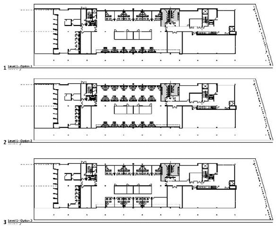
Once created, all the options will exist in one file and can be separately displayed in different views or dropped on one sheet for comparison. Follow these steps:
Open the Foundation_chapter_10 model in the Chapter 10 folder of the book's companion web page (
www.sybex.com/go/masteringrevit2010).Open the Level 1 Presentation plan view.
From the Manage tab, select the Design Options button.
Create a new Design option set called Interior Fitout.
Create three options, and set Option 1 to be primary by clicking the Make Primary button, as shown in Figure 10.12 (this should be set by default).
Close the dialog box.
Choose to edit Option 1, using the drop-down list from the Design Options panel.
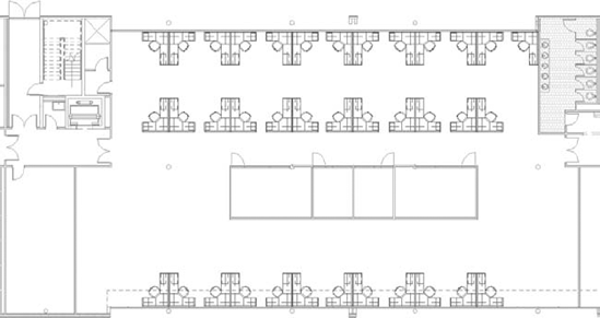
While editing Option 1, place a series of workstation families (
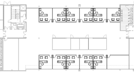
workstation.rfa) located in the Project Browser, under Families | Furniture Systems. Also add interior partitions and offices to create a layout similar to the one shown in Figure 10.13.Finish editing the options either by selecting the Design Options button and clicking the Finish Editing button or by simply switching to the Main model in the drop-down list of the available options in the Design panel.
Choose Option 2 from the drop-down list to start editing that option.
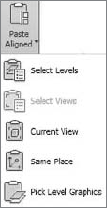
For Option 2, create an open floor plan layout similar to the one shown in Figure 10.14. You can simply draw this option layout. Alternatively, to speed up the process, you can choose to edit Option 1, copy the row of cubicle desks to the clipboard using Ctrl+C, choose to edit the Option 2 from the drop-down list, and paste the desks in using the Paste Aligned

When you've finished, select Main Model from the drop-down list in the Design Options panel to return to the main model. This finishes editing any particular option.
The elements in Option 2 will disappear from the view. The primary option (Option 1) is set to be visible by default, and as mentioned earlier, you can't view more than one option per view.
To make a third option that has enclosed offices and no cubicles, again you can either draw everything in that option from zero or you can choose to edit Option 1, select all the offices in the top half of the space, and copy them to the clipboard using Ctrl+C or the Copy command from the Clipboard panel.
Choose Option 3 from the drop-down list of available options in the Design Options panel.
From the Clipboard panel of the Modify tab, choose Paste Aligned
The workstations are copied into Option 3.
Continue to fill the space with offices, drawing the partition walls as shown in Figure 10.16. You can use the Mirror command to speed up the process.

Next, you need to place each option on a sheet so you can show the options to your client and get feedback about the various layout options. To do that you will first need to create duplicated views, assign different design options to them, and finally place them on a sheet. Follow these steps:
Duplicate the Level 1 plan view from the Project Browser and rename the copy Level 1 - Option 1.
Duplicate the Level 1 plan view two more times, and give each view a unique name: Level 1 - Option 2 and Level 1 - Option 3.
Open the Level 1 - Option 3 view, open the Visibility/Graphic Overrides dialog box, and select the Design Options tab. Change the Design Option value from Automatic to Option 3.
Open Level 1 - Option 2, and repeat step 3, but make sure Design Option is set to Option 2. For Option 1 you can repeat the process, but you don't need to do anything for the Level 1 - Option 1 view as it will be, as it's a primary option automatically assigned to be visible with the Main model. You have thus created three views of the same floor plan, each showing a different design option.
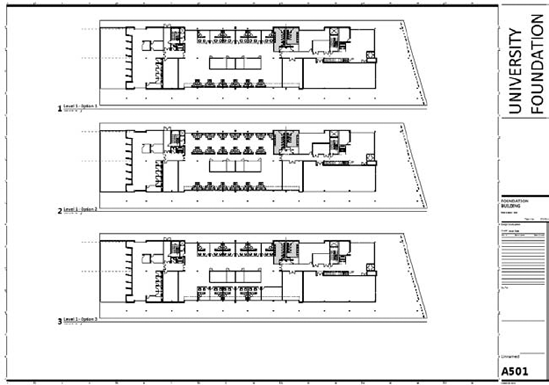
Create a new sheet view, and drag each of the plans onto the sheet, as shown in Figure 10.17.
You're now ready to present your alternatives. By associating schedules to design options, you can further illustrate the implications of various design decisions for your client.
Now that we have discussed the ability to have different design options within Revit and how to show these various solutions, let's dig into a little more detail and talk about other ways to consider the various solutions. As any designer knows, multiple factors come into play with any design solution—beauty, functionality, cost, and sustainability, to name a few.
When presenting design options to a client, schedules allow you to compare the cost of adding particular features to different design options. A schedule, like any view, can be tailored to show specific design options. Here's how to create a schedule of elements in a design option.
Switch to the View tab.

From the Create panel, click the Schedules button and select the Schedule/Quantities tool. Choose the category you'd like to schedule and the appropriate parameters.
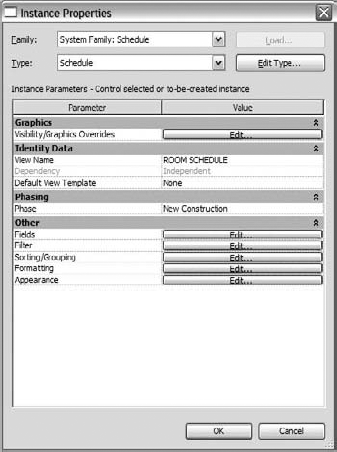
Right click on the newly created schedule in the project browser and select Properties. From the Instance Properties dialog box (Figure 10.18), you can access the Visibility/Graphic Overrides dialog box and change the design option. The properties of the schedule include a parameter for Visibility/Graphics Overrides.
Click the Edit button. This brings you to the Design Options tab (in this case, the only tab in the dialog box), where you can choose a design option to schedule. Here is this feature's real power: only elements belonging to the selected category in the selected design option are included in the schedule.
You can create rooms in design options to compare areas and create color schemes for various options. Revit allows you to create multiple independent room layouts in the same model. For example, you can create two office layouts with different sizes and number of offices in each option and then add rooms to the offices. You can then create views of each option that are color-coded to provide a nice visual comparison. To get a feel for how this works, consider this simple example.
Start with a corridor and rooms on either side. You need to create two design options that show different room configurations. Follow these steps:
Draw a simple layout of walls, as shown here in plan view.

Open the Design Options dialog box from the the Design Options button on the Manage Tab, and create an option set named Office Configurations. Add two design options to the set, as shown in Figure 10.19.
Back in the plan view, duplicate the view from the Project Browser. Name the view Level 1 Plan View - Option 2. In the Visibility/Graphic Overrides dialog box for that new view, select the Options tab and set Option to Option 2.
Go back to your original Level 1 view and change the Options Visibility/Graphic Overrides setting to Option 1.
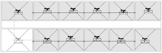
In the Option 1 plan view, choose to edit the option. Draw walls to create 12 offices, as shown here.
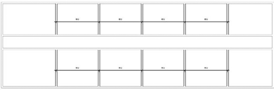
Add rooms to each office using the Room tool from the Room and Area panel of the Home tab. Your design should resemble this graphic.
These rooms are added to the primary option.
Open Plan View - Option 2, and click to edit Option 2 from the drop-down list of Design Options in the Design Options pane of the Manage tab. Place walls so that you make 10 offices rather than 12, and place rooms in each office space, as shown here.

To create a schedule of the rooms in each option, select the Visibility/Graphics Overrides parameter in the Instance Properties of the room schedule, and set the design option to the desired option (Figure 10.20).
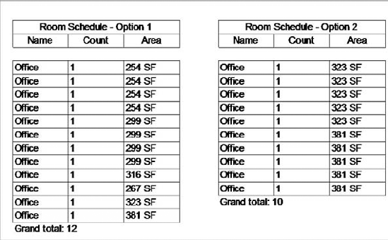
Make a schedule for each design option showing rooms, areas, and count. Be sure to name each schedule so that it corresponds to your design options. You can then place each schedule and plan view on a sheet for comparison (Figure 10.21). Don't be confused if the total areas of two options differ, even though the overall space is the same. This results from the spaces being measured to other than the center of each wall, such as the wall finish. More spaces require more partitions, resulting in different area totals. And with less usable space, you begin to understand why open-space offices are more common than partitioned offices.


- Use Revit design options.
Design options provide a means to maintain two or more alternative designs for the same project or component.
- Master It
What are design options in Revit?
- Decide on a design solution.
The end result of exploring multiple options is to choose one alternative and implement that choice.
- Master It
You've explored a number of design options for an entry scheme. Your client has selected one, and you need to incorporate it into the rest of the model and remove the unwanted alternates.
- Use design options with parametric design.
Making quantitative differences visible is an essential part of presenting multiple alternatives.
- Master It
You need to look at some seating layout options for an auditorium space based on different-sized seating and show the seating counts.
