
In this chapter we discuss how to expand the model documentation to include construction details. Details are typically created by embellishing section or plan views of the model with additional 2D elements. The use of 2D detail families in Revit allows you to complete a set of construction documents for a client or contractor quickly and easily without the burden of having to model every component and detail within the project in 3D.
In this chapter, you'll learn to:
Create drafting views
Import and link CAD details
Create 2D detail components
In the lifecycle of a project, eventually it becomes necessary to add details to the model that are then used to build the building. Historically, the conceptual design, schematic design, and design development project phases progressed through a series of refinements to develop the final set of construction documents. With a BIM process, these discrete phases are redefined, but the workflow remains essentially the same. At the stage prior to adding details, the "big idea" is refined and most plans and building sections are in place. Materiality is added to the design, and the assemblies that make up walls, floors, and ceilings are added. Creating wall sections, schedules, and enlarged plans helps to describe the project further. Eventually, the systems solidify and details are created that truly begin to define how many of these elements are put together in the field. In this chapter, we will explore a few scenarios for detailing the model and creating some of the smaller-scale drawings that go into construction documents. We will look at some of the more common methods:
Creating details from scratch
Importing details that have already been drawn
Creating the detail from the model and embellishing it using 2D detailing tools
It isn't feasible to model every single construction detail in 3D within Revit. A 2D detail often provides enough information for construction in the field. To this end, Revit provides a means of drafting in views strictly used for 2D information that can be placed on sheets like any other view. These views are called drafting views and document typical or special details of the project. They can be created by drawing the details directly within the view or by importing details. They can also have legends, maps, text, or any of a variety of graphics necessary for a construction document set. When placed on a sheet, drafting views have the same intelligent referencing as all the other views within Revit. Even though drafting views present only 2D information, they are still tied parametrically to sheets, so all the references are dynamic and coordinated.
To create a new drafting view, follow these steps:

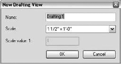
In the dialog box that appears, enter a name in the Name field (Figure 21.1) to name the view. This is the default name that will appear when the drafting view is placed on a sheet in the drawing set.
Using the Scale drop-down list, choose a scale.
Click OK. A new node, Drafting Views, is added to the Project Browser. This new drafting view is primed for either drafting a new detail or importing existing CAD details. This essentially creates a blank sheet within Revit for you to begin drafting (or importing) 2D details.
It is common to have details from manufacturers you'd like to include in your drawing set, or you may have standard details from an office detail library that need to be included in your documents. What if all these files were created in a 2D CAD application? As we discussed earlier, you can easily import these 2D details into Revit to be used and reused across many BIM projects.
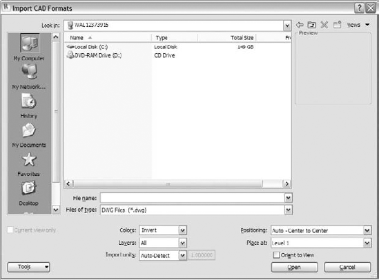
To see the types of CAD files you can import into Revit, open the Insert tab, and choose Import CAD to open the dialog box shown in Figure 21.2. The Files of Type pull-down menu contains all the file types you can import into Revit: .dwg, .dfx, .dgn, .sat, and .skp. You can also import images into Revit by using the Image command, located next to the Import CAD button on the same tab.
Later in this chapter, we'll see how each of these file types is used, but first we want to make sure you understand the distinction between importing and linking.
Use linking when you have files that will update throughout the design process. Imagine a person in your office who does nothing but develop 2D details and who works in parallel with you. With linking, the details will update constantly, as revisions are made, and you won't need to manually re-import the work. By linking the file into Revit, you ensure that the information will update as the source file changes. Linking creates a live connection to a file. This allows you to work on the linked file and then have the Revit model update to reflect the changes in the link. This behavior is similar to an XREF in AutoCAD.
Use importing when you want to embed the CAD file within the project file itself. This might be of value if you need to modify imported details slightly, because unlike linked files, imported files can be exploded and thereby modified.
The ability to link one file into another can be helpful in a collaborative environment. Perhaps someone on your team—a person working on details within your office or an external consultant—is working in a CAD environment while you build the project in Revit. Linking lets you have their latest work updated in your Revit model. If you import without linking, you get a static file that will not update if changes are made to the original file. When you link, however, it's possible to always get the latest state of the DWG by updating the link within Revit.
From the Insert tab, choose Manage Links to access the dialog box shown in Figure 21.3. Using this dialog box you can reload, unload, import, or remove a CAD link, or see what is already loaded.

Site plans, consultant files, and details or drawings done with CAD technologies on prior projects are all examples of information you may want to link or import into Revit. This isn't limited to 2D data; you can link 3D files as well. The data you import or link into your model can be view specific, meaning that it is imported in one view only—using the Current View Only import option—as opposed to all views. Start by opening the view into which you want to bring data. Go to the Insert tab, and then choose either the Import CAD or the Link CAD button, depending on your workflow. As shown in Table 21.1, you can link/import five types of CAD files in 2D or 3D in Revit.
Table 21.1. Importable/Linkable CAD File Types
Types of Files | |
|---|---|
| Files made from AutoCAD or other applications that can export to this industry standard format. |
| Drawing Exchange Format files. Most software packages can write to DXF in addition to their native format. |
| MicroStation native files. |
| Standard ACIS text files; many modeling and fabricationapplications can write to this file type. |
| SketchUp native files. |
- Linking
If you link a file, any changes made in that original file will be apparent in the Revit file in which it was linked. If your office or team workflow has personnel who are dedicated to working solely on details in a 2D environment, they can continue creating and changing the details in CAD and you can update the link to reflect the changes automatically. You can also manipulate the linked file through the Manage Links dialog box (Insert

Note that you cannot modify a linked import, because modifying any information requires explosion of the import, which the linking method does not allow. However, you do have the ability to manage the layers in the linked file and turn them on or off as needed, without the ability to explode the file. This can all be done through the Visibility/Graphic Overrides dialog box.
- Importing
An import is not tied to an external file, which means you can modify the CAD drawing directly in Revit by first exploding it. Once an import has been exploded, the import ceases to exist and everything becomes part of the Revit file. The import is translated into a bunch of lines and they are just that: lines, with no inherent intelligence. In addition, any line names or styles from the CAD layers that have been imported will become Revit line styles.
There are a series of options that you will need to understand and set during the Import/Link function, depending on the result you would like to achieve with the file that will be imported or linked:
- Current View Only
Selecting the Current View Only check box (located at the far left of the dialog box) brings the linked or imported file into only the view that is currently active. It's not always desirable to see your CAD files in all the views in your model. A site plan, as an example, doesn't have to be seen in all floors of a building—just the site view and maybe the Level 1 (ground floor) view. More often than not, you'll want to select this check box, because you will likely want to limit the number of views in which your linked files appear. If you import with this option unchecked, the file will be visible in all of your views (and any new views you create), plus you'll need to manage the visibility via the Visibility/Graphic Overrides dialog box or view templates. If you import your CAD file into one view and would like to have it in others, you can easily copy and paste it from one view to the next.
- Layers
The Layers drop-down menu gives you the option to import or link in all the layers, only the layers that were visible at the time the CAD file was last saved, or a selected group of layers from a secondary dialog box. (Layers are a DWG-based naming convention. Revit allows the same functionality with levels from DGN drawings.)
- Layer/Level Colors
The default view background in AutoCAD is usually black, so the colors used in AutoCAD are easily visible on a black background. When you import a DWG file into Revit, which has a white background, many of the colors usually used in AutoCAD (yellow, light green, magenta, cyan) are often difficult to read. Revit recognizes this issue, and in the Layer/Level Colors section of the Import/Link dialog box you have the option to invert these colors. You also have the option to not change the colors or to convert them to black.
- Import Units
The Import Units section of the Import/Link dialog box allows you to let Revit autodetect the scale at which the imported or linked drawing was created and convert accordingly. Or you can do the detection manually and apply a scale factor using the Custom Factor option.
It is not possible, or always desirable, to communicate the entire project in 3D. At times your workflow will demand using 2D graphics from a past project, manufacturer's library, or other resource. To optimize the performance of imported CAD files in your model, we strongly recommend that you delete all the superfluous data in the CAD file before importing it into Revit. Here are some general tips to help your workflow:
If your import contains hatches or annotations that you don't intend to use in Revit, delete them before importing.
Import only one detail at a time so you can take better advantage of Revit's ability to manage sheet referencing. If you have a series of details organized in a single CAD file that you'd like to import into Revit, isolate each detail, save it as a separate file, and then import.
Consider annotating in Revit and removing the annotations from CAD. This can help keep consistency in your documents. If you use arrowheads or leaders in your CAD file, they will import into Revit (when exploded) as polylines. Consider drawing the arrows within Revit.
Make sure you import the CAD details using the proper line weights, colors, and styles. Check your CAD file before importing into Revit to make sure it is consistent with your office's standards.
Every time you explode a CAD file in Revit, you add objects to the database. An inserted CAD file is one object. An exploded CAD file in Revit consists of many objects—maybe thousands of objects. For best performance, we recommend you explode CAD files as seldom as possible. If you must explode the CAD file, be sure to remove any unwanted or unneeded linework from the file in CAD before inserting it and exploding it in Revit.
Revit doesn't allow line segments shorter than 1/32″. Take care when exploding CAD details with very small line segments. Revit will remove them upon exploding.
The ability to communicate and share design intent with others is critical to any design and documentation process. With that inevitably comes the need to translate or transfer ideas, drawings, and information from one format to another to create a versatile workflow. Revit recognizes this need to share information and allows you to import and export CAD-based drawings to aid in communication.
If you're working with someone who produces details using only CAD, you can incorporate their work into your Revit model without disrupting the workflow.
It is common to have a library of existing details that can be used for many projects. This example demonstrates the process of getting these details into a Revit project using a DWG file you can download from the book's companion web page (www.sybex.com/go/masteringrevit2010):
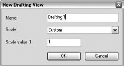
Create a new drafting view. Under the View tab, choose Drafting View and give it a custom scale of 1:1.
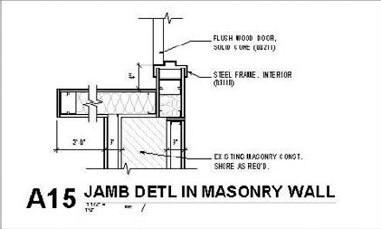
Link your CAD detail. In this example, we have a typical doorjamb detail that is already noted and dimensioned. Choose Link CAD from the Insert tab, and set these options:
Colors: Black and White
Positioning: Auto Center to Center (the default)
Choose detail
B2020A-01.dwg(located on this book's companion web page), and click OK. This will import your CAD file into a new drafting view.Now you can change your view scale to match the scale in which you'd like your detail to be displayed. For your detail, change the scale to read 1½″ = 1′−0″.
In this detail, note that the wall tags are unnecessary. Unfortunately, they were not deleted in the original CAD file (the recommended practice) before we linked the file.
So, you have two options. One is to address the issue in CAD—delete the tags there and relink the file. For this exercise we'll assume that's not feasible. Your second option is to manage the layers of the link within Revit and simply turn off the layer on which the tag has been placed. As mentioned earlier, you can do this using the Visibility/Graphic Overrides dialog box. You can also do it through Revit's graphical interface. Selecting the detail will expose useful tools in the Ribbon, such as the Query tool:

Clicking the Query button allows you to select elements in an imported or linked CAD file and discover what layer they belong to. With Query enabled, you can select any of the lines or hatches of the CAD file. Choose the border of the wall tag. This gives you the dialog box shown here, which tells you the Entity, its Layer, Block Name, and Style:

The Import Instance Query dialog box also allows you to delete the entity (which we do not want to do here) or hide the layer. Choosing Hide in View turns that layer off in this view. It can be turned on again with the Visibility/Graphic Overrides dialog box.
Now the detail is complete, you can drag and drop the drafting view from the Project Browser onto the sheetA350 Details. If you need more details from CAD files for our project, simply create more drafting views.
The finished detail is shown here. The imported detail on the printed sheet should be indistinguishable from the details created in Revit.
Creating two-dimensional detail components is a powerful way to utilize parametric capabilities built into Revit to produce the necessary details that will help tell the contractor how to create the building. Learning how to leverage these detail types can make the detailing process much more efficient.
Detail groups are similar to blocks in AutoCAD. They're collections of 2D graphics (drafting lines, other detail groups, 2D content) and represent details that you'll probably want to use again and again in the same or different views. A classic example is wood studs or blocking. You can easily set up a Revit group and use that group over and over in the model. Doing so helps control consistency throughout the drawing.
To place a detail group, use the Detail Group button in the Detail panel on the Annotate tab. Then use the Type Selector to choose which group you want to place.
Detail components are 2D families that can be made parametric. They're similar to detail groups, but are created in the Family Editor and can thus be designed with dimensional variation built into the family. In other words, a full range of shapes can be available in a single detail component. Because they are families, they can also be stored in your office library and shared across projects easily.

To add a detail component to your drawing, select Detail Component from the Component drop-down list located on the Annotate tab. Use the Type Selector to choose which detail to place. If you already have preloaded detail components in your project, you can search in your Project Browser, under Families
If you need to load a new component, click the Load Family button that shows up in the Ribbon when placing a component. Browse to the Detail Components folder. Revit has a wide range of common detail components in the default library.
To make a new detail component, use the Family Editor and Detail Component.rft template, accessed from the Application menu, under New Family. Once in the Family Editor, you can begin drawing lines, adding parametric values, and then save the file as an independent family that can be loaded into any project.
A masking region is designed to hide portions of the model that you don't want to see in a certain view. This tool is known to many users of AutoCAD as the "wipeout" tool and serves to make white masks over graphics or text. The masking region places a 2D shape on top of the model that masks elements behind it.

To add a masking region to your view, click the Masking Region button in the Region drop-down on the Annotate tab.
This takes you to a mode where you draw a closed loop of boundary lines over the area you wish to mask. When you draw a masking region, you can assign the boundary lines different line styles—check the Type Selector to make sure you're using the line style you want. One of the line styles that is particularly useful for the Masking Region tool is the Invisible Line style. It allows you to create a borderless region, which is ideal if you want to mask an element in the model. A masking region is shown in Figure 21.4. Note that masking regions do not mask text, annotations, or leaders.

Repeating details are a common occurrence in architectural projects. Masonry walls, metal decking, and roof tiles all are potentially repeating shapes that can create a repeating detail. Most of these elements aren't modeled as 3D components in Revit but are repetitions of symbolic detail components.

You create repeating details in Revit by clicking Annotate
Figure 21.5 shows the Type Properties dialog box for a repeating brick detail. When you select a repeating detail, the Type Selector is activated so that you can select any repeating detail you've already loaded in the project. Repeating details are similar to families: they have types and properties. If you don't have the repeating detail that you want loaded, it's easy enough to create one on the fly. All you need is a detail component that you wish to repeat.

Placing a repeating detail is similar to drawing a line: it requires just one click to indicate a start point and a second click to indicate an end point. After you do this, repeating 2D geometry will fill in between the clicks. Take these steps to create a repeating detail:
Select Annotate
Click the Element Properties button.
Click Edit Type.
Click Duplicate.
Give your new repeating detail a name.
Select a detail component to repeat.
The default repeating detail in Revit is a running brick pattern. If you look at it in detail, it consists of a brick detail component and a mortar joint (Figure 21.6).

When you create a repeating detail layout, measure the distance between the beginning of the brick and the end of the mortar joint to understand the module on which the detail will repeat. When the detail component is inserted, it acts like a Line tool and allows you to pull a line of brick, as shown in Figure 21.7. This line can be lengthened, shortened, or rotated like any other line. The line will automatically expand in length based on the module of the repeating detail.

If you're making a repeating detail from a component that isn't loaded in your project, you won't find it listed next to the Detail parameter in the Type Properties dialog box. This is because you first need to load that detail component in your project and then make a repeating detail component with it. The Properties window will then look like Figure 21.8. Let's take a look at the different parameters that you can set using this dialog box.

- Detail
This setting allows you to select the detail component to be repeated.
- Layout
This option offers four different modes:
- Fixed Distance
This represents the path drawn between the start and end point when the repeating detail is the length at which your component repeats at a distance of the value set for spacing.
- Fixed Number
This mode sets the number of times a component repeats itself in the space between the start and end point (the length of the path).
- Fill Available Space
Regardless of the value you choose for Spacing, the detail component is repeated on the path using its actual width as the Spacing value.
- Maximum Spacing
The detail component is repeated using the set spacing, and the number of repeated components is set so that only complete components are drawn. Revit creates as many copies of the component as will fit on the path.
- Inside
This option adjusts the start point and end point of the detail components that make up the repeating detail.
- Spacing
This option is active only when Fixed Distance or Maximum Spacing is selected as the method of repetition. It represents the distance at which you want the repeating detail component to repeat. It doesn't have to be the actual width of the detail component.
- Detail Rotation
This option allows you to rotate the detail component in the repeating detail.
You can use the Detail Component tool to create custom line types (lines with letters or numbers for various services such as fireproofing, rated walls, and fencing). Note that when you create a detail component, you can't use text for the letters; you need to draw the letters or text using lines. Figure 21.9 shows the creation of a detail component in the Family Editor and the final result used as a repeating detail in the project environment.

Other tools located on the Annotate tab worth understanding are the Insulation tool, Filled Region tool, and Show/Remove Hidden Lines tool. Each serves important purposes in your drawings.
- Width
This parameter is used to control the thickness (referred to as Width in Revit) of the insulation that is used. The Width parameter is also available in the Options bar when Insulation is selected (see Figure 21.10).
- Insulation Bulge to Width Ratio
This parameter is used to control the density of the circles used in the insulation line and can be set in the Options bar when the Insulation tool is selected. In most cases, you'll have two lines representing the space in the wall where the insulation needs to fit. Revit allows you to place the insulation using the centerline of the insulation as a location line.


A region consists of a boundary—which can be created using any line style—and a fill pattern, which fills the area defined in the boundary. Figure 21.11 shows a region with a tile hatch pattern used to show tile in an interior elevation. In lieu of a complex stacked wall condition for bathroom walls, a region with a 4″-square model pattern is used to represent tile on the restroom wall. While this will not be reflected in any material take-offs, it is a quick way to create interior elevations.

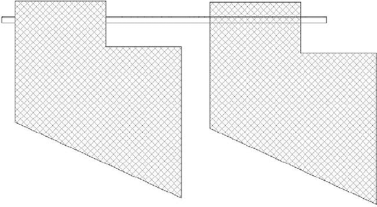
Regions can be either transparent or opaque to show or hide what is behind them. Figure 21.12 shows two regions—the left one is opaque and the right one is transparent—and how they interact differently with a model component.
Region type properties define how a fill appears, including pattern, pattern color, and transparency (Figure 21.13). Notice that the boundary lines of the region are not part of the type properties and are defined independently when the sketch is edited. To change the line thickness of the boundary, select the pattern, click Edit Boundary in the contextual tab, and change the line pattern in the Element Properties dialog box or from the Type Selector.
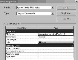
For each filled region that has a different pattern, transparency, or other variation in appearance, you need to make a new type. Remember that type properties propagate to all instances of the type, so making a change to one type may affect many instances in many different views. If you want to make a filled region that uses a new pattern, be sure to duplicate an existing type before you start changing type parameters.
Regions can use both drafting and model patterns, making them a flexible and handy tool for 2D workflows. As previously noted, drafting patterns are patterns that will maintain their separation distance relative to the printed sheet. Model patterns will maintain their separation distance relative to the model element. To describe this further, let's use two examples. If you were looking to use a cross-hatched pattern of lines, as in the example earlier for 4″ restroom wall tile, you would want to use a model pattern. The pattern would be set to 4″ and it would maintain a 4″ pattern regardless of what scale the drawing was set to. So, the pattern in a 1/8″ scale drawing will appear twice as tight as in a ¼″ scale drawing. In the example of a drafting pattern, you would want to use this in places where graphical consistency is more important than actual dimension. So, when creating a filled region that represents rigid insulation, the pattern might be set to a 1/8″ grid. It will always print as a 1/8″ grid regardless of what scale the view is set to. Just keep in mind that all of these are truly just 2D shapes with no 3D BIM characteristics.
Showing Hidden Elements with Dashed Lines
In visual communications between architects and engineers, when one element obscures another, the hidden element is usually graphically represented with dashed lines. Often, just a portion of an element is hidden. In the 2D CAD application, it can take a lot of manual work to make this possible: you will need to explode the block representing the element that has to be half-hidden, and split lines so that one portion remains solid and another converts to dashed.
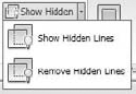
Revit has a special tool, Show Hidden Lines, for recognizing obscured elements and representing the portion that is hidden with dashed lines while still maintaining the complete object.
Select the Show Hidden Lines tool located on the Modify tab.
Click the element that obscures the object.
Click the element that is obscured. The hidden portion of the element becomes dashed. If an element is obscured with more than one element, keep repeating this operation until you get the desired look.
When you relocate or delete the obscuring element, the hidden element responds intelligently to those changes. Figure 21.14 shows an I-beam hidden by another beam. Figure 21.15 shows the results after using the Show Hidden Lines tool when the second beam is selected as an obscuring element and the I-beam is selected as an obscured element.
The Show Hidden Lines tool applies to 2D and 3D elements in all possible combinations: detail over detail, detail over model, model over detail, model over model. Right below the Show Hidden Lines tool is the Remove Hidden Lines tool, which resets the graphical display of the elements so they look as they did before you applied the hidden line behavior.

Figure 21.14. An I-beam hidden by another element.

Figure 21.15. The I-beam after using the Show Hidden Lines tool.
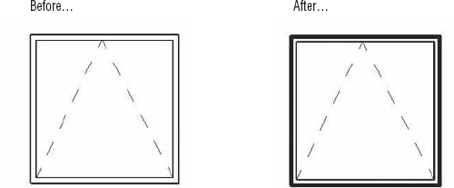
To use this tool, click the Linework button located on the Modify tab, choose a line style from the Type Selector, and begin picking lines in any view. Once a line style is selected, you can continue selecting lines to override. To change the length of the new linework that has been applied over the existing model element, use the blue grip controls. Figure 21.16 shows an unaltered elevation of a window and the finished view.
Callouts are another view type in Revit. They are used extensively in plans and sections to indicate a more detailed view of various conditions in any type of construction document package. Figure 21.17 shows two callouts in a wall section.

In Revit, there are two types of callouts you can choose when creating new details: one for floor plans and one for details.

Depending on the type of callout you select, it will appear under different folders in the Project Browser. Choosing a floor plan callout will add a new view under Floor Plans in the Project Browser called Callout of <view name>.
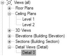
Choosing Detail Callout will add a new view under the Detail Views (Detail) heading. The subsequent view will be by default named Detail 0, Detail 1, Detail 2, and so on (Figure 21.18). For the ease of finding and organizing your views, be sure to choose the correct view type when creating a new view.
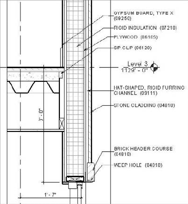
Now that we have discussed many of the tools used for detailing in Revit, let's step through a detail and see how these tools can be put to practical use. For this exercise, a detailed wall section will be used to illustrate a workflow. In the Foundation_Start.rvt.ext file found in the Chapter 21 section of this book's companion web page, Detail A14 on Sheet A301 (Figure 21.19) is a wall section at the east entry. Since we already discussed dimensioning and keynoting in Chapter 19, "Annotating Your Model," those items have already been added to the view.

In this view, the only things that have been added are text notes and dimensions. The rest of the model graphics were automatically generated the moment the section was placed in plan view. To add more detail, start by adding callout detail bubbles at each major construction join. Use the Callout tool on the View tab (Figure 21.20).

In this wall section, we need four 1″ = 1′−0″ callouts:
The roof/wall condition (Roof Detl, Typ)
The wall/floor condition capturing window heads and sills (Floor Detl, Typ)
The exterior storefront (Head @ Storefront, typ)
The interior storefront (Storefront Head Detl)
Using the Callout tool, create callouts in those locations. You can make the first three callouts by choosing the Callout tool and drawing a rectangle around the detail condition. For the interior storefront, a different method will be used that takes advantage of an existing CAD drawing by referencing it rather than making a new view of the model.
To do this, follow these steps:
Create a new drafting view. Under the View tab, choose Drafting View and give it a custom scale of 1:1.
Import your CAD detail in the drafting view. In this example, a typical doorjamb detail is already noted and dimensioned. On the Insert tab, choose Import CAD. Choose the detail
B2020A-02.dwgfound in the project directory on the companion website and select the following options in the dialog box:Colors: Black and White
Positioning: Auto Place Center to Center (the default)
Click OK to link the file into the view.
Change the view scale to match the scale in which you'd like your detail to be displayed. For this detail, set the scale to 1″ = 1′−0″.
Right-click the view in the Project Browser (in the Drafting Views node) and rename it Storefront Head Detl.
With the drafting view for our detail created, you can now reference that detail when making new callouts. Choose the Callout tool from the View tab, but do not draw a rectangle in the view yet. First go to the Options bar and check the Reference Other View box. This activates a drop-down menu from which you can choose the detail named Storefront Head Detl (Figure 21.21).
Once the reference view is selected, draw the callout at the interior storefront head condition.
Keep the views related by dropping them onto sheet A350.

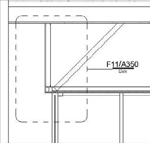
With the four details identified, you can start to add embellishment to the wall section. Beginning with the most recent detail you cut—the Storefront Head Detail condition—you need to do a little work in the section to match the CAD detail you'll use for this condition. Because this is a unique condition you will see in only this one detail, you'll not need to model the assembly but rather create it using the annotation tools. In Figure 21.22, you can see the current condition of the modeled wall section (A) and what we have imported as a similar condition (B) for our CAD detail.
You need to show the soffit and head condition at a lower level of detail within the wall section to make the detail work. As you can see in the detail and wall section shown in Figure 21.22, the ceiling's condition above the window head does not coincide. The wall section needs to be edited to match the detail by extending the ceiling so that it overhangs 5″ (13cm).
In the section view, select the ceiling and choose Edit Boundary from the contextual ribbon. Revit will alert you to the fact that the ceiling cannot be edited in the section view and will let you switch views (Figure 21.23). Choose Reflected Ceiling Plan: Level 1.
The Reflected Ceiling Plan (RCP) view will open, and you'll be placed in boundary edit mode to modify the ceiling over the entry. According to the detail, we need a 5″ (13cm) projection past the head of the door for the design (Figure 21.24).
Finish the ceiling and return to the section view to see the effect (Figure 21.25).


Looking at the detail, we see the need to add some blocking and 3½″ (8cm) studs. This type of element is likely to be used throughout the model, so it makes sense to use a detail component rather than draw them as individual 2D lines. There will be some strictly 2D drafting lines to add later to this wall section for sealant and flashing, but first you'll need to add architectural elements like blocking.
To represent the blocking you need above the window head, you'll use a premade detail component from the Revit library and load it in the project.
On the Annotate tab, open the Component drop-down list; choose Detail Component and then Load Family. Browse to Detail Components
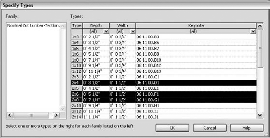
A list of predefined types will show up at the bottom of the dialog box. Since you are not sure which type you want right now, select a few of them by holding down the Ctrl key and selecting 2 × 4, 2 × 6, and 2 × 8 from the menu (Figure 21.26).
This loads the family and the types into the project. Click the Detail Component button and choose 2 × 4 from the Type Selector. Insert it in the general location shown in Figure 21.27. We can then rotate it and move it into place.
For printing purposes, the line weight for the default 2 × 4 detail component is too thick and needs to be adjusted. Because elements are so simple to modify, you will find yourself changing stock components to better meet the needs of your office.
For the 2 × 4 you just inserted, the line weight of the border can be changed by selecting the component and clicking the Edit Family button in the contextual tab. You'll get a confirmation dialog box before going directly to the Family Editor to change the component. Click Yes.

To change the thickness of the border, first hover the cursor over the element to see what it is. You'll see that this component is made of a masking region and some detail lines. Select the masking region (Figure 21.28) and click Edit Boundary in the contextual tab.
This opens the boundary edit mode of the masking region. Select the boundary lines and use the Type Selector to change them from heavy lines to medium lines. These line styles are actually subcategories of the Detail Items category, which you can access from the Object Styles dialog box shown in Figure 21.29 (select the Manage tab and choose Settings
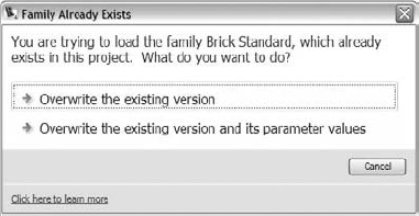
Clicking Finish Region completes the masking region. Clicking the Load into Project button loads the changes back into the model. You will be prompted to override parameter values of existing types. Click Overwrite the Existing Version.
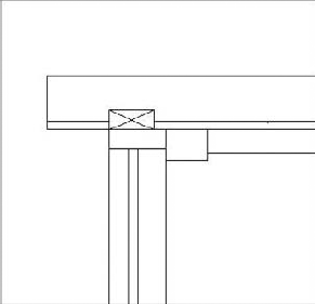
The blocking displays much better, as you can see in Figure 21.30.
Moving the component into place, use the fact that it was created as a masking region to cover some unwanted gypsum board above the door head.
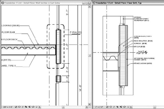
Don't forget that you have the ability to see multiple views at once. By closing all views but this detail and the wall section, you can choose Tile on the View tab's Windows panel and see both views side by side (Figure 21.31).
The same procedure can be followed to place metal studs in this detail by loading them from Detail Components


There is one more element to add before we begin drafting lines to finish the detail. There is a ¾″ piece of plywood backing over the entryway in our detail that does not appear in our wall section. You can represent that with a filled region.
Select the Region tool from the Annotate tab.
Set the boundary lines to thin lines using the Type Selector and draw a box ¾″ tall on top of the gypsum board that will represent the plywood.
Choose Region Properties in the contextual tab; select Edit Type and then Duplicate. Name it Plywood.
Change the Background parameter to Opaque.
Set the Fill Pattern to the Wood_Glu-LamBeam pattern (Figure 21.32).
Click OK to complete the new type; then click the Finish Boundary to complete the filled region.

To complete the detail, use detail lines on the Annotate tab. These lines are similar in nature to most drafting applications. Choose the Detail Lines tool, select the desired line type from the Type Selector, and start drafting. By using some thin, medium, and hidden lines, you'll be able to quickly complete this detail (Figure 21.33).
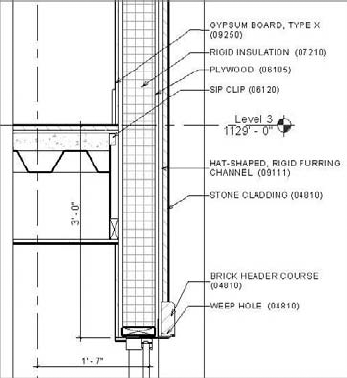
Now that you have explored the use of some of the drafting tools for a typical detail, let's look at some of the more common detail types when there is no SIM (Similar) condition and only the model data. You will begin this exercise by working on the detail in the same wall section at the floor of Level 3. This will allow you to work on the head and sill conditions of the windows at the same time. The detail right out of the model looks like Figure 21.34 (again, using the tiled views to see both conditions at same time).

Since Revit is parametric, you can actually work in either the detail or wall section as changes to the model changes will propagate everywhere. For this exercise, you will be working directly in the detail with the understanding that the wall section will also be updated. The finished detail you are going to create is shown on Figure 21.35.
Design is cyclical in nature. Just because you think that in one phase you won't need more than one detail of a condition doesn't mean it will remain like that throughout the rest of the project. We have found it useful to use Copy and Paste and filtered selections together.

The first thing you need to modify for this detail is the floor condition. Since the project is using a structurally insulated panel (SIP) for the skin, we cannot have the floor slab bearing on the insulation inside the panel. In reality, the panel will be clipped and hung from the side of the floor system. You'll need to pull the edge of the floor back to 1 ½″ from the inside face of the wall. You can do this the same way you fixed the ceiling in the detail earlier.
Select the floor and choose Edit Floor from the contextual ribbon.
When prompted for a view to edit the floor in, choose Floor Plan: Level 3.
Move the slab edge on that wall 1½″ from the inside face of the wall and click Finish Sketch.
The revised detail should look like Figure 21.36.

Obviously, you can't run gypsum board back behind the slab and we still don't have a clip to hold up our structurally insulated panel (SIP) panel. However, based on all the wall sections and details we have, it doesn't make sense to create this out of detail lines, and there is no default Revit detail component for this condition. Instead, you will make your own detail component to reuse for this condition. Detail components are like any other family in Revit. Once added to the drawing, you can always reedit and update them with new information. In the next exercise, you will make a quick and simple detail component—a masking region to hide the gypsum board on the SIP wall system.
From the Application menu, choose New
In the Family Editor, select the Masking Region tool from the Family tab in the Design bar.
You need to create a masking region 7/8″ wide × 1′−8″ long to hide that run of gypsum board. You also want to make three sides (top, bottom, and right) medium lines because they will represent cut material and the left line an <Invisible Lines> type to keep it hidden. Invisible lines will show as gray when drawn in Sketch mode but will not appear at all and hide other lines (if on top) in model views. Since the masking region is overextended, you need to cut the top and bottom lines. Notice in Figure 21.37 that the left line of the rectangle appears as gray because it is an invisible line.
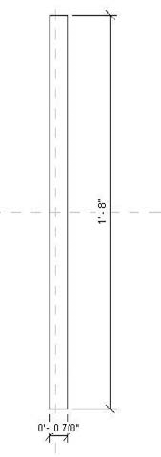
Masking regions are very precisely shaped elements. The reason this masking region is 7/8″ wide is to cover the 5/8″ gypsum board, taking into account that the line weight of the gypsum adds thickness to the line; this needs to be covered by the masking region.
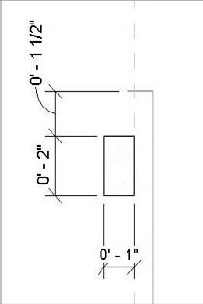
Now you need to draw the clip. For the moment, the clip can be represented by a simple filled region box 2″ high and 1″ wide, located 1½″ down from the top of the finished floor on the right side of the masking region.
Using medium lines, create the box as shown in Figure 21.38.
Before finishing the boundary, choose Region Properties and select the Aluminum pattern. Click OK and then choose Finish Sketch. The finished component should look like Figure 21.39.
If you choose Load into Project right now, it will load with a default name of Family1, which is not highly descriptive and not easy to relocate when you want to use it again. Take a moment and save the detail component to your project directory or library as
SIP Clip.rfa. Now load it into your project, as shown in Figure 21.40.Because you have chosen a detail component, you have the added benefit of being able to keynote it, which you will need for the detail. Because this is a 2D, view-specific element, use the User keynote.


To finish cleaning up this floor condition, a few more items can be added by placing base molding around the floor/wall condition and then bringing the ceiling finish of the second floor to meet the wall and the floor finish to meet the wall.
For this detail, it is easiest to make a simple detail component. This will make it reusable and taggable—something you wouldn't get with mere lines.
Choose Application
Draw a simple 6″ × ½″ rectangle using a masking region and thin lines.
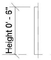
This time, add a parameter to the base in case you want to change the height later in the design. Add a dimension to the base from top to bottom (Figure 21.41). Selecting the dimension, choose the Label drop-down from the Options bar and choose <Add Parameter...>.
In the Parameter Properties dialog box, name it Height and choose Dimensions from the categories (Figure 21.42).

If you choose to change the height of the base later in the project, you don't have to reedit the family. It is simply a matter of changing the parameter using the following steps:
Save the file to your project director or library as
6in base.rfaand load it into the project.Place it in the model (Figure 21.43).

In Revit there are a number of ways to create a detail. There is no single best solution, just as there is not one way to build something on site. We chose to cut the floor back from the wall and use filled regions to re-extend the floor to meet the wall condition. We could have left the floor connected to the wall and simply used masking regions and filled regions to give the appearance of the floor structure being pushed back instead of the floor finish being pulled forward. We chose our particular method because our contractor had requested the use of the Revit model to do some concrete take-offs, so we needed to make sure the volume of concrete was as accurate as possible. Overextending or underextending that condition, even by a few inches, would have changed the volume of concrete reported in the schedule. Before choosing a direction for a workflow, it's a good idea to understand all the uses for your model (beyond documentation) and keep those in mind when making these kinds of decisions. In the following steps, these techniques will be demonstrated.
The floor line has been cut back to make room for the clips; you still need to finish detailing the subfloor and finish floor to meet the wall. To do this, you're going to create some simple filled regions.
Using the Region tool on the Annotate tab, draw a rectangle boundary at the ceiling of the second floor to close the gap for the gypsum board under our blocking (Figure 21.44).
When drawing the region rectangle, be sure to define the left line as invisible using the Type Selector so it appears continuous with the gypsum ceiling. Make the top a thin line, the right medium, and the bottom wide. Be sure to overextend the invisible line a bit to compensate for the line thicknesses.
Open the Region Properties dialog box, set Type to Gyp, and click OK. Verify that the region is opaque so you don't see the model geometry through the region.
Once you click OK, the region should look like Figure 21.45. Somehow, it is not quite right. This is because the filled region and the detail components layer can rest on top of the others. You need to resolve their order by pushing the gyp-filled region to the top.


Using this same example, you can build simple regions for the floor extension under our base. The floor condition looks like Figure 21.47.
To finish this portion of the detail, you need to add material definition to the floor. The concrete has been poured on top of a corrugated metal deck, but it is not possible to add a corrugated metal material pattern as part of our floor materials, so we want to make a repeating detail in the form of our 3¾″ corrugated deck. While the structural engineer will show this in detail, you still want to show the material architecturally in our sections and details. First, you'll need to make the profile of the deck.
Create a new detail component using the steps described earlier. You need to make a corrugated metal deck 3¾″ tall to mimic the height in the model (Figure 21.48). There are a couple of ways to make the decking in the Family Editor. One option is to simply use lines. Another option is to create it as a masking region or region. It's a matter of personal preference, and one might be better for your project workflow than the other. We only need to draw a section that can be repeated. When you're finished, save the detail component as
Mtl Deck.rfato the project folder or library.
In the Detail field, choose Mtl Deck from the drop-down menu.
Change the Detail Rotation field to 90 Degrees Clockwise.
Start drawing the element as you would a line.


Since this is a 2D element, you will also want to go back to the wall section and add the corrugated deck to all of the appropriate locations. The finished deck in detail and section looks like Figure 21.49.
There are a couple more conditions to address to finish this detail. The head and sill conditions for the storefront system will probably not be affixed directly to the rigid insulation as the detail currently shows. You'll need to add some blocking and flashing to those locations. Again, since you will want to reuse this condition in other views, you can make it with a detail component. This time, however, you are going to add a more significant level of detail to the detail component before inserting it into the model. You'll do this by nesting detail components within each other. Let's start with the storefront head condition.
Start a new detail component family using the process described earlier.
Notice that in the Family Editor, there is a Detail Component button, similar to the one in the project environment. Click it and load a 2 × 6 from the same path we used earlier (Detail Components
Use the horizontal reference plane to simulate the top of the storefront. We want to place our blocking ¼″ back from this line, centered on the vertical reference plane.
Once you click Finish Sketch, because this is a shim, you'll want to show it with a single diagonal line through it. Using the Detail Line button, you can add a detail line to make this condition.

To help finish the window on the exterior, place a stone header over the window opening. This can be created with a region and a new region type for stone. The stone head is 6″ high by 2¼″ wide and placed 1 ⅜″ from the edge of our 2 × 6. (This measurement isn't arbitrary: it is taken directly from the wall condition in the model.) Figure 21.50 shows your current progress.
You need to add a steel lintel for the stone header. Revit does not provide these as default detail components, so you can create one with a filled region.
Save this condition as
SIP Storefront Head.rfaand load it into the project.
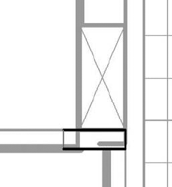
Once the detail component is inserted into the model, you should see something that looks like Figure 21.51.
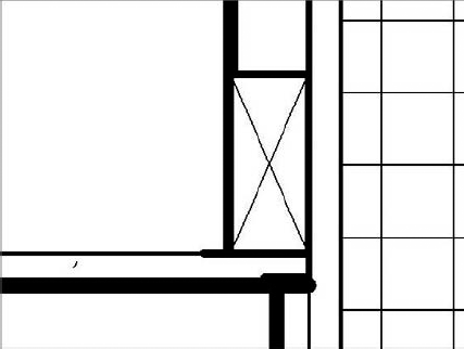
Using simple detail lines and filled regions, you can add any necessary flashing and gypsum returns to the window. The completed head condition should look like Figure 21.52.

By combining the simple tools used in the previous sections, you can easily complete this detail. As we have mentioned throughout this chapter, many of the elements that were imported or created need to be made only once. All of the families and detail components you built in the course of this detail are now available in the project for use in other views. The finished detail looks like Figure 21.53.
You can easily adapt this process to complete details for the other conditions.
- Create drafting views.
Not every drawing or view in Revit is created with model elements. Some of the views on sheets will be made solely with 2D drafting views. Knowing how to create and use these views is critical to any documentation package.
- Master It
Keeping views hyperlinked together is a key benefit to using Revit. How do you draw simple, 2D details in Revit but still keep them parametrically linked to sheets?
- Import and link CAD details.
Even if you've been using Revit for years, you will need to import 2D geometry from an old library of standards or manufacturer drawings. Understanding how to do this effectively will keep you from having performance issues with your model.
- Master It
Your office has a huge repository of standard details. How do you reuse details drawn in CAD in a Revit project?
- Create 2D detail components.
Detail components can be used again and again within a model to graphically show in 2D different typical building components. Mastering these will result in enhanced productivity when you work on a project.
- Master It
Detailing is a process of adding more granular layers of information and graphics to the model and view. What tools would you use to add 2D detail?