
CHAPTER 13
Rotator Controller
One of Dennis’s many interests in ham radio is operating “weak signal” VHF and UHF (V/UHF). And, as many V/UHF operators do, he does get involved in contesting. It is fun and when conditions are good, it can be downright exciting! Working a station across the country on 6 meters is an amazing thing when the conditions are good. HF is fun, but VHF, UHF, and microwave can be, for lack of a word, amazing! Working a station 600 miles away on 10 GHz SSB can change your life!
But, this book isn’t about weak signal operating. Still, the project discussed in this chapter can enhance the ease of operating a station with any directional antenna on a rotator, and especially those stations that have multiple directional antennas on multiple masts or towers.
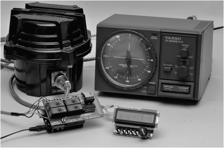
FIGURE 13-1 The Arduino Rotator Controller shown with a Yaesu G-800DXA Rotator.
Dennis’s V/UHF station is set up to operate on many bands and the antennas are located on three different towers. If you do any V/UHF contesting, you know that many of the stations you work during the contest are set up the same way, on multiple bands. Each contact you make on a different band with the same station counts as points, so you always attempt to work that station on each band while you have them, and then QSY to the next band you both have.
When you have three towers with a plethora of antennas, it can be a handful to move all of those antennas in the direction of the station you want to work. Tuning, talking, logging, switching bands, and moving multiple antennas all at once can be a handful all right. Heck, it can be a handful with just one rotator to get the antenna around in the right direction.
This project automates at least part of that process. It provides your rotator with preset antenna headings that can be used at the touch of a button. It allows you to set an arbitrary heading, press a button, and the rotator turns to that heading for you.
If this sounds good to you, read on!
The Arduino Antenna Rotator Controller
The controller is designed so that it may be used with most of the popular antenna rotators. There are some rotators, of course, that won’t work with this project, but they are few. Most rotators use a dual-winding motor to turn the antenna mast (one winding for each direction) and a potentiometer to sense the direction the antenna is pointed. Some rotators also include a solenoid-actuated brake to prevent the system from “windmilling” in a breeze. Still others use a single motor and reverse the polarity to change direction. Some rotators require a relay to handle the current of the motor switches. Another allows for driving the control head with open collector transistors, while even providing a 0–5 VDC voltage for azimuth, as well as an interface for controlling the speed of the motor.
Our controller doesn’t replace your existing control box. Instead, the controller automates the control of the rotator, supplementing the existing control box. Ideally, we would like the Arduino Rotator Controller to be totally external to the rotator control box. In the case of the Yaesu rotators, this is possible as there are external control interfaces provided by the manufacturer. However, some rotators require that connections be made internally to the rotator control box.
But, we give fair warning at this point. Antenna rotator control boxes contain lethal voltages. Extreme care is required when implementing this project. Your control box has 115 VAC line voltage, as well as lower, high-current voltages present. Never open the control box unless you know exactly what you are doing and what you will encounter. We repeat, 115 VAC can be lethal. Never work on the box when it is plugged into the wall socket. Some connections to the Arduino Rotator Controller are made on the rear apron connector of the control box. If you understand and follow the instructions we provide, you will be successful.
In general, the type of rotator control box that this works with is any type that has two lever switches, one for clockwise and one for counterclockwise rotation; a lever switch that operates a brake (most rotators these days have a brake but older ones may not); and a panel meter that indicates beam heading. This encompasses a wide variety of rotators and controllers.
Supported Rotators
This project supports a number of different rotators from different manufacturers. Table 13-1 gives a list of the rotators the project supports. In general, most rotators provide the interfaces that are easily controlled or measured externally. Most rotators use a potentiometer as a voltage divider to determine the heading of the antenna. It is a simple matter to read the voltage across the potentiometer and then calculate the heading. Many rotators use dual-winding motors, as mentioned earlier, but a few, like those made by Yaesu, use a single motor and swap the supply voltage polarity to change direction. Fortunately, most of the Yaesu rotators include a connector for external control that is very easy to interface. It provides control of direction and speed as well as providing a voltage proportional to the heading.
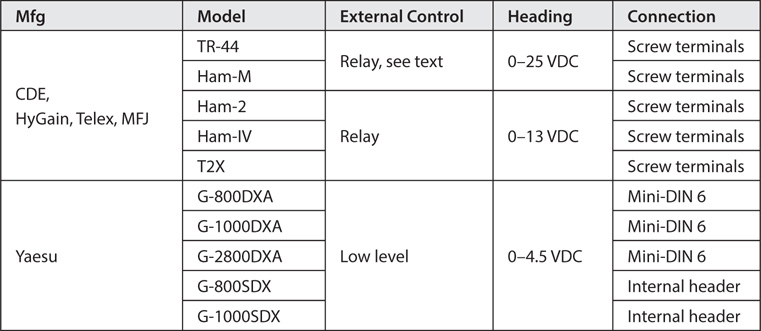
TABLE 13-1 Supported Rotators
The Arduino Rotator Controller uses two shields from previous chapters. We use the relay shield (with the addition of a header connector), and the panel meter shield. We added a new board that is the control panel for the controller. The control panel is not built on a shield but is assembled on the same style prototyping board we used for the Sequencer in Chapter 12 and is connected to the Arduino shield “stack” through a ribbon cable. The control panel contains a digital shaft encoder to set headings, switches to control functions, and an LCD for display of headings and functions.
Relay Shield
We use the Relay Shield from Chapter 11 with some consideration of parts to be used. The original relay shield was generic and used 5 V relays capable of switching up to an Amp or two. In order to switch the motor windings and brake of the rotator, the relay needs to be able to switch higher current. There is no reason why the relay shield as built in Chapter 11 couldn’t be used with external relays to switch the higher current as described in that chapter. However, we decided to use a SPDT 12 VDC relay with contacts rated at least 10 A to simplify the wiring. The relay shield from Chapter 11 can be used to control the Yaesu rotators that include external control. The control voltage and current are quite low and are within the limits of the relays used in Chapter 11.
For rotators not listed in Table 13-1, don’t despair. With schematics and a little bit of sleuthing, just about any rotator is controllable with the design presented in this chapter. The voltage range for the heading may vary in a different range. In that case, it is a simple matter of changing the scaling resistors as described in Chapter 5 when using the panel meter as a voltmeter.
Unfortunately, such design decisions can have undesirable consequences. In this case, while searching for a high current 5 VDC relay of a size where four would actually fit on a Mega prototyping shield, we could not find any that met our requirements (at a reasonable price or where we didn’t have to purchase 5000 of them). Fortunately, we were able to find many 12 VDC relays. So, we settled on a Potter and Brumfield RT314012F because: 1), the contacts are rated at 16 A, 2), they are fairly inexpensive (under $3 each), and 3), they are readily available (Mouser Electronics carries them in stock at www.mouser.com). Four of these relays along with the driver circuit, four LEDs with current limiting resistors, and four screw terminals all fit nicely on a Mega prototyping shield, albeit tightly. There was even room left over to add the four jumpers to disable the relays as we included on the original relay shield in Chapter 11. Table 13-2 lists the parts needed for the high current relay shield. You may ask why there are four relays on the shield when only three are needed to control a rotator. The intent was for the new shield to duplicate the function of the relay shield in Chapter 11, which uses four relays. The fourth relay can be left off if you so desire, or it can be used to control another function. For instance, in the case of the early CDE rotators like the TR-44 and Ham-M rotators, power was only applied when the lever switch was moved by the operator. This means that the meter is also inoperative. We show a switch being added to turn on the power when the rotator and controller are in use. You could easily use the fourth relay to turn the rotator control head on instead of the switch, activating the relay when the Arduino is powered up.

TABLE 13-2 Parts List for the High Current Relay Shield
Referring to the relay shield schematic shown in Figure 13-2, you should note that the 12 VDC supply for the relays is taken from the VIN pin on the shield. This means that you need to provide 12 VDC to the Arduino power plug. The Arduino provides the supply voltage (minus one diode drop; about 0.6 V) as well as 5 VDC to the shield. Note also that only one of four relay driver circuits is shown in the schematic.

FIGURE 13-2 Updated relay shield with higher current capability.
One additional change from the original relay shield must be made. The original shield uses a 75492 Hex driver. As time has passed from that original build, we ran into a problem obtaining these parts. As a result, we found a newer, better, part to use. These devices should be available for some time and are fairly inexpensive (about $2 online). We are now using a quad Darlington switch from STI designated ULN2068B. The ULN2068B can handle higher current, uses a Darlington output stage with an additional input driver (for operation with 5 V TTL logic levels), and even includes built-in suppressor diodes on the output for use with inductive loads such as a relay. This has reduced our part count on the shield by four diodes. The ULN2068B is an open collector output device, just like the 75492, so substitution is easy, except that the pinouts are quite different and it is in a 16-pin DIP package. Figure 13-3 shows the parts layout for the high current relay shield and Figure 13-4 shows the wiring. The completed shield is shown in Figure 13-5.
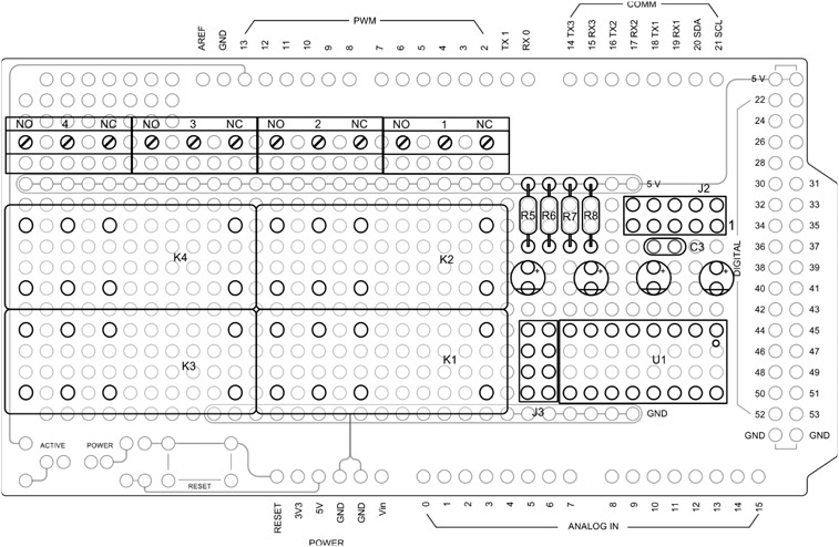
FIGURE 13-3 High current relay shield parts layout.

FIGURE 13-4 High current relay shield wiring.

FIGURE 13-5 Completed high current relay shield.
Panel Meter Shield
There is one consideration for the panel meter shield. Remember that the meter shield measures 0–1 mA DC. The potentiometers used in the rotators don’t necessarily generate a 0–1 mA signal. Rather, they are typically a higher voltage that is scaled to be read by a 0–1 mA meter on the control box. Chapter 5 included a section on how to add scaling circuits to our panel meter and we make use of that information here. For the rotators we tested, it is a simple matter to measure the voltage from the heading potentiometer at the rotator control box and use that measurement to determine the scaling circuit values needed. Figure 13-6 shows the additional circuitry added to the Chapter 5 panel meter. The additional parts required are listed in Table 13-3. Note that we decided to use an LM358 Dual opamp rather than the LM324 used in Chapter 5 for the panel meter. Either is acceptable for this application. The design uses two opamps so the dual packge, LM358, is a good choice.

TABLE 13-3 Parts List for the Modified Panel Meter Shield

FIGURE 13-6 Schematic diagram of modifications to panel meter shield.
Referring back to Table 13-1, the voltages developed in the different rotators are 0–4.5 VDC, 0–13 VDC, and 0–25 VDC. The modifications to the panel meter shield are shown in Figure 13-6. JP1 and JP2 allow the selection of the three voltage ranges. The three voltage ranges are selected as follows:
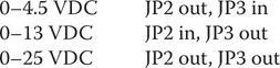
The 10K potentiometer provides fine adjustment of the meter circuit.
The modifications also include a circuit to vary the speed on the Yaesu rotators. An input from 0.5 to 4.5 VDC to the rotator varies the speed through its entire range. We have used the pseudo-analog output capability of the Arduino known as Pulse Width Modulation, or PWM, to generate a variable DC voltage that is used to vary the speed of the Yaesu rotators. By adding a simple RC circuit, the PWM output pulses are smoothed to provide a DC level with a little bit of ripple. Digital pin 5 is used for the PWM output.
Figure 13-7 shows the wiring of the modified panel meter shield. The two-position screw terminal block is replaced by one with three terminals. Figure 13-8 shows the completed modifications to the panel meter shield.
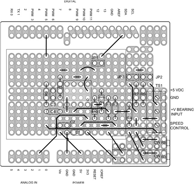
FIGURE 13-7 Wiring additions to panel meter shield.

FIGURE 13-8 Modifications completed to the panel meter shield.
The Control Panel
Some of our projects require more digital IO pins than some Arduinos can provide. For example, when you add the panel meter shields along with the relay shields and expect to have some controls to provide additional inputs, you find that there may not be enough pins! We want to use the relay shield to control an antenna rotator. This requires the use of the panel meter to sense the rotator’s actual position, an LCD to display information, a shaft encoder to set headings and several switches that are used for other functions, such as storing and recalling a preset heading. Because we don’t have enough IO pins to do all of this, we use a device called a “port expander.” A port expander device uses the Arduino’s built-in I2C bus to provide additional digital IO ports. We used the I2C bus previously in Chapter 4 to “talk” to the real time clock breakout board.
Recall that the I2C interface requires only two digital IO pins; one for clock and one for data. Using a port expander and adding power and ground, we can provide up to 16 external digital IO ports with only four wires! We constructed an external “control panel,” providing an LCD display, five switches, and a shaft encoder (also with another switch), which is connected to the Arduino through the I2C interface. Note that the shaft encoder itself does not connect through the I2C bus but the shaft encoder switch does. We use hardware interrupts with the shaft encoder so it connects to the shield on two separate wires and connects to Arduino digital interrupt pins 2 and 3.
As mentioned earlier, the control panel board is built on a prototyping board rather than a shield. It is designed to be interconnected to the Arduino shield “stack” via a 10-pin ribbon cable so that the board may be mounted remotely. The control panel board uses a Microchip MCP23017 16-port expander chip with an I2C interface. The MCP23017 provides all the digital IO ports needed to support an LCD along with six momentary contact switches (five switches and the switch on the shaft encoder). The six momentary contact switches are used for controlling multiple functions. The schematic for the board is shown in Figure 13-9 and the parts required are listed in Table 13-4.

FIGURE 13-9 Schematic of the control panel board.

TABLE 13-4 Parts List for the Control Panel Board
The control panel parts layout is shown in Figure 13-10. Note that there are components mounted on both sides of the board. The side shown in Figure 13-10 is the side facing the user and we refer to that as the front of the board. Components on the back of the board are shown with dashed lines.
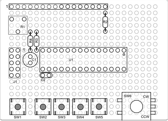
FIGURE 13-10 Control panel parts layout.
The wiring diagram, shown in Figure 13-11, shows the back side of the board and the two components mounted on this side: the pot, R1, and the header plug, J1.

FIGURE 13-11 Control panel wiring diagram.
Adding the I2C Interface to the Relay Shield from Chapter 11
One option for the Rotator Controller project is to use the relay shield from Chapter 11. An interface for the front panel board is added to the relay shield, providing connections for the I2C bus, interrupts for the shaft encoder, power, and ground.
Our I2C bus connector is a 10-pin header added to the Chapter 11 relay shield. The relay shield is assembled on a Mega prototyping shield. We placed the 10-pin header where the 40-pin IO connector would normally go. Since we are not using the 40-pin connector for this project, it seemed an ideal location. The added wiring for the front panel interface is shown schematically in Figure 13-12. Table 13-5 lists the parts required for modifying the Chapter 11 relay shield.
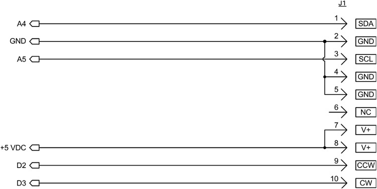
FIGURE 13-12 Front Panel interface additions to the relay shield.

TABLE 13-5 Parts List for the Modifications to the Chapter 11 Relay Shield
The location of connector J1 and wiring added to the Relay Shield is shown in Figure 13-13. The remaining circuitry for the Relay Shield is exactly as depicted in Chapter 11, and for clarity is not shown in the drawing. The Control Panel interface, J1, provides connections for the I2C bus, the shaft encoder, 5 VDC, and ground.

FIGURE 13-13 Adding the control panel interface to the Chapter 12relay shield.
Connecting the Rotator Controller
Now that you have the controller completed, it is time to hook it up and test it out. Most rotators and control heads follow a similar design concept. The rotator consists of a bidirectional drive motor, a brake, and a device to determine the direction the rotator is pointing. The control head contains a power source, a direction indicator, and switches to control braking and direction of rotation. You need to have the schematic diagrams of your rotator and control head to connect the Rotator Controller. The following sections describe how to connect to the rotators we have listed. The methods described are adaptable to rotators that are not listed. Refer to the schematics of your rotator if it is not one of the models we list. One of the schematics presented here is likely similar to yours.
Early Cornell-Dublier Electronics (CDE) Models
Early CDE models include the TR-44 and Ham-M rotators. The TR-44 and Ham-M present a unique problem. As shown in Figure 13-14, the only time voltage is applied to the heading potentiometer is when the control levers are used. This led to a design change in later control heads where there is a power switch allowing the voltage to always be applied to the potentiometer. If you are using a TR-44 or Ham-M rotator and would like to use this design for control, the rotator’s control box must be modified to always apply the voltage to the pot when it is in use, just as in the later CDE, HyGain, Telex, and MFJ models. Making these modifications requires opening the control box, adding some wiring, and in the case of the TR-44, an extra switch. (The fourth relay can be used here as well but will require an addition to the software to energize it.)
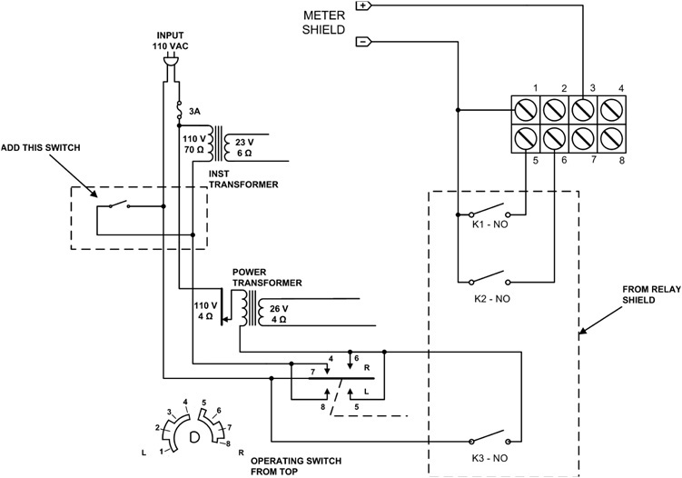
FIGURE 13-14 Interconnections for early CDE rotators: TR-44 and Ham-M.
Controlling the CDE rotators requires the higher current relays used on the Relay Shield described in this chapter or when using the Relay Shield from Chapter 11, external higher-current relays must be used.
Later Models from HyGain, Telex, and MFJ
These include the Ham 2, Ham IV, and Tailtwister T2X rotators. As shown in Figure 13-15, one set of connections is made inside the control box, placing relay K3 in parallel with the brake switch. The brake switch is the center switch of the three lever switches and is identified as S3 on their rotator schematic. The direction control relays are connected between the ground screw terminal (1) and the direction control screw terminals for clockwise/right (5) and counterclockwise/left (6). The voltmeter input (for heading) is connected between the ground terminal (1) and terminal 3.
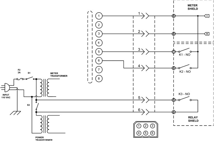
FIGURE 13-15 Interconnections for later rotators: Ham-2, Ham-IV, and T2X.
Controlling this set of rotators also requires the higher current relays used on the relay shield described in this chapter, or when using the relay shield from Chapter 11, external higher-current relays must be used.
Recent models of the HyGain control heads use an 8-pin Cinch-Jones connector, rather than a barrier terminal strip, to connect to the rotator. In this case, we used a chassis-mounted connector on the rear apron to make the internal connections to the control head. The connector used is a Molex 03-09-1061 receptacle, rated at 11 A per pin, more than enough to operate our rotator. If you do use a different connector, make sure that it has ample current rating for your application. Figure 13-16 shows our installation on a HyGain TailTwister rotator control head.
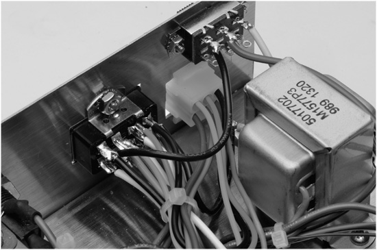
FIGURE 13-16 Installing the rotator controller interface on a late model HyGain TailTwister.
Yaesu Models G-800SDX/DXA, G-1000SDX/DXA, and G-2800DXA
These Yaesu models include a rear-panel connection for external control. The models with the “DXA” suffix use a 6-pin Mini-DIN connector for connections. The connections are described in Figure 13-17A. External connections to the rotators with the SDX suffix can be accessed through a grommeted hole on the rear panel. There is an 8-pin header on the circuit board with connections as described in Figure 13-17B.

FIGURE 13-17 Interconnections for Yaesu DXA and SDX rotators.
In all of these examples of Yaesu rotators, the relay shield from Chapter 11 is sufficient for control without changing the relays.
Software
Actually, there are two pieces of software for this project. The first piece of software is the Arduino sketch used to control the hardware and the rotator. The second piece of software is a Windows program that allows you to enter in your QTH, and, once entered, it determines your longitude and latitude. From there, you can enter any of 330 amateur radio call sign prefixes from around the world and the program gives you a beam heading for that prefix. You can also print the list out so you can use the heading specific to a given location without the use of a computer.
Arduino Beam Heading Software
LISTING 13-1 presents the code for the software that controls the hardware. There are a large number of #define preprocessor directives, many of which are shared with the DDS VFO discussed in Chapter 16. The reason is because the VFO and the rotator control use virtually the same control shield for the LCD display, encoder, and switches. We concentrate on the directives that are germane to this chapter.
The first important #define is for INITIALIZEEEPROM, which appears around line 16 in Listing 13-1. The first time you run the software, you should compile this code with the comment characters (//) removed so the directive is compiled into the program. The reason for uncommenting the line is so the following two statement blocks are compiled into the program.
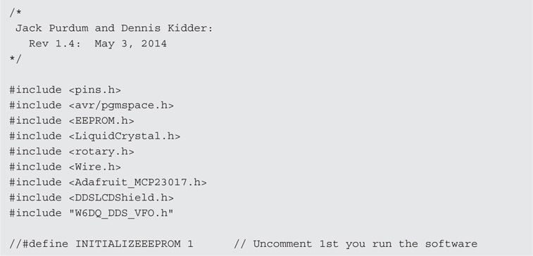


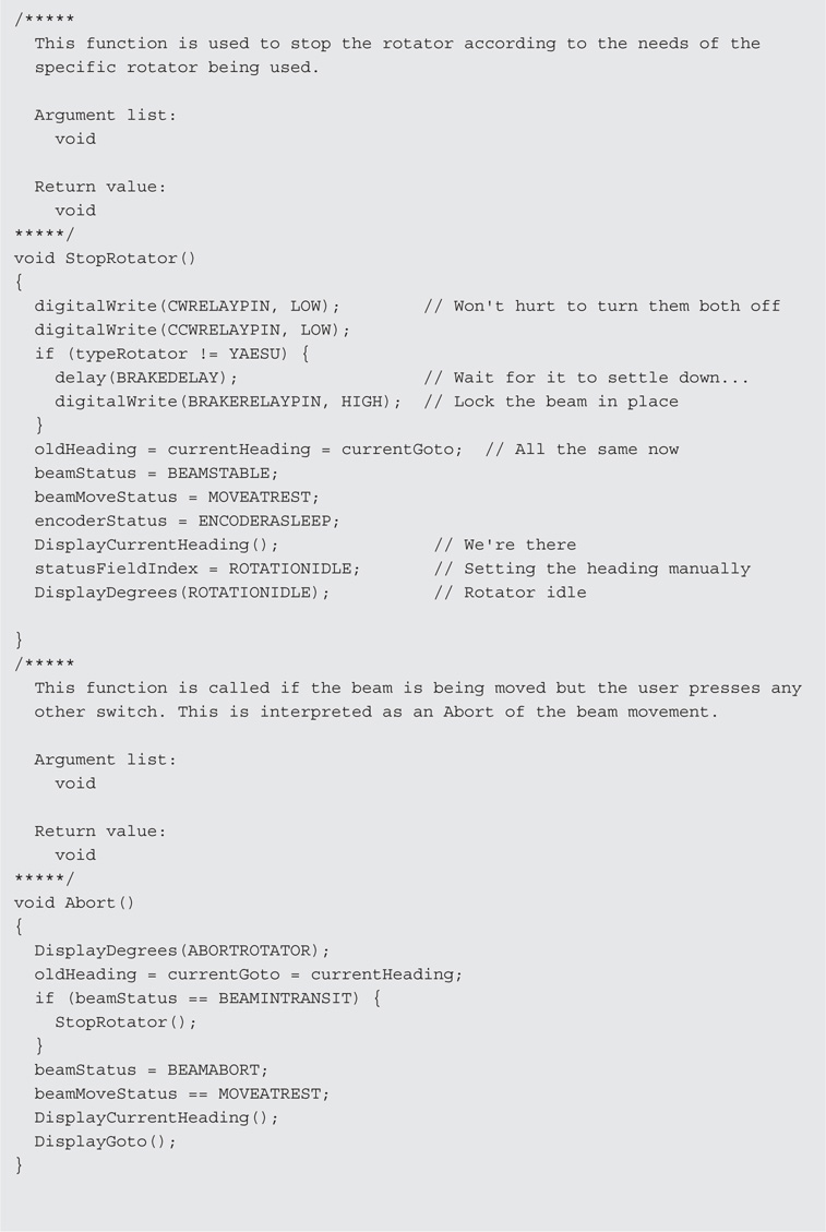

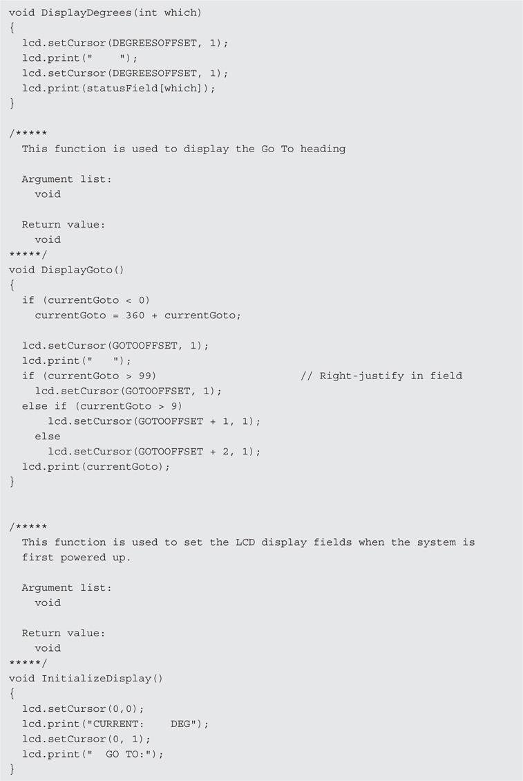

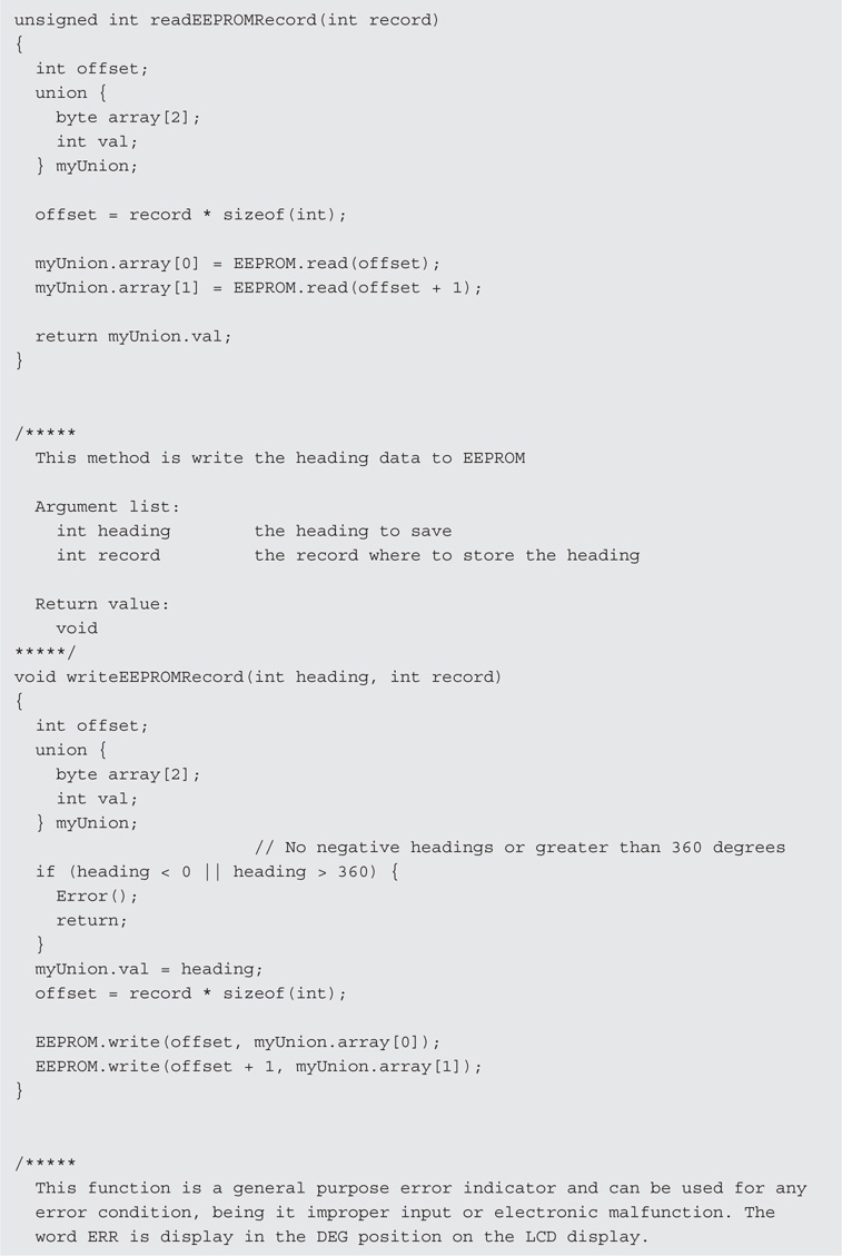

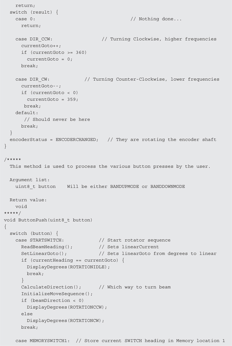
LISTING 13-1 Rotator control software.
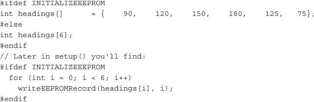
By uncommenting the #define preprocessor line, you initialize several EEPROM values that you can use to test the software. Once you have run the program one time, comment out the #define INITIALIZEEEPROM line so that it is no longer compiled into the program. When you run the program a second time, you can change our test values to whatever you wish them to be. We explain the process a little later in this chapter.
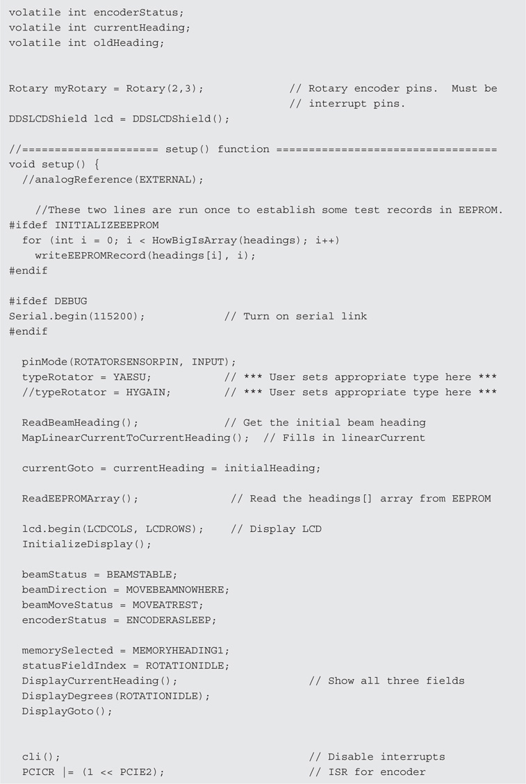
Also found in the setup() function is the statement:
typeRotator = TEST; // *** User sets appropriate type here ***
Again, the TEST symbolic constant can be used to test the code in general terms. You should, however, replace the TEST symbolic constant with the name of your rotator (e.g., CDE, HYGAIN) from the list of rotators described in the list of symbolic constants labeled Rotator Type. The rest of the setup() function code initializes a number of working variables for the program and should look pretty familiar to you by now.
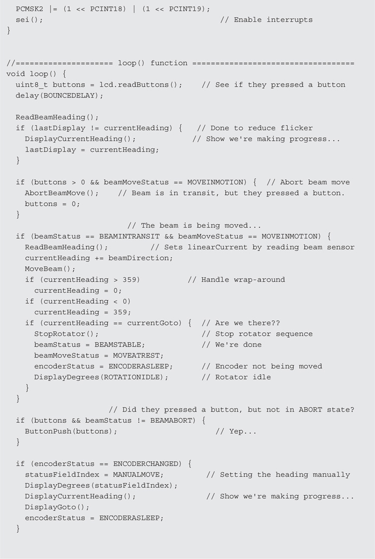
Moving the Beam
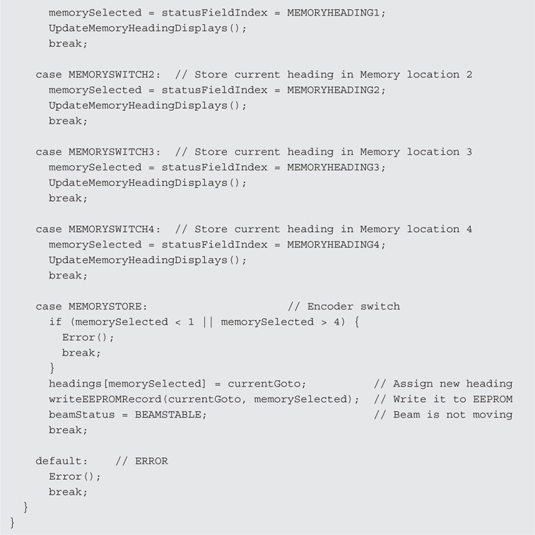
The loop() function constantly polls the controller shield hardware looking for a switch press or encoder rotation. The readButtons() method of the lcd object monitors the switches and, when one is sensed, ButtonPush() is called. There are five switches on the controller shield plus the encoder switch, as shown in Figure 13-10. SW1 is used to activate the rotator and move to a new heading. The next four switches (SW2-SW5) control the EEPROM memory addresses (MEM1-MEM2) where you store the headings that you wish to save for later recall. For example, if you look near the top of Listing 13-1, you’ll find the statement:
![]()
which are the sample headings that get stored when you first compile the program. (That’s what the symbolic constant INITIALIZEEEPROM was all about.) Figure 13-18 shows the three fields used on the LCD display. The second time you run the program, you will see the LCD display with the CURRENT and GO TO fields filled in with the number 90 and the DEG field displays CUR. The interpretation of the three fields is that the beam is currently on a heading of 90 degrees, the position to move the beam is to heading 90 degrees, and that is the current position. If you look at the headings[] array, you can see that its value is 90, which is the number you are seeing in Fields 1 and 2 in Figure 13-18. Therefore, headings[0] corresponds to the current heading.

FIGURE 13-18 The three LCD display fields.
If you press switch SW2, that switch is tied to MEM1, or memory heading 1 as stored in EEPROM. If you look at the test headings we wrote to headings[] the first time you ran the program, you can see that headings[1] has the value 120. The instant you press SW2, the GO TO field is filled in with 120 and the DEG field has MEM1 displayed immediately below it in Field 3. The CURRENT field still shows 90. The reason is because that’s the current heading of the beam.
If you wish to move the beam from its CURRENT heading (90) and GO TO the heading stored in MEM1 (120), touch the Rotate button (SW1). As soon as the rotator brake is released and the beam starts to move, the CURRENT field starts to count up from 90 and stops counting when it reaches 120. In the sequence you just performed, you moved the beam from its current heading of 90 degrees to a new heading of 120 degrees, which you had previously stored in EEPROM at position MEM1.
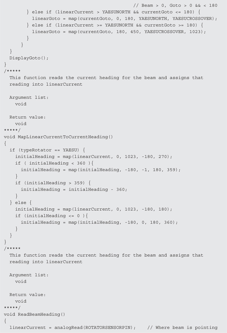
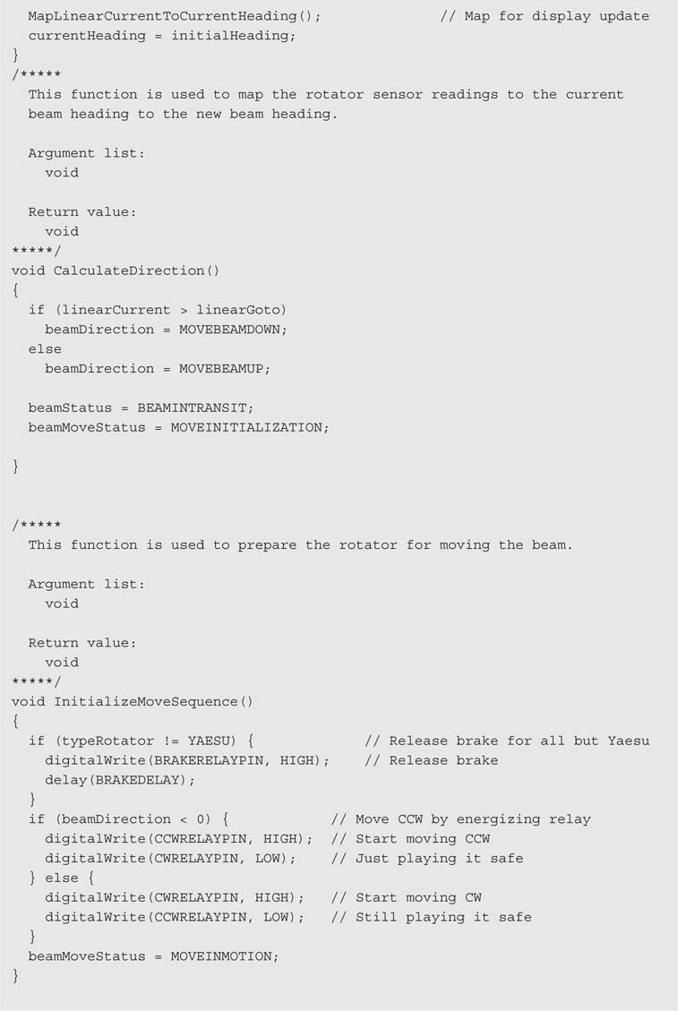
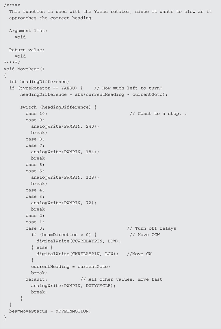
When you performed the move from 90 to 120 degrees, the call to ButtonPush() used a switch-case statement block to: 1) set the proper parameters for the calls to DisplayDegrees(), 2) which updates the DEG Field, DisplayGoto(), 3) which updates the GO TO Field, and 4) call DisplayCurrentHeading(), which updates the CURRENT heading field. The call to CalculateDirection() determines the best way to reach the new heading and MoveBeam() controls how the beam is actually moved.
If you press switches SW3-SW5, you call up the headings stored in EEPROM at locations MEM2 (150), MEM3 (180), and MEM4 (125). The instant you touch one of the heading switches, its associated heading immediately appears in the GO TO field and the DEG field is updated to reflect the memory heading you selected (e.g., MEM3). The CURRENT field does not change, as it is always used to show the current heading of the beam. If you had touched SW4, CURRENT would still be at 120, GO TO immediately changes to 180, and DEG changes to MEM3. Touch the Rotate switch, SW1, and the beam starts to move to the new heading and the CURRENT field is updated accordingly.
Setting a New Heading
Obviously you need the ability to move the beam to more than four headings. Suppose you had previously moved the beam to MEM3 with a heading of 180 degrees. Now you want to move it to 160 degrees, which is not one of your stored headings. Simply rotate the encoder shaft counter-clockwise (CCW) and the GO TO field displays the numbers decreasing from 180 down to 160 as you rotate the encoder shaft in the CCW direction. Once you have set the GO TO field to 160, touch the Rotate switch (SW1) and the CURRENT field decreases from a heading of 180 to 160 as the beam turns to the new heading.
Storing a New Heading in EEPROM
Suppose you wish to replace one of the previously stored headings with a new one. To change any MEMn heading, press the switch associated with that memory heading. The code immediately updates the GO TO field with the heading that is currently stored at that address and the DEG field changes to display MEMn. Now rotate the encoder shaft to the new heading you wish to save as seen in the GO TO field. When the desired heading is set in the GO TO field, press the encoder shaft to engage the switch that is built into the encoder. The new heading is now stored in MEMn.
For example, suppose you wish to change MEM4 from its current value of 125 to its replacement value of 110. First, press the SW5 switch, which immediately updates the DEG field to MEM4 and the GO TO field to 125. Now rotate the encoder shaft in the CCW direction until you see 110 in the GO TO field. Now press the encoder shaft switch. The new heading is now stored in MEM4. You can verify the change by pressing some other MEMn switch, which changes the DEG and GO TO fields, and then press the MEM4 switch. You should see the new heading you just entered.
World Beam Headings
The program discussed in this section can be used to create a list of beam headings for 330 call districts around the world. There is good news and bad news associated with this program. First, the good news.
The program first asks you to enter the location of the antenna for which the headings are to be calculated. Once that location is entered, the program then can be used to determine the beam heading for any one of the 330 worldwide call districts as determined from the QTH location that was entered.
The bad news is actually twofold: 1) the program only runs on Windows, and 2) the program must be run on a system that is connected to the Internet. The reason for the first limitation is that the code was developed with Microsoft’s Visual Studio using C#. The second limitation arises because the code uses the Google Maps Application Programming Interface (API) as a Web service to determine the longitude and latitude coordinates for the location you type into the program.
Finding the Coordinates for a QTH
Using the Google Maps API has a number of advantages, but the biggest in this instance is the ability to determine the exact coordinates of wherever you might choose to operate. For example, suppose you wanted to operate a Field Day station from the Wayne National Forest in southern Ohio. Even though you don’t have an address per se for the forest, you can easily determine its coordinates using Google maps.
First, load Google maps into your browser using the https://maps.google.com URL. When the map program finishes loading, drag and center the map on the approximate location where you’re going to set up your Field Day operation. For our example, when you see Wayne National Forest displayed on the map, click on your best approximation of where you will be operating. Now right-click on that location and the address bar in the upper-left side of the display pops up with the address of the location you selected (e.g., 27515 Ohio 7, Marietta, OH). Immediately below that address are the longitude and latitude for the location you selected (39.592886, –82.202334). You can use either the address that is displayed or the exact coordinates as input into the Windows program.
Figure 13-19 shows how the World Beam Headings program appears when you first load and run it. You can enter the address or coordinates into the textboxes shown in the Home QTH group box. In Figure 13-20, we got lazy and just entered Wayne National Forest into the Address textbox and clicked the Calculate Coordinates button, and the coordinate textboxes were filled in from the coordinates supplied from the Google Maps API. If you click on the Save Coordinates button, the information you see displayed is saved to a disk file so that the next time you run the program, those coordinates are automatically filled in. This means that, if you reload the program a second time, you don’t need to go through the steps to determine the coordinates used in the program.

FIGURE 13-19 World beam headings initial screen.

FIGURE 13-20 Display after entering Wayne National Forest and clicking Calculate Coordinates.
Finding a Beam Heading
Suppose you hear the call T2B on the air and you want to set your beam to the heading for T2B. Since most people don’t know where a T2 ham is operating from, you can type “T2” into the Call Sign Prefix and click the Calculate button. The display immediately changes to that shown in Figure 13-21. The program tells you that the beam heading from the Wayne National Forest to Funafuti, Tuvalu, is 268.601478829149. Because the Rotator control program doesn’t have that much granularity for a beam heading, use the encoder to rotate to a value of 269 and press the Move switch. Your beam is now pointing toward Funafuti, which is the capital city of Tuvalu.

FIGURE 13-21 Display after entering a Call Sign Prefix and clicking Calculate.
This example points out a number of important factors about the call search program. First, once you’ve set the Home QTH parameter, the beam heading look-up process is extremely fast. Simply enter the prefix and click Calculate. Second, in all cases, the heading is calculated for the capital city of the call area being searched. Our feeling is that there is no need to set the exact coordinates for the QTH of the station you are calling. There are two exceptions to this rule. The first are call prefixes for Canada. Because of their close proximity to the United States, coordinates are based on the capital cities of the Canadian provinces. Likewise, any US call points to Washington, DC. If you have problems figuring out the approximate heading for a US call prefix, you need to spend a little more time with a map.
Tom Epperly (NS6T) has a nice web site (http://ns6t.net/azimuth/azimuth.html) that allows you to create a custom world map centered on your own QTH coordinates. Once you type in your longitude and latitude (which you obtained earlier from Google maps), the map is drawn with the compass points clearly marked on the edge of the map. You can print the map, which gives you a better idea of where the output of our World Beam Heading program is pointing your beam.
A side benefit of this example is that you now know approximately where Tuvalu is …somewhere in the Pacific. Why is this important? Well, first, is because most people don’t have a clue where Tuvalu is. Second, Funafuti is a really awesome name for a city. Third, because of its location relative to the International Dateline, Tuvalu is the first country in the world to celebrate New Year’s Day. You’d be surprised how often people ask: “I wonder what country is the first to celebrate New Year’s Day?” Now you know, which may give you Phone-a-Friend status.
Finally, if you wish, you can click on the Print Bearing List, which prompts you to enter a file name to hold the output data. This action creates a text file that contains all 330 call prefixes, the country and capital city, and a beam heading relative to the QTH displayed on the screen at the time the list is printed. You can print this list out with any text reader and have a heading list that you can use when a computer isn’t handy. The list is printed in ascending sorted order.
Conclusion
In this chapter you built a shield that can help you determine, set, and rotate an antenna beam to a specific heading. We feel that this beam control system is a little easier to use than some beam controllers plus it gives greater granularity in terms of setting a heading. Finally, it allows you to easily store up to four headings that you use often, perhaps to check into your favorite net.
Of course, there is always room for improvement. Some might find it useful to have more than four preset headings. You could add additional heading switches and modify the hardware/software accordingly. More than likely, however, this would require you to mount the switches “off board” since most of the real estate on the board is already taken. A very ambitious project would be to interface the controller with a small LCD graphics display. This would allow you to display a polar plot of the world centered on your QTH like the NS6T program, with a shaded “wedge” that radiates outward from your location in accordance to the current beam heading. Another possibility is that you have a rotator that is not on our list and you modify the hardware/software interface for that rotator. We’re sure you can think of other improvements you might make. Again, we hope you will share your work with the rest of us.