
CHAPTER 4
Managing Bills and Routings
Management in a manufacturing plant or a distribution center is all about utilizing resources effectively. You have a product to deliver in a certain amount of time that consumes some materials, manpower, and machine time and can be produced using one or more methods.
Materials represent both the direct raw materials and indirect materials such as lubricants and coolants that are used during the production process. The manpower and machine resources perform the work in producing your products. The method resource is a collection of operations that in turn contain the manpower and machine resources; it allows you to model different ways of producing a product.
Before deploying these resources, you should define these resources. Oracle Applications allow you to accurately model these resources and the corresponding constraints. Figure 4-1 shows the different types of resources that exist in such environments.
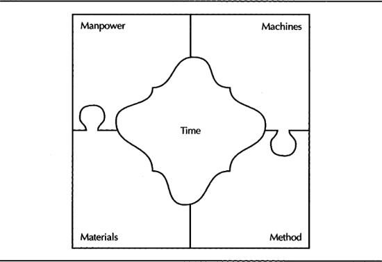
FIGURE 4-1. Resources in a Manufacturing/Distribution environment
This chapter focuses on these five resources and explains how to define and maintain these resources in Oracle Applications.
Materials
When you manufacture a product, you use raw materials or purchased components. These raw materials are just one type of a resource that is consumed by the finished product. You can produce a product from a variety of different combinations of raw materials. Oracle provides you with the capability to define all the material requirements using primary and alternate bills of material for a finished product. The components of an item have a set of attributes. For example, you can define the default source location for a component. This section explains the bill of materials feature.
Bill of Material Setup
Before you define a bill of materials for items, you should define the parent items and components as items. Item management was covered in Chapter 3. This section discusses the setup of Alternates and the item attributes that control the behavior of an item in the bill of material (BOM).
Alternates
Oracle enables you to create alternate versions of your bills of material and routings to represent the different ways to build a product. For example, if you want to keep a copy of the design bill, you might create an alternate called As Designed and use it to define a separate copy of the bill before it is changed for manufacturing purposes. Or, you might want to represent alternate methods of manufacturing an item or a set of alternate components; you can define these alternatives as alternate bills and routings, and Oracle Advanced Supply Chain Planning can use its optimization logic to pick the appropriate bill and routing.
NOTE
ASCP will only choose alternate bills and routings in pairs—i.e., for ASCP to recommend using an alternate routing, there must be an alternate bill with the same designator (even if it is identical to the primary bill).
You create the names you will use for alternates in the Alternates window. You can later on reference an alternate in both bills and routings. Bills and routings (covered later in this chapter) can share alternate labels.
Item Attributes—Bills of Material Attribute Group
The Bills of Material Attribute Group enables you to define the behavior of an item in Oracle Bills of Material and Oracle Engineering. BOM Allowed identifies whether the item can be part of a bill of material; this attribute is a status attribute.
NOTE
BOM Allowed should be yes for an item to have a bill of material as well as to be part of a bill of material.
The BOM Item Type identifiles the item’s type of bill of material. An item’s BOM Item Type can be one of the following:
![]() Standard A standard item represents a product, service, or component. (Phantom items are also classified as standard items.)
Standard A standard item represents a product, service, or component. (Phantom items are also classified as standard items.)
![]() Option Class An option class represents an option group and has a collection of options as its components. Options can be either standard items or other option classes.
Option Class An option class represents an option group and has a collection of options as its components. Options can be either standard items or other option classes.
![]() Model A model is used to represent a configurable ATO or PTO product.
Model A model is used to represent a configurable ATO or PTO product.
![]() Planning A planning item is a conceptual grouping of items and is used to distribute demand when you know the overall demand for a group of items and when you’re reasonably sure about the share of each of these products in the overall demand. For example, if you know that the demand for your personal computers would be $2 billion in 2003, you can distribute the demand to the individual products by using a planning bill.
Planning A planning item is a conceptual grouping of items and is used to distribute demand when you know the overall demand for a group of items and when you’re reasonably sure about the share of each of these products in the overall demand. For example, if you know that the demand for your personal computers would be $2 billion in 2003, you can distribute the demand to the individual products by using a planning bill.
![]() Product Family A product family is a grouping of items that are planned and produced together. When you design a line, you define it for a family and not for individual products.
Product Family A product family is a grouping of items that are planned and produced together. When you design a line, you define it for a family and not for individual products.
The Base Model identifies the model item based on which a configuration item has been defined. This attribute is applicable for Assemble to Order/Pick to Order items only. Effectivity Control enables you to identify the type of effectivity control that is applicable in your environment—date or model/unit effectivity. Model/unit effectivity is available only if you have Oracle Project Manufacturing.
Bill of Material Types
From a manufacturing standpoint, every unique assembly has its own material requirements. When an item is configurable, you have to define a model item to represent the configurable end item and option classes to represent the option groups. If you have a family of items, you have to define a product family item to represent this family during manufacturing planning and for the purposes of designing production lines. The item attribute BOM Item Type is used to identify the BOM Type of an item.
Access Control by BOM Type
You can control access to bills of material by item type using the profile options—BOM: Standard Item Access, BOM: Planning Item Access, and BOM: Model Item Access. These profiles indicate if you can create and update bills for the associated item type, but they don’t control queries. A user can query all types of bills, even without access to maintain those bill types.
Phantom Subassemblies
A phantom assembly is a non-stocked assembly. You can use phantoms to represent the intermediate subassemblies that are created during the production process. Items are designated as phantoms by the value of their WIP Supply Type, but you can override this value for a component in a bill of material. A component can represent a phantom subassembly for one parent item and a stocked subassembly for another parent item.
In general, phantom assemblies behave like normal assemblies when they represent a top-level assembly, such as when you master schedule them or manufacture them using a discrete job. As a subassembly, however, they lose their identity as distinct assemblies and are a collection of their components. The components of the phantom subassembly are included on the job and on the pick list of the job—not the phantom itself.
You can define routings (covered in the section “Method”) for phantom assemblies. Oracle WIP automatically explodes through phantom assemblies and ignores their routings when you define discrete jobs or repetitive schedules. In the BOM Parameters window, if you set the Replace with Sequence to No, the individual operation sequence numbers for phantom subassemblies will be retained. If Replace with Sequence is Yes, the phantom components will inherit the operation sequence from the parent assembly. If you set the Use Phantom Routings BOM parameter as Yes, all the phantom assembly resources and overhead costs will be charged to the parent or higher-level assembly.
Defining a Bill of Material
A Bill of Material (BOM) contains the first-level component information of an item. Other than the components, a BOM can have attachments and descriptive elements. Each standard component on a bill can have multiple reference designators and substitute components. You can create a bill from scratch, copy an existing bill, or reference a common bill. When you create a BOM, the BOM is specific to the current organization. To use a bill in another organization, you must either copy it or reference it as a common.
You create a BOM using the Bills of Material window. You must select a parent item for which you are creating the BOM; you can choose an alternate if you are defining an alternate bill. Bills and routings share alternate labels. If you create an alternate bill with the same label as an alternate routing for the same parent item, components are assigned to operations on the alternate routing instead of the primary routing. If there is no routing with the same alternate label, components are assigned to operations on the primary routing.
NOTE
You must define the primary bill or routing before you can define an alternate.
If you are updating or viewing a bill, you can view all the components, only the current components, or both the future and current components effective as of the revision date you specify by choosing an appropriate value in the Display field. If you only want to see the implemented components, check the Implemented Only field. That will exclude pending ECO changes.
BOM Components
A bill contains many components, which are items as well. Table 4-1 identifies the components that can be assigned to a parent, based on their BOM item types.

TABLE 4-1. Parent BOM Types versus Component BOM Types
A component can be included many times in the bill, provided that each entry has a different operation sequence or has a different non-overlapping effectivity.
Component Attributes
The component item sequence will default based on the BOM: Component Item Sequence Increment profile option. You can override the default value with a sequence that is unique within the bill.
You can identify the quantity that is required to make one unit of this assembly at the associated operation. This can include negative or decimal values, with a few exceptions. Pick-to-Order bills cannot have fractions if Oracle Order Management is installed. Pick-to-Order option class components cannot have negative values.
Components with Check ATP turned on cannot have negative or zero quantities. If the component has Quantity Related reference designators, then the component quantity cannot be fractional or negative.
NOTE
Negative component quantity usually indicates a byproduct.
Revision displays the current revision of the component as of the revision date of the parent item. You can specify the effective date range for this component in the Effectivity tab. The Implemented check box indicates whether the component is implemented through an ECO or if it is pending on an ECO.
The planning process uses Planning Percent for Planning Bills, Product Families, Models, and Option classes to calculate the component requirements of an item. Yield is used to represent the expected loss of a component during the production of an item. You can include the component in cost rollups. If included, the material cost of this component is included in the cost of the parent item.
You can enter the Supply Type, Supply Subinventory, and the Locator in the Material Control tab. These values default from the item attributes based on the profile option BOM: Default WIP Supply Values for Components. If set to Yes, the item attribute values are physically copied into the bill of material. You can change them if necessary, but the BOM values will take precedence over the item attributes—if you subsequently change the item attribute settings, the BOM values will not change. If the profile is set to No, you can leave the attributes blank in the BOM, and WIP will read these values from the item attributes.
For model, option class, and kit bills, you can specify the minimum and maximum sales order quantities in the Order Entry tab. You can disable ATP Check of a component in this bill if it is already enabled by the components item attribute. Indicate whether the component is optional and mutually exclusive.
NOTE
The flag Mutually Exclusive is applicable only to Option classes. The flag is set at the option class level, and it indicates if the options within the Option class are mutually exclusive during the configuration process.
In the Shipping tab you can indicate if the component should be listed on shipping documents, required to ship, or required for revenue.
Substitute Components
You assign substitutes in the Substitute Components window that you can access by clicking the Substitutes button from the Bills of Material form. You can select a substitute item and enter the quantity of the substitute item that is needed to replace the full component quantity. This quantity can differ from the quantity of the bill component.
Oracle Work in Process does not consider substitute items in its pick lists. Oracle ASCP will plan for substitutes if your constraints are set up appropriately. Advanced Planning is covered in Chapter 11.
Global Substitutes versus Local Substitutes
If an item is a substitute of another item irrespective of the using assembly, this substitute item is called a global substitute. On the other hand, if the substitute relationship is applicable on certain assemblies, the substitute item is called a local substitute. You should define global substitutes using generic item relationships that was covered in Chapter 3. You should define local substitutes using the bill component substitutes.
NOTE
Oracle ASCP recognizes only local substitutes, and Oracle Purchasing recognizes only global substitutes.
Reference Designators
Reference designators are comments/instructions that are attached to a component. Sometimes called find numbers or bubble numbers, they often correspond to a notation on a drawing. Planning bills and model, option class, and planning components cannot have reference designators. Reference designators are sorted in alphanumeric order on inquiries and reports. You create reference designators in the Reference Designators window by clicking the Designators button from the Bills of Material window. If you check Quantity Related, the system will ensure that the number of reference designators equals the quantity of the associated component; if unchecked, you can have an unlimited number of reference designators.
You can enter the reference designator names manually or generate them automatically by choosing the Add Range or Delete Range button to open the Range window. You can enter a prefix, a suffix, and starting and ending values for the range of reference designators to add or delete. For example, if you enter NN (for Neptune Networks) as the prefix, 1 and 4 as the starting and ending values, and SW (for Switch) as the suffix, NN1SW, NN2SW, NN3SW, and NN4SW are the reference designators.
Descriptive Elements
If the parent item is a model or an option class, you can specify a list of item catalog descriptive elements in the Descriptive Elements window that you can access by clicking the Elements button from the Bills of Material form. Values are assigned to catalog descriptive elements when new configuration items are created. The descriptive element value of the chosen option is assigned for each descriptive element.
If the parent item is a model, you can only specify a descriptive element name within the catalog group that is associated with the model item. If the parent item is an option class, you can specify a descriptive element name from any catalog group. These descriptive elements are especially helpful to generate a meaningful description for system-generated configured items, as well as to catalog those items.
Defining Bill Documents
You can attach documents to bills of material using the Bill Documents window that you can access using the Attachments icon. You can attach text and files, such as spreadsheets, graphics, and OLE objects.
NOTE
Bills of Material information is stored using the tables BOM_BILL_OF_MATERIALS, BOM_INVENTORY_COMPONENTS, BOM_REFERENCE_DESIGNATORS, BOM_DEPENDENT_DESC_ELEMENTS, and BOM_SUBSTITUTE_COMPONENTS.
Copying Bills
You can save time defining new, similar bills by copying their information rather than creating them manually. You can copy a bill or routing from your current organization or from another organization that shares the item master organization. You can then modify your new bill as necessary. You can copy any revision of a primary or alternate bill or routing.
You can only copy bills between items having the same BOM Item Type attribute. The copy function only copies the single level bill. When you copy a bill across organizations, the components and substitute components on the bill you are copying from must exist in the target organization. The supply subinventories and locators are not copied in the case of cross organization bill copies.
When you copy bills from your current organization, everything is copied to the new bill including the supply type and the supply subinventories and locators. You can copy bills using in the Copy Bill/Rtg From window that you can access by choosing Tools I Copy Bill/Rtg From when you are in the Bill of Materials form.
Sharing Bills
If two or more organizations manufacture the same item using the same bill of material, you can define the bill in one organization and reference it from the other organizations. Using common bills of material, you can share bills of material that exist in your manufacturing organizations with your item master organization.
You cannot create a chain of common references. You can only reference another bill or routing as a common if it has the same alternate name assigned to it. If the current bill you are creating is a manufacturing bill, the common bill must also be a manufacturing bill. If you are referencing an assembly from a different organization, all components and substitute components must exist in the new bill’s organization.
When you define a bill for a new assembly, you can reference another assembly and organization as a common bill of material. You cannot reference another bill as a common if components already exist for this bill. You share bills using the Common Bill window that you can access by choosing Tools I Assign Common Bill.
Checking for Bill Loops
Bill loops occur when a bill is assigned as a component to itself somewhere in the multilevel structure of the bill. This is illustrated by Figure 4-2 where A is defined as a component of itself, three levels down. This will cause the planning programs (specifically the explosion process) to abort. The loop check program searches for such loops.

FIGURE 4-2. Bill loop scenario
The Check for Loops concurrent program can be submitted from the Tools menu of the Bills of Material window, after a new bill has been saved. You can also run the loop check from the menu for all or a subset of your bills of material.
Mass Changing Bills of Material
You can implement a component change across many assemblies using the mass change bills feature in Oracle Bills of Material. You can define a mass change to add, delete, or replace a component or to change other component information. You can mass change a component information in all the using assemblies or choose a subset of assemblies by item range, item category, or item type. You can mass change primary and alternate bills of material for each using assembly. You can report effective changes for all using assemblies or components. Mass changes using ECOs is covered in Chapter 5.
All the mass change actions that you enter are used to determine if the change is applicable. Let’s say you are adding component A and deleting component B in a single mass change order. This change is made only if component A does not exist and component B does exist on the selected bills. The change is applied only if both conditions are met. It’s an all or nothing transaction.
TIP
If you inadvertently performed a mass change that shouldn’t have been performed, you can reverse the effects of that mass change using another mass change.
The Entire Structure
You might want to see the extent to which a component is used across all your assemblies, especially if you want to perform a mass change or if you are embarking on a variety reduction program. If you want to understand the complexity of a product, you might want to explode the bills up to the leaf level components. These two scenarios are illustrated by Figure 4-3. Oracle provides you with two tools—Indented Bills and Item Whereused—that will help you achieve this.

FIGURE 4-3. Walking up and down the structure
Indented (Multilevel) Bill of Material
An indented (multilevel, exploded) manufacturing or engineering bill of material displays the structure of a manufacturing or engineering item. You can view the multilevel BOM using the Indented Bill of Material window that is shown in Figure 4-4. If you entered an alternate, the explosion process will search for all components with the same alternate label. In case an alternate with the same label is not found at some level, the primary is used. The explosion process then continues searching for the original alternate label. You can indicate the default number of explosion levels using the profile option BOM: Default Bill of Material Levels, though, you can override this default for an explosion, if necessary.

FIGURE 4-4. Indented BOM enables you to walk down the bill structure of an item
To view more than the basic information, you can specify the level of detail you want to see (e.g., Material Control attributes, costing information, etc.).
Item Whereused
You can view an imploded list of all the using assemblies of an item in the Item Whereused window. The level of the bill of material where the inventory item appears in the parent assembly is displayed. You can view the parent assembly details in the Item Details tab and component details of the queried item in each of the using assembly in the Component Details tab.
Bill Compare
You can compare any two bills to identify the similarities and differences between them using the Bill Components Comparison form or the Bill of Material Comparison report. Two columns of check boxes, one for assembly 1 and one for assembly 2, indicate if the component appears in the assembly. The Main tabbed region displays the item and operation sequences, the planning percent, the quantity, and whether the item is optional. You can also view other component information using the other tabs.
Deleting Bills
You can delete bills using the Delete Group functionality that was discussed in Chapter 3. Several deletion constraints are installed with Bills of Material. However, you can define custom deletion constraints. Files or objects that are attached to bills are not deleted. Instead, the association between the bill or routing and the attached file is severed. When you delete an entire bill, you delete all the components for the assembly along with their reference designators and substitute items. You can archive bill (and routing) information, but not item information.
Product Families
A product family is a grouping of products that have similar production processes. When you have your product families, you can perform material planning and design lines at this aggregate level. Typically, a chart such as the one shown in Figure 4-5 will be used for grouping your products into product families. An item can belong to only one product family. You will be able to plan based on the planning percentages and effectivity of the product family members.
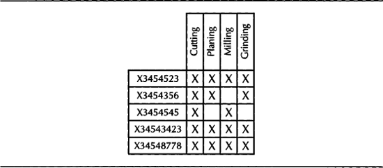
FIGURE 4-5. Create product families using a Process/Product map
Creating a Product Family
Product families are items themselves, and you can define them in the Master Items window. You can also define a product family using the Define Product Family menu. In this case, the Product Family template is automatically applied. You can designate the default template for product family items using the INV: Product Family Item Template Name profile option. The template assigned in this profile option will be automatically applied when you create a new product family item. A product family item should be an Inventory Item, and the BOM Item Type must be Product Family. The item must also be BOM allowed.
A new category is added for each product family item that is defined. The category has the same name as the product family item.
NOTE
Because each product family corresponds to an item category in the Product Family category set, the Product Family Item Categories Flexfield structure should match the structure of your System Items Flexfield.
Each product family member item and the product family item itself are assigned to the corresponding category within the Product Family category set. The assignment is removed when an item is no longer a member of a product family.
Assigning Product Family Members
The Product Family form enables you to assign product family members. You can select a product family item and choose the items that are the members of the product family. The description, type, forecast control, and planning method for the member items are displayed for the items selected.
Planning Percentages for Product Family Members
You can assign planning percentages for a member item, by clicking the Allocation button in the Product Family form. The default planning percent is 100, and the default effectivity date is the system date.
Co-Products
The co-products feature enables you to generate several end items using one primary component. Co-products are available if you have Oracle Shop Floor Management, and you use the Co-Products window to define co-products.
When you enter information in to the Co-Products window, the bills of material of the end items are automatically created. Check the Primary box to identify the primary co-product. There should be only one primary co-product for a component. Non-primary co-products are set up as common bills of material pointing to the primary co-product’s bill. The primary co-product’s bill can be an alternate or a primary bill.
You can define component details, component substitutes, and co-product substitutes using the Details, Substitutes, and Co-Product Substitutes buttons.
Oracle ASCP calculates supply for multiple assemblies based on the demand for any one of the possible co-product assemblies. The planner can generate and release planned orders for the item for which demand was realized and then view the co-product supplies being generated for the rest of the items in the co-product relationship.
BOM Business Object
You can use the BOM business object API to integrate with other software systems. The BOM business object API can be used to create or update a BOM in Oracle Applications by calling a PL/SQL procedure directly instead of using the open interface.
You need to initialize certain system information before you call the BOM API because each applications table has some system information such as the Who columns. The initialization API sets up some session variables, which is available for the BOM API. Substitute the appropriate values in the following code listing to initialize the system variables:

NOTE
The method requires a security_group_id, but you can ignore this parameter; in this case the default of 0 will be used. Security group is used to identify the reports and concurrent programs that are available to a user.
The steps for importing bills of material using the BOM business object API are as follows:
1. Construct a PL/SQL Record for the Engineering Change Order (ECO) header information, say p_eco_header of type Eng_Eco_Pub. eco_rec_type, if you want to reference an ECO header. ECO is covered in detail in Chapter 5.
2. Use Table 4-2 to construct the following PL/SQL tables for all the information that is associated with the BOM:

TABLE 4-2. PL/SQL Tables for the BOM Business Object
3. Call the procedure process_bom with the parameters that you constructed in step 2. You don’t have to supply all the parameters in every case. If you browse through the signature of this procedure in the manual, you would note that most of the parameters have a default value. So, if you were inserting a whole new BOM, you would provide all the information. On the other hand, if you are modifying a component attribute, you just provide the header and the component information:

Time
Time is money. Execution (both manufacturing and supply chain) happens in real time, but the planning activities, both long-term and short-term, are based on an estimate of available work time. Oracle Applications provide you with the ability to create these time estimates using Workday Calendars. The planning and scheduling systems use workday calendars for lead-time calculations and to calculate the total resource availability. In this section, we will discuss this feature and its components.
Workday Calendar
A workday calendar identifies the valid working days for a manufacturing organization and consists of a repeating pattern of days on and days off and the exceptions to that pattern. You can define any number of workday calendars and assign them to any number of organizations. The form Workday Calendar enables you to define workday calendars.
Calendar Attributes
The quarterly calendar type identifies how the manufacturing calendar is laid out in terms of weeks and months. The 4/4/5 Week Pattern specifies that a quarter of a year consists of two four-week periods followed by one five-week period. 5/4/4 Week Pattern specifies that a quarter contains one five-week period followed by two four-week periods. Calendar Months implies that the year has twelve periods based on calendar months. 13 Periods implies that the year contains thirteen four-week periods.
ASCP enables you to report in both weekly and period buckets if you choose 4/4/5 Weekly Pattern or the 5/4/4 Weekly Pattern as the quarterly calendar type. You can only generate reports in monthly buckets if you choose 13 Periods or Calendar Months as the quarterly calendar type.
CAUTION
You must use a 4/4/5 or 5/4/4 weekly pattern to forecast in period buckets in the planning applications; you cannot forecast in monthly buckets.
The date range identifies the start date and end date of the calendar. The default end date is four years from the start date. Days on and off are calculated based on the start date and the day of the week. So, you would typically specify a Monday as your calendar start date.
Workday Pattern
You can define a series of repeating workday on/off sequences for a given calendar. For example, if you have a work sequence where you work four days the first week (three days off) and three days the second week (four days off), you can define these in sequence. When you build the calendar, the valid workdays are automatically determined for you, based on your workday pattern. You define workday patterns in the Workday Patterns window that you can access by clicking the Workday Pattern button on the Workday Calendar form.
Workday Exceptions
You define exception templates in the Exception Templates form. An exception template enables you to create groups of exception dates and apply them to different calendars. Multiple exception templates can be applied to the same calendar. As each template is applied, new exception dates are added to the exception list for that calendar. This enables you to define different holidays or scheduled down times, for example, for organizations in different countries.
Shifts
For a given workday calendar, you can specify any number of shifts. Shifts inherit workday exceptions and workday patterns from the base calendar. Shift exceptions can either add to or override those of the base calendar. If you create a shift without first creating a workday pattern, a default workday pattern of five days on and two days off is created. You can then update that workday pattern.
If an exception on the base calendar changes, those shifts that do not have an overriding exception on that date will automatically reflect the change. Those shifts that do have an overriding exception on that date will not reflect the change and must be changed manually if they are to reflect the change in the base calendar.
You create shifts in the Shifts window that you can access by clicking the Shifts button from the Workday Calendar form. You must specify a shift number and enter the description for the shift. You can enter multiple start and stop times in the Shift Times window, but the start and stop times for a shift cannot overlap.
NOTE
Multiple start times and end times enable you to model intervals (e.g., break periods) in shifts, though it is not always necessary to maintain this level of detail.
Reviewing the Workday Calendar/Shift
Review your calendar in the Calendar Dates window (or Shift Calendar Dates window) that is shown in Figure 4-6. You can access this window by clicking the Dates button from either the Workday Calendar form or Shifts window.

FIGURE 4-6. Reviewing calendar dates
Apply exceptions to the calendar or shift by clicking the Exception List button in this window. Exceptions can be applied to the workday calendar by selecting individual exception days, by loading them from an exception template, another calendar, and another calendar shift, or by copying a set of exceptions from another calendar.
Building the Workday Calendar
When you have created a workday pattern, assigned shifts, assigned workday and shift exceptions, and reviewed your work, you must build the calendar and assign it to one or more organizations. You can build a calendar using Tools I Build when you are in the Workday Calendar form.
CAUTION
Rebuilding an existing workday calendar affects all organizations that reference the same calendar and exception template.
Copying Calendar and Shift Information
You can copy the entire calendar, including workday patterns, exceptions, and all the shifts. Or, you can just copy a specific shift, including the workday patterns, exceptions, and shift times. If you invoke Tools I Copy from the Workday Calendar, Calendar Dates, and Workday Patterns windows, all workday patterns, all exceptions, and shift information are copied. If you invoke Tools I Copy from the Shifts, Shift Times, Shift Dates, or Shift Workday Patterns window, the shift workday patterns, shift exceptions, and all shift times for the specified shift are copied.
CAUTION
If you copy calendar information to an existing calendar, all new information is appended to the existing calendar information.
Manpower and Machines
A product is manufactured using labor and machines. These are the resources that convert the raw materials into a finished product. Oracle provides you with the capability to define these resources at three levels—Resource Groups, Resources, and Resource Instances. Resources are then grouped into Departments, which represent the various workgroups in the organization. In this section, we will explain the resources, resource instances, and departments.
Resources
Resources represent anything (other than material) that you require to perform, schedule, or cost your manufacturing activities, including persons, machines, outside processing services, and physical space. Starting from Release 11i.4, Oracle enables you to define resource instances for person resources and machine resources.
When you define your departments, you assign the resources available in each department and the shifts that each resource is available for. For each operation you define, you specify a department and list of resources and usages. An operation can use any resource that is available in the department.
Resource Group
Resource Groups provide you the ability to segregate your resources into major groupings. Rough cut capacity Planning (RCCP) allows you to report by using resource groups. RCCP is covered in detail in Chapter 10.
Defining a Resource
You define resources in the Resources form. The resource name must be unique within the organization. For example, you could assign W12 to represent workman grade 12 or PP for pallet pickers. The resource type identifies if the resource is of type person, machine, etc.
Specify a unit of measure (UOM) that describes how you measure the resource. The site-level profile BOM: Hour UOM indicates the unit of measure that represents an hour. You cannot schedule resources whose units of measure are not in the same class as the hour unit of measure (UOM is covered in Chapter 15).
NOTE
You cannot update the resource UOM if the BOM: Update Resource UOM profile option is set to No. Use caution if you do change the resource UOM after you have used the resource—changing the resource UOM does not change any effected cost or routing information.
When an operation is completed, the resource units are applied to the job or repetitive schedule either manually or automatically, based on the charge type. The basis type enables you to specify if you want to specify if you want to charge and schedule the resource for each assembly or for the total job/schedule quantity. Jobs and Schedules are covered in detail in Chapter 16.
If you are performing some of the processing at a supplier site, you can model that part of the process as an outside processing (OSP) resource by checking the outside processing flag. The service itself is modeled as a combination of the resource and the associated item; you should enter an item number that represents the outside processing service for this resource. Outside processing is covered in detail in Chapter 16.
Check the Costed flag to collect and assign costs to this resource. If you are using Activity Based Costing, enter an Activity for the resource. You can use activities to group resource charges for cost-reporting purposes.
NOTE
The security functions Privilege To View Cost Information and Privilege To Maintain Cost Information control the ability to view and maintain cost information.
If the resource is costed, indicate whether to charge jobs and repetitive schedules based on a standard rate you define. If you don’t charge at the standard rate, you can maintain individual pay rates by employee and charge these rates to the job. In the case of outside processing, if you do not charge the standard resource cost, you will charge the actual PO price to the job. Variances will be posted to the appropriate rate variance accounts in this case. For costed resources, you must enter an absorption account that is used to offset resource charges earned in work in process and a rate variance account to collect the variance from charging actual rates to the job.
NOTE
The table BOM_RESOURCES stores information about resources.
For outside processing resources, the default absorption account is the receiving valuation account as defined in the receiving options; the default rate variance account is the organization’s Purchase Price Variance account. If you change the default account, your receiving valuation account will have an incorrect balance because of the two accounting transactions that are shown in Figure 4-7.

FIGURE 4-7. Accounting transactions for OSP receipt
You can define the direct costs associated with a resource in the Resource Costs window that you can access by clicking the Rates button from the Resources window. You can associate overheads with a resource in the Resource Overhead Associations window that you can access by clicking the Overheads button from the Resources window.
If a resource is a setup resource, you can identify the setup type using the Setup Types window that you can access by clicking the Setups button. This can be used for Changeover Time Reduction studies (covered in more detail in Chapter 7).
Resource Instances
Resources identify the skills that are required to perform one or more activities. This aggregate representation is very useful in planning work. When it comes to scheduling/dispatching work, you need to know the actual instance that does the work, as highlighted in Figure 4-8. This is especially true in the case of person and machine resources.

FIGURE 4-8. Work is scheduled/dispatched to resource instances
Instances of Manpower Resources
You can identify the employees who are instances of a person resource, by clicking the Employees button that will be enabled for person resources in the Resources form that is shown in Figure 4-9.

In the case of person resources, you can think of a resource as a role that many persons can play. For example, Assembly Operator can be a role, and both Jim and John can play this role. Also note that an employee can be multi-skilled. That is, Jim can be an assembly operator as well as a machine operator.
Instances of Machine Resources
You can identify the machines that are instances of a machine resource by clicking the Equipment button that will be enabled for machine resources in the Resources form that is shown in Figure 4-9.
The instances of a machine are serialized inventory items. You can select any items that have the Equipment flag enabled in the Physical Attributes group.
In the case of machine resources, you can think of a resource as a machine class. For example, a Horizontal Machining Center can be a machine class. An item can be equated to a model of a machine class. Makino-J66 is a model that belongs in this machine class. A serialized item can be equated to a machine instance. AX34535 is a serial number of the item Makino-J66 and represents an instance of Makino-J66, which is a Horizontal Machining Center.
Resource Whereused
If you want to analyze the impact of modifying a resource definition, you might want to know the operations (covered in the section “Method”) that are utilizing a resource. You can perform this query using the Resource Whereused form.
Departments
A department is a collection of resources. It can be used to represent a work group, a manufacturing cell, etc. A department consists of one or more people, machines, or suppliers and enables you to collect costs, apply overhead, and compare load to capacity. When you define a routing (covered later in this chapter), you assign a department to each operation in a routing and choose the resources that are available in that department.
NOTE
Department need not necessarily denote a physical area. It can also represent a logical collection of resources.
Department Classes
Department classes group departments and are used for reporting purposes. Department classes are created in the Department Classes form. The Departments button enables you to assign departments to a department class. You can also assign departments to department classes when you define departments.
Defining a Department
You define departments in the Departments form. When you define a department, you specify any department overhead costs and the resources that are available. A department can contain an unlimited number of resources. For each resource, you can specify the shifts that the resource is available. For each resource shift, you can also specify capacity modifications that change the available hours per day, units per day, or workdays. The department name must be unique within the current organization. You must assign a location to a department if it will likely be referenced in a routing, following an outside processing operation. Specify a project expenditure organization if you are using Project Manufacturing. You can make a department inactive by specifying an inactive date, after which you can no longer assign this department to routing operations.
NOTE
The tables BOM_DEPARTMENTS, BOM_DEPARTMENT_RESOURCES, and BOM_RESOURCE_CHANGES are used to store department and department resource information.
Overhead Rates
You can enter the department overhead rates in the Overhead Rates window that you can access by clicking the Rates button. For each cost type, specify the various overhead cost components and the corresponding rates.
Assign Resources
You assign resources to a department in the Resources window (shown in Figure 4-10) that you can access by clicking the Resources button from the Departments form. The window shows owned and borrowed resources in two sections. Each resource can be assigned to any number of departments; multiple resources can be assigned to each department.
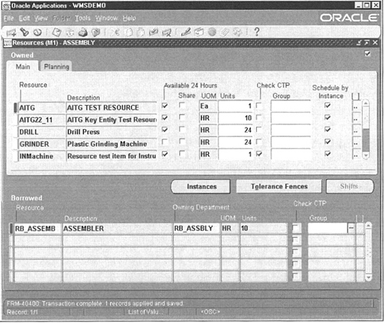
FIGURE 4-10. Owned and borrowed resources of a department
Owned Resources
Indicate whether the resource is available 24 hours a day and whether this department can share the resource and capacity with other departments. The Check CTP check box enables you to specify whether this resource needs to be included in a Capable to Promise (CTP) check. Specify a resource group for the resource in this department that will be used in Rough Cut Capacity Planning. Indicate if you want scheduling to be done at the resource instance level by checking Schedule by Instance. If this box is not checked, scheduling will occur at the resource level. Assign an exception set that will be used to identify capacity problems. Assign an expenditure type for the resource.
Department Resource Instances
If you schedule at the instance level, you can choose the resource instances that are available for this department. You cannot define new instances; the list is restricted to instances that were defined for the resource.
Tolerance Fences
Tolerance fences let you specify the rate at which you can ramp up capacity. For example, you might have no flexibility for a week or two (a tolerance of zero), but after three weeks, you might be able to increase capacity by working overtime. If you define these tolerances, ASCP can use them as part of its optimization logic; see Chapter 11.
Shifts
For owned resources that are not available 24 hours, you can assign shift information in the Shifts window that you can access by choosing the Shifts button. Choose a shift number that is available in the workday calendar that is assigned to the organization.
You can define temporary capacity changes of a resource by choosing the Capacity Changes button. Capacity modifications can add or delete a day, or add or reduce capacity for a shift. A simulation set must be associated with each capacity change. You can use this to simulate different scenarios during capacity requirements planning (CRP). CRP is covered in Chapters 10 and 11.
If you want to add or remove a workday from a shift, choose the action as Add or Delete. On the other hand, if you intend to add or reduce capacity for a resource in a shift, choose Add or Reduce Capacity. Enter positive numbers to add capacity and negative numbers to reduce capacity.
You can increase or decrease the number of resource units available in a shift by entering positive or negative numbers to increase or decrease the number of resource units, respectively.
The effective date identifies the start date of the capacity change. When you add or remove workdays, the effective start date represents the day that is being added or removed. If you are adding or reducing capacity, the start date represents the first day of the capacity change; in this case, you must also enter a date and time on which the change is no longer in effect.
Borrowed Resources
Identify the owning department for borrowed resources, and specify the number of capacity units (resource units) available for this department. Enable CTP Check and include a resource group for the resource in this department, optionally. Figure 4-11 illustrates how Borrowed Resources would be set up.

FIGURE 4-11. How to define Borrowed Resources
Method
You can utilize different combinations of manpower and machines to produce a product. For example, you can achieve an operation with a lathe or using a drilling/milling machine combination. Oracle provides you with three flavors of routings—Routing, Flow Routing, and Network Routings. Routing is part of the standard product, Flow Routings are part of Oracle Flow Manufacturing, and Network Routing is part of Oracle Shop Floor Management. Each of these three flavors is built on the same premise—a product is produced in a sequence of steps. There are some additional capabilities in Flow Routings and Network Routings. This section explains these features.
Routing
You create a routing in the Routings window. Choose an item and specify an alternate if this is an alternate routing. If you would like this routing to be used in capable to promise calculations, enable the Capable to Promise (CTP) check box.
NOTE
Only one routing for an item can be CTP enabled.
The Display drop-down list enables you to display All, Current, or Future and Current operations effective as the revision date you specify. You can enter completion subinventory and locator information or view a common routing in the Routing Details window that you can access by choosing the Routing Details button. You can copy or share another item’s routing using Tools I Copy Routing From or Tools I Assign Common Routing, respectively. If the routing is shared from another item, the source item is displayed under Common Routing in the Routing Details window.
Revisions
You can define any number of revisions for an item’s routing. Routing revisions are similar to item revisions—like item revisions, they simply point to an effective date—but they are created and maintained separately. When you create a routing, the beginning revision defaults to the value for Starting Revision in the Organization Parameters window. When you create or update a routing, you can choose to create a new revision or modify an existing revision.
Standard Operations
If your products have operations that are similar, you can define those operations as Standard Operations and use them in your routings. You can either copy or reference a standard operation when you create routings. If you copy, you can modify the operation details. If you reference, you cannot modify any of the operation details. The fields of a standard operation are exactly the same as an operation in a routing and are covered in the section “Operations.”
Standard Warehouse Tasks
Oracle WMS uses standard operations as standard warehouse tasks. If you are defining a standard warehouse task, you should identify the Task Type. The Task Type can be Pick, Putaway, Cycle Count, etc. The task assignment engine in Oracle WMS assigns each warehouse task with a standard warehouse task to identify the resource requirements of the task.
Operations
Specify the operation sequence, and optionally select an Operation Code to copy or reference a standard operation.
TIP
If you want to create a standard operation on the fly, you can do so by using Tools I Standard Operations menu.
If you are not using a standard operation, enter the department in which the operation is performed and an effective date range. You can indicate if the operation is option-dependent in the case of model/option class routings (Option dependent-operations are covered in Chapter 6).
Lead Time % indicates the percent of the item’s total lead time that is required to complete all previous operations on the routing. This value is used by planning to schedule material to arrive on the operation start date (instead of the order start date). It is calculated by the Calculate Manufacturing Lead Times concurrent program, but can be overridden.
Countpoint operations are gateways in a product’s routing and indicate whether you typically report an operation; only countpoint operations default on the WIP move transaction. The Count Point check box enables you to identify these gateway operations.
Autocharge indicates whether you always perform an operation. If you designate an operation as an autocharge operation, it is automatically completed if you skip over it, and any resource charges and material backflushing is performed as if you had explicitly completed it. You would designate an operation as a non-autocharge operation if it were a rework type of operation that you do not want to charge unless you explicitly transact it. Although they are two separate check boxes, the Count Point and Autocharge check boxes work together, and you cannot set Autocharge off if Count Point is on.
Backflush indicates whether a move transaction will attempt to backflush any operation pull material as the operation is completed. If backflushing is disabled for an operation, material will not be backflushed at that operation, even if components are linked to that operation in the bill of material. It will be backflushed when the next backflush operation is completed. (For this reason, you should make sure that the last operation in a routing has backflushing enabled.)
Theoretically, the backflush flag in the routing should correspond to assignment of material in the BOM—if you have assigned Operation pull components to a routing operation in your bills, that operation should normally be identified as a backflush operation in the routing. In practice, all operations default to backflush operations, and the default is appropriate in most cases—if an operation is designated as a backflush operation, but has no material assigned, no backflushing occurs.
You might want to designate an operation as a non-backflush operation, even if material is associated with that operation, if you want to defer backflushing to a more efficient point. If, for example, your material is actually consumed in an operation where you typically report one unit at a time, you might gain a slight performance advantage by deferring the backflushing to a later operation where you report larger quantities—you end up generating one large backflush transaction, rather than a lot of smaller backflush transactions. You should strike a balance between this performance improvement and the potential inaccuracies in inventory by not backflushing at the point of use.
The Minimum Transfer Quantity is used to specify the minimum quantity of the assembly that can be moved from this operation. You will get a warning if you attempt to move a number that is less than this value. The default minimum transfer quantity is 0.
Specify the Operation Yield for each operation. The valid values range between zero and one. This represents the percent of the assembly that is output from this operation. For example, if the operation yield is 0.9, only 90 percent of the assemblies that enter this operation are expected to make it to the next operation.
Operation Resources
Define the resources that will be used in each routing operation. Designate each resource as lot-based or unit-based using the Basis field. A lot-based resource is used only once per order, whereas the usage of an item-based resource is multiplied by the job quantity. Specify the Usage of the resource in the resource UOM. The inverse field automatically reflects the amount of resource requirement per unit of the resource UOM. For example, if the usage is 0.1 and the resource UOM is HR, the inverse will be 6. You can alternatively enter the inverse, and the usage will be automatically calculated for you.
Indicate if this resource is available for 24 hours using the Available 24 Hours flag. If you want your resources to be scheduled in a different sequence than the order in which they are defined, specify that sequence using Schedule Seq. Resources with the same schedule sequence are considered as simultaneous resources, and you can select one of the resources as a primary resource using the Principal flag.
You can associate alternate (substitute) resources to operation resource groups that have the same schedule sequence. The alternate resources have a Replacement Group number. When considering alternates, all the resources with the same replacement group will be considered as a potential replacement. For example, if you have a lathe operation that can in turn be achieved using a milling machine and a drilling machine, you can combine the milling and drilling machines as one replacement group for the lathe, in the alternate Operation Alternate Resources window. Within the alternate resources, identify the primary resource using the Principal flag.
NOTE
As in the case of items, there are global and local (within a routing operation) substitutes for resources as well. At the time of writing this book, the global substitute feature was still being designed.
Indicate the number of resource units that are required for this operation using Assigned Units.
Include or Exclude a resource when scheduling an operation and when calculating manufacturing lead-time for the assembly by setting the Schedule field to Yes or No, respectively. If you want to indicate that a resource can operate in tandem with the prior or next resource, you can achieve that by setting the Schedule field to Prior or Next, respectively. Figure 4-12 illustrates these different scheduling options.

FIGURE 4-12. Operation Resource Scheduling options
The Resource Offset % indicates the percent of time in the item’s manufacturing lead-time when this resource completes. In concept, this is similar to the lead-time percent of the operation. It is used by MRP for capacity planning to estimate the timing of resource load. Like the operation’s lead time percent, it is calculated by the lead-time calculation process or can be manually entered.
If you are using activity-based costing, identify the activity type of this resource using the Activity field. Specify if you want to collect resource charges at the standard resource rate using the Standard Rate flag. Determine how each resource is charged using Charge Type. If the charge type is Manual, you must manually charge the job or repetitive schedule. If the charge type is WIP Move, Oracle WIP will automatically charge this type of resource to a job or repetitive schedule when you complete an operation.
Use PO Receipt and PO Move as the charge types for outside processing operations if you want to charge the job when the outside processing PO is received. In both these cases, the job is charged at the receipt of the PO. The difference between PO Move and PO Receipt is that a PO Move resource charges the job and performs a move at the same time (via the open interface); a PO Receipt resource just charges the job and waits for a separate move transaction. You might use both PO Move and PO Receipt resources in a single operation (e.g. there might be a separate setup charge and a separate run charge); no more than one resource at an operation can be a PO Move resource.
NOTE
The tables BOM_OPERATIONAL_ROUTINGS, BOM_OPERATION_SEQUENCES, and BOM_OPERATION_RESOURCES are used to store information about routings.
Switching Between Primary and Alternate Routings
If you want to switch between primary and alternate routings, query the alternate routing that you want to switch to primary and choose Tools I Switch to Primary. This will make the current routing the primary routing; rename the previous primary routing with the alternate designator of the current routing, though you can specify a different alternate if you choose. This does not affect any jobs, plans, or costs that were based on the former primary routing.
Cost Rollup
You can perform a single-level cost rollup for the current routing using Tools I Rollup Cost. Specify the cost type. The effective date and time are used to determine the structure of the bill of material to use in the cost rollup. This enables you to roll up historical and future bill structures using current resource rates and component costs. You can optionally include unimplemented engineering change orders (ECO) in the rollup. (ECO is covered in detail in Chapter 5.) After the rollup is completed, the cost rollup process can optionally produce the Indented Bill of Material Cost Report, which lists the detailed cost structure by level.
Flow Routing
Flow routing is simply a sequence of events that can be organized and grouped into two views—the As Designed view (Processes) and the As Manufactured view (Line Operations). This is illustrated by Figure 4-13.
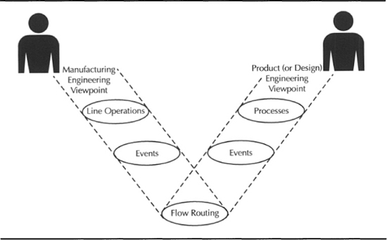
FIGURE 4-13. Flow routings provide you As Designed and As Manufactured views
Events represent the smallest unit of work in a flow line. These events identify the resource requirements and are grouped under processes or line operations. To be included in the Mixed Model Map calculations, event resources should be scheduled (any value other than No). Mixed Model Map is covered in detail in Chapter 7.
Standard Events, Standard Processes, and Standard Line Operations
Define standard events, standard processes, and standard line operations using the Standard Events, Standard Processes, and Line Operations forms, respectively. All the attributes are essentially the same, and most of them are available in the standard routing feature that was covered earlier. A significant difference is that a production line is associated with all of these. Flow routings are always defined for a combination of a product and a production line. Production lines will be covered in Chapter 7.
Flow Routing
You define flow routings in the Flow Routings form shown in Figure 4-14. Include standard processes, line operations, and their associated events. You can view the processes, line operations, and all the events in the flow routing itself by choosing the appropriate view option. However, you edit the events that are associated with a process or a line operation using the Events button.
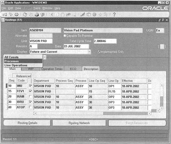
FIGURE 4-14. Associate processes and line operations to an assembly/line combination in the Flow Routings form
You use the line operations and the associated events for balancing your line. Specify the Operation Yield and the Planning Percent for each operation. You can use Tools I Calculate Operation Yields to calculate the Cumulative Yield and Reverse Cumulative Yield. The operation yield plays a significant role in line balancing decisions. Line balancing is covered in Chapter 7.
Routing Network
When you have your processes and line operations, you must specify the network of processes through which the item is routed. This includes specifying alternate processes, planning percent, rework loops, rework percentage, and feeder lines.
You define routing networks in the Routing Network Designer window that you can access by clicking the Routing Network button from the Flow Routing form. Choose to view either Processes or Line-Operations by selecting the appropriate tab. When in the window, all the processes or line operations are listed in a tree on the left side. The routing network is graphically represented on the right.
Link two processes/line operations by choosing the Connector button at the top of the screen and clicking and dragging the Start node to the destination node that you are linking. You can define the link details in the pop-up window that appears when you define a relationship.
The events that are yet to be associated with a line operation/process will be listed on the bottom left of the screen. You can associate an event with a process/line operation by dragging the event to a process or line operation. You can drill down into a process or line operation to view the events that make up the process/line operation, and you can move events from one another by dragging and dropping.
Network Routings
Network routings comprise a collection of routing operations that include primary paths and alternate paths and allow flexible routing for lot-based jobs. This type of routing is used in scenarios where the paths that jobs take are not always known at the time the job is created.
Network routings use only standard operations; therefore, you must define all the possible operations as standard operations. Define the network routing for an item in the Routings form. This routing should contain all the possible operation paths.
The network routing is really an extension of the standard routing. All the attributes of the standard routing are available in the network routing as well. There are a few additional attributes such as the cumulative and reverse cumulative yield.
The major extension, however, is the routing network. The network relationships between the different operations and the sequence of operations are defined in the Routing Network window that you can access by clicking the Routing Network button in the Routing form. This button will be enabled only in Shop Floor Management enabled organizations. In this window the primary and alternate paths are outlined along with the percentage; each is likely to be used. Although the number of paths from start to end could be numerous, there must be a unique starting operation and a unique ending operation in the entire network.
Define your routing network by entering the operation sequence and the values From and To in the Code fields. Identify the primary path with the Link Type field. The primary path should be a complete chain of operations from start to finish. The Planning % indicates the percentage of material flow through each operation.
NOTE
The operation relationship in the routing network is defined using operation codes. This is the reason network routings mandate you to use standard operations.
When a complete network routing is defined, a WIP Job for a Lot begins with a routing comprising only the first and the last steps. As the job completes the first step, you select the next operation in the network. The process continues until the job reaches the last step when the job is completed.
Logical Data Model of Manpower, Machines, and Methods
Figure 4-15 will help you to reinforce your understanding of the various entities that constitute the method definition in Oracle Applications and the relationships between them.

FIGURE 4-15. Logical Data Model of Manpower, Machine, and Method Definitions
Although the figure implies operations, events, and standard operations have relationships to both departments and resources separately, the relationships need to be looked at collectively. We always select a department before selecting a resource in the operation (or event) resources form. Also this is a many-to-many relationship and is resolved by the table BOM_OPERATION_RESOURCES in the physical data model.
Routing Business Object
You can use the Routing business object API to integrate with other software systems. The routing business object API can be used to create or update a routing in Oracle Applications by calling a PL/SQL procedure directly instead of using the open interface. Initialize the system (as explained earlier) and follow these steps:
1. Construct a PL/SQL Record for the Routing header information, say p_rtg_header of type Bom_Rtg_Pub.Rtg_Header_Rec_Type.
2. Construct the following PL/SQL Tables for all the information that is associated with the routing:

3. Call the procedure process_rtg, with the parameters that you constructed in step 2.

Summary
This chapter identified the types of resources (materials, manpower, machines, methods, and time) in a manufacturing environment. Bills of material and co-products represent the material resource. You can define alternate bills to represent the different groupings of raw materials for a particular item. A number of the attributes at the item level are also available at the bill component level.
Workday calendars and shifts allow you to model the Time resource. You can model complex workday patterns using the workday calendar. For example, you can create a pattern that has four days on and three days off in the first week and three days on and four days off in the following week.
The manpower and machine resources allow you to model high-level groupings of manpower and machines. For example, you can define a W12 grade worker as a manpower resource. Similarly, you can define a CNC machining center as a machine resource. Employees are instances of manpower resources. Equipment type of inventory items are instances of machines.
Routings, Flow Routings, and Network Routings allow you to model the method resource. Routings are a collection of manufacturing operations or steps that identify the required manpower and machine resources at each step. Standard operations can be defined and reused across many routings. Standard WMS tasks identify the WMS task type, in addition to the resource requirements.