
8.4 WiMAX IEEE 802.16e Modeling
8.4.1 Introduction
This section features a discussion of the WiMAX IEEE 802.16e system. First, the function of basic components in the WiMAX model is discussed. Second, the simulation results facilitate a study of the performance of WiMAX for different mobile speeds, channel models, and channel coding schemes. Furthermore, this section outlines the developed WIMAX software for trace generation, the error pattern collection method, and the format of the error pattern.
In Subsection 8.4.2, the WiMAX physical layer system is outlined. Subsection 8.4.3 presents the results of WIMAX physical layer performance with different settings and different channel models. Finally, Subsection 8.4.4 discusses the error pattern generation format and parameters. Basic assumptions for the error pattern generation are also presented.
8.4.2 WIMAX System Description
The IEEE 802.16e-2005 standard [52] provides specification of an air interface for fixed, nomadic, and mobile broadband wireless access systems with superior throughput performance. It enables non-line-of-sight reception, and can also cope with high mobility of the receiving station. The IEEE 802.16e extension enables nomadic capabilities for laptops and other mobile devices, allowing users to benefit from metro area portability of an xDSL-like service.
The standard allows the physical layer to be scalable in bandwidth ranging from 1.25 to 20 MHz with fixed subcarrier spacing, while at the same time providing advanced features such as adaptive modulation and coding (AMC), advance antenna systems (AAS), coverage enhancing safety channel, convolutional turbo coding (CTC), and low-density parity check (LDPC) code. This rich set of IEEE802.16e features allows the equipment manufacturer to pick and mix the features to provide superior throughput performance, while at the same time allowing the system to be tailored to cater for restrictions in certain countries. The WIMAX forum is currently standardizing system profiles, which encompass subsets of IEEE 802.16e features considering country restriction, and at the same time allowing interoperability between equipment from different companies.
This subsection describes the implemented WIMAX baseband simulation model. The implemented features consider a broadcasting deployment scenario. The system specifications are outlined, and an overview of every component in the baseband system model is given.
8.4.2.1 System Specifications and Baseband System Model
Figure 8.59 shows the block diagram of the physical layer of the IEEE.802.16e standard. The block diagram specifies the processing of data streams. The components of the system are:

Figure 8.59 Physical layer of the IEEE 802.16e standard
- randomizer
- FEC encoder: convolutional turbo code (CTC), repetition code, etc.
- bit interleaver
- data and pilot modulation
- subchannel allocation: FUSC, PUSC, etc.
- MIMO processing: space time coding (STC), spatial multiplexing (SM), etc.
- FFT/IFFT: 2048, 1024, 512, 256 points.
Channel coding procedures include randomization, FEC encoding, bit interleaving, and repetition coding. When repetition codes are used, allocation for the transmission will always include an even number of adjacent subchannels. The basic block will pass the regular coding chain where the first subchannel sets the randomization seed. The data will follow the coding chain up to the QAM (Quadrature Amplitude Modulation) mapping. The data outputted from the QAM mapper will be loaded on to the block of pre-allocated subchannels for transmission. The subchannel allocation follows one of the subcarrier permutation schemes, for example FUSC or PUSC. After that, multiple-antenna signal processing is applied if available in the system, and finally the data is passed to the OFDM transceiver (IFFT block) for transmission.
A subset of the features of IEEE 802.16e is implemented according to the broadcasting scenario. The functionality and requirements of each block are specified below. The C++ software implementation of the baseband model uses the IT++ communication signal processing library [53].
Data Randomizer
Data randomization is performed on data transmitted on the downlink and uplink. The randomization is initialized on each FEC block (using the first subchannel offset) and the OFDMA symbol offset on which that block is mapped. Symbol offset, for both UL and DL, is counted from the start of the frame, where the DL preamble is count 0. If the amount of data to transmit does not exactly fit the amount of data allocated, padding of 0 × FF (“1” only) is added to the end of the transmission block, up to the amount of data allocated. Each data byte to be transmitted enters sequentially into the randomizer, MSB first. Preambles are not randomized. The seed value is used to calculate the randomization bits, which are combined in an XOR operation with the serialized bitstream of each FEC block, as shown in Figure 8.60. The randomizer sequence is applied only to information bits.
Convolutional Turbo Coding (CTC)
Figure 8.61 shows the convolutional turbo coding (CTC) encoder. Incoming bits are fed alternately into A and B. During the first encoding operation, A and B are connected to position 1 of the constituent encoder to generate parity C1. In the second step, the interleaved A and B bits are connected to position 2 of the constituent encoder to generate parity C2. A, B, C1 and C2 together are the mother codeword that can be punctured to obtain different code rates for transmission. The constituent encoder uses duo-binary circular recursive systematic convolutional (CRSC) code, where the encoding operation is performed on a pair of bits, hence “duo-binary”. The code is circular in such a way that the ending state matches the starting state. The polynomials defining constituent encoder connections are described in hexadecimal and binary symbol notations as follows:

Figure 8.60 Data randomizer
- For the feedback branch: 0 × B; equivalently: 1 + D + D3.
- For the Y parity bit: 0 × D; equivalently: 1 + D2 + D3.
- For the W parity bit: 0 × 9; equivalently: 1 + D3.
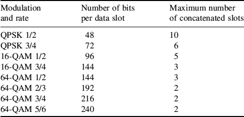
The number of input bits depends on the number of slots allocated by the MAC layer to the user for transmission. Table 8.32 shows the number of bits per data slot. Concatenation of a number of data slots is performed in order to make larger blocks for coding whenever possible, with the limitation of not exceeding the largest block defined in Table 8.32 for a given applied modulation and coding rate. A larger coding block improves the coding performance, but introduces higher decoding and computational complexity. To decode the above duo-binary CTC codes, MaxLogMap [54] has been adopted.

Figure 8.61 Convolutional turbo coding (CTC)
Table 8.32 Encoding slots concatenation for different rates in CTC
Interleaver
The interleaving operation ensures that adjacent coded bits are mapped onto nonadjacent OFDM subcarriers, and at the same time maps coded bits alternately on to less and more significant bits of the modulation constellation. The intention is to increase the robustness and avoid long runs of low-reliability bits. The operation is divided into two permutation steps. The first permutation equation is:
where i is the index after the first permutation of index k. k is the index of coded bits before first permutation. NCBPS is the encoded block size. The second permutation mapping index i to j is:
where s = max(NBPSC/2,1), with NBPSC being the number of bits per modulation symbol, for example two bits for QPSK. Note that the interleaver is not used for CTC.
Modulation
Permutation definition
Figure 8.62 shows the PRBS used to produce a random sequence, wk, that will be used for subcarrier randomization (after QAM mapping) and pilot modulation in the following. The polynomial for the PRBS generator will be X11 + X9 + 1. The initialization vector for the memory will follow the steps in [52].

Figure 8.62 PRBS for pilot modulation

Figure 8.63 QPSK, 16-QAM and 64-QAM constellations point
Data modulation
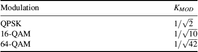
OFDM subcarriers are modulated using QPSK, 16-QAM, and 64-QAM constellations. The encoded and interleaved serial input data is divided into groups of NBPSC, i.e. 2, 4, or 6 bits, which will then be converted into a complex number, I + Q × j, representing either a QPSK, 16-QAM, or 64-QAM constellation point. The mappings for QPSK, 16-QAM and 64-QAM are shown in Figure 8.63. Finally, the resulting complex value is normalized by multiplying it by the normalization factor, KMOD, specified in Table 8.33. The constellation-mapped data is subsequently modulated on to the allocated data subcarriers, and each subcarrier is multiplied by the factor 2 × (1/2 − wk) according to the subcarrier index k. wk is derived using the method described above for permutation definition.
Pilot modulation
In the downlink, the pilot is transmitted with a boosting of 2.5 dB over the average nonboosted power of each data tone. The pilot subcarriers are modulated with sequence wk, defined earlier using the following equation:
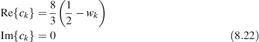
In the downlink, for PUSC, FUSC, AMC, and optional FUSC permutations, all pilots (of the segment, in the case of PUSC) will be modulated, whether or not all the subchannels are allocated in the DL-MAP. For AMC permutation in AAS zone, the BS is not required to modulate the pilots that belong to bins not allocated in the DL-MAP, or allocated as gaps (UIUC = 13).
Table 8.33 Modulation-dependent normalization factor
Subchannel Allocation
There are many types of subchannel allocation mechanism, grouped according to whether the transmission is uplink or downlink. For the downlink, the two main subchannel allocation methods are:
- Partial usage of subchannels (PUSC), where some of the subchannels are allocated to the transmitter.
- Full usage of subchannels (FUSC), where all of the subchannels are allocated to the transmitter.
FUSC employs full channel diversity by distributing data subcarriers to subchannels using a permutation mechanism designed to minimize interference between cells. It is somewhat similar to the idea of the classical frequency hopping technique. For PUSC, subchannels are divided and assigned to three segments, which can be allocated to sectors of the same cell. As with FUSC, a permutation mechanism is applied to allocate subcarriers to subchannels to harvest the interference averaging and fast-fading averaging effects. See [52] for details of the permutation mechanism.
Figure 8.64 shows the PUSC data frame, consisting of L subchannels across the time interval. Data can be transmitted over the subchannels depicted in the figure. In PUSC mode, a data slot is composed of one subchannel and two OFDMA symbols. The data region is the allocated area for user data transmission. The mapping of encoded data blocks onto the subchannels is depicted in Figure 8.64. The mapping follows the order in Figure 8.64 (vertical direction first, then proceed to the next two OFDMA time symbols).

Figure 8.64 Example of mapping encoded data blocks to subchannels in downlink PUSC mode [52]
Table 8.34 FUSC FFT parameters

IFFT/FFT
The IFFT block transforms the data from frequency to time domain, using inverse fast Fourier transforms at the transmitter while the FFT performs the reverse operation at the receiver. A highlight of the IEEE 802.16e standard is the idea of scalable OFDMA (SOFDMA), where the FFT size can be adjusted while fixing the subcarrier frequency spacing at a particular value. This is advantageous for supporting a wide range of bandwidths in order to flexibly address the need for various spectrum allocations, ranging from 1.25 Mhz to 20 MHz. The relevant FFT parameters for FUSC and PUSC schemes are shown in Tables 8.34 and 8.35, respectively.
8.4.3 Physical Layer Simulation Results and Analysis
This subsection describes the physical layer performance of the WIMAX system. The simulation parameters used are the WIMAX system parameters, which can be found in Table 8.36.
Other simulation parameters and assumptions are:
- ITU vehicular A and vehicular B channel models [55].
- A spectral mask of −5 dBc/Hz flat up to 10 kHz, and then reducing 20 dB/dec up to −120.
- Perfect channel knowledge.
Unless otherwise specified, the parameters above are assumed for the simulation results presented below.
8.4.3.1 Performance of WIMAX at Different Mobile Speeds
Figure 8.65 shows the performance of PUSC schemes for mobile speeds of 60 and 100 kmph in the ITU vehicular A channel. The FEC blocks sizes are indicated in the graph legends, in the range of 384–480 bits, depending on the modulation and coding setting. It can be seen that WIMAX is fairly robust to Doppler spread and the performance loss is minimal. Figure 8.66 further shows the BER performance at a mobile speed of 150 kmph. Comparing Figure 8.65 and Figure 8.66, the performance loss is still small, even when the 64-QAM 1/2 is used.
Table 8.35 PUSC FFT parameters
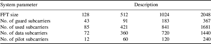
Table 8.36 System parameters of the WIMAX platform
| System parameter | Description |
| Duplexing | TDD |
| Multiple access | OFDMA |
| Subcarrier permutation | PUSC |
| Carrier frequency | 2.3 GHz |
| Channel bandwidth | 8.75 MHz |
| FFT | 1024 |
| Subcarrier spacing | 9.765 625 kHz |
| Symbol duration, TS | 102.4 μs |
| Cyclic prefix, TG | 12.8 μs |
| OFDM duration | 115.2 μs |
| TDD frame length | 5 ms |
| No. of symbols in a frame | 42 |
| DL/UL ratio | 27/15 |
| TTG/RTG | 121.2/40.4 μs |
Figure 8.67 further shows the result for ITU vehicular A BER and PER at 100 kmph using FEC blocks of 144 and 192 bits. When compared to Figure 8.65, there is a small performance loss. This is due to small block size being used; for the class of CTC codes, larger block sizes will have a better BER/PER performance. Nevertheless, the performance is still robust to Doppler spread, even at 100 kmph.
8.4.3.2 Performance of WIMAX with Different Channel Models
Figure 8.68 shows the BER and PER performance of ITU vehicular A and vehicular B channel at 60 kmph using FEC blocks of length 384–480 bits as defined in the graphs, depending on the modulation and coding setting. It can be seen that ITU vehicular B beyond 16-QAM 3/4 model has large performance degradation compared to the ITU vehicular A channel. This is due to the larger channel echo of the ITU vehicular B model than the guard interval of the defined system parameters in Table 8.36. While the defined system parameters target smaller cell size and low antenna, the figure shows that the system is still usable (and robust for modes below 16-QAM 1/2) at the larger cell size of the normal GSM/3G system. Note that this problem can be solved easily, by using a larger guard interval at the cost of reduced bit rate if a larger cell size is desired.
8.4.4 Error Pattern Files Generation
8.4.4.1 Data Flow over the Physical Layer
Figure 8.69 shows the physical layer time division duplex (TDD) frame of the WIMAX system. It contains downlink (DL) and uplink (UL) subframes with various regions for performing protocol functions and data transmissions. Basically, the DL data burst #x region is the allocated data region where a user can transmit data. As shown in Figure 8.69, a data burst generated by users is placed at the correct DL data burst, depending on the MAC scheduler allocation decision. The allocation decision is transmitted in the DL-MAP section of the DL subframe.

Figure 8.65 BER and PER performance of PUSC scheme at mobile speeds 60 kmph and 100 kmph

Figure 8.66 BER performance of PUSC scheme at mobile speed 150 km/h

Figure 8.67 BER and PER performance of the PUSC scheme at 100 kmph

Figure 8.68 BER and PER performance with ITU vehicular A and vehicular B channel

Figure 8.69 WIMAX physical layer TDD frame. Reproduced by Permission of ©2004, 2007 IEEE
8.4.4.2 Pregenerated Trace Format
(Portions reprinted, with permission, from C.H. Lewis, S.T. Worrall, A.M. Kondoz, “Hybrid WIMAX and DVB-H emulator for scalable multiple descriptions video coding testing”, International Symposium on Consumer Electronics (ISCE 2007), June 20–23, 2007, Dallas, Texas, USA. ©2007 IEEE.)
The developed WIMAX simulator has been compared to the literature for validation. It has been used to generate error pattern files. The format of the trace matches the TDD frame format. The system parameters are shown in Table 8.36. As PUSCs have been used, one data slot is equal to one subchannel and two time symbols. Thus, the DL subframe is a matrix of 30 × 13 data slots, excluding the preamble symbol.
In order to reduce data storage requirements, the error pattern is saved in the form of a data-slot error pattern instead of a bit error pattern. The data-slot error pattern is obtained by comparing all the data bits within an original data slot to the transmitted data slot. If there is any bit error within the data slot, it is declared as an error. Note that we have not specifically assumed any IP packet size or data burst size within a physical layer frame. Also, no MAC layer packet encapsulation procedures have been performed. This decision was made to allow flexibility on the choice of packet size and the data throughput during video transmission simulation. Data slots can be aggregated to different MAC frame sizes for different packet sizes, and different burst sizes for different data throughput. This also allows the study of efficient packetization schemes for video transmission. Maximum FEC code block size has been assumed for the trace generation. The maximum code block size is MCS mode-dependent, as defined in the IEEE 802.16e-2005 standard.
Table 8.37 Parameters used for trace generation
| Parameter | Values |
| Length of trace | 15 s |
| Permutation | PUSC |
| Channel coding | CTC |
| Terminal speed | 60, 120 kmph |
| Test environment | ITU vehicular A |
| MCS mode | QPSK 1/2, QPSK 3/4, 16-QAM 1/2, 16-QAM 3/4, 64-QAM 1/2 |
| SNR range | 0–30 dB, which will have 5–7 data points for each MCS mode |
For error pattern generation, the system parameters in Table 8.36 and the simulation parameters in Table 8.37 are used. Nevertheless, error patterns for other scenarios may be generated easily with the WIMAX simulator. For each MCS mode, 5–7 data points, each representing different SNR/BER levels, are generated. In the generated error pattern files, symbol 1 refers to a data slot error while symbol 0 means that there is no error.