
9.2 Link-level Quality Adaptation Techniques
(Portion reprinted, with permission, from C. Kodikara, S.T. Worrall, A.M. Kondoz, “Energy efficient video telephony over UMTS”, IEEE VTC-Spring 2004, 17–19 May 2004, Milan, Italy. ©2004 IEEE.)
Efficient transmission power utilization is an important design criterion in interference-limited cellular systems, such as UMTS networks. System capacity is limited by the total interference experienced within the cell coverage. Thus, the optimization of power consumption for an individual user can provide an increase in system capacity, as well as in the QoS experienced by the user.
Recently, several energy minimization techniques for wireless video applications have been proposed [17, 18]. All of these techniques are optimized to achieve a target video quality while minimizing the transmission power. In [18], joint error resilience and transmission power management at video frame level is proposed. However, as the video frame quality is variable in nature (even in an error-free environment), controlling the transmission power to achieve a target frame quality at the video frame level is inaccurate and would result in poor system performance. This problem can be solved by minimizing the total consumed power within a certain period, while achieving the optimal average video quality. The method proposed in [18] employs this concept for intra-refreshed video sequences, thus video performance is optimized for a fixed intra-refresh period. However, this method cannot be applied in conjunction with rate-controlled AIR techniques [19], which are commonly used to produce a smoother output bit rate for transmission over a fixed-bandwidth channel.
Another issue that should be considered in the design of transmit-power optimization schemes is the support of network compatibility and interoperability between different networks and platforms. Transmit power is normally allocated at the physical layer for a given TTI [20]. If the power-allocation algorithms are closely coupled with the video-compression formatting, it is impossible to implement such algorithms at the physical layer without modifying the entire protocol stack of the existing network.
The algorithm proposed in this section takes these issues into account in its design and implementation. In contrast to the method in [18], the proposed scheme can be applied equally to rate-controlled AIR video sequences and intra-refreshed sequences. The proposed method combines an unequal error-protection (UEP) technique and an unequal power-allocation (UPA) technique to obtain energy-efficient video transmission. UEP is performed with the use of two different radio bearers. At the start of every video frame, the transmission energy for different bearers is selected in such a way as to achieve the maximum expected video frame quality for an increment in the transmission power step.
9.2.1 Performance Modeling
The bitstream syntax of MPEG-4 uses a hierarchical structure. Each video frame is partitioned into smaller rectangular regions called macro blocks (MBs) (16 × 16 pixels in size). Each MB is coded either in inter-mode or intra-mode. Intra-mode MBs are transform coded directly without applying motion compensation, while inter-mode MBs use motion compensation. Consecutive MBs are grouped to form video packets (VPs). The MPEG-4-adopted VP format is shown in Figure 9.25. Synchronization markers are used to isolate VPs from one another. Following the concept of data partitioning, data within a VP is further divided into two main parts. The motion-related information for all the MBs contained in a given VP is placed in the motion part, and the relevant DCT data is placed in the texture part [21].
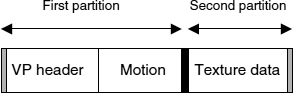
Figure 9.25 MPEG-4 VP format
Combining VPs in a video frame forms a video object plane (VOP). The most important information the decoder needs to know prior to the decoding of compressed video data is placed in the VOP header part. This includes the spatial dimensions of the video frame, the time stamps associated with the current frame, presentation information, and the mode in which the current frame is coded.
The video information is prioritized based on the MPEG-4 data partition techniques [22]. Information within the first partition is sent over a higher-priority channel. A lower-priority channel is used to transmit the data within the second partition. VP header information is added to the beginning of the second partition in order to guarantee accurate stream synchronization at the decoder. The VOP header is also repeated in the lower-priority channel at the start of the video frame. The video data formats in prioritized streams are shown in Figure 9.26.
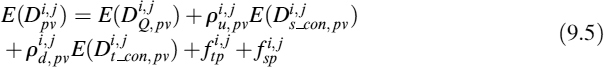
Video performance is modeled as a combination of quantization distortion, E(DQ,pv), and channel distortion. Channel distortion is divided into three parts, namely spatial concealment distortion, temporal concealment distortion, and distortion due to error propagation. The distortion method adopted in this paper is similar to the method proposed in [18]. However, the model in [18] is enhanced for the use of AIR and features improved error-propagation estimation.
If the video frame configuration information or VP headers are lost in the transmission, the decoding process is impossible and the data belonging to the VP has to be discarded at the decoder. However, the error-concealment tools implemented at the decoder replace the discarded data with error-concealed data from the neighboring packets. The distortion resulting from this process is called the spatial-concealment distortion, E(Ds_con,pv), as only spatial error concealment is involved in the process. On the other hand, if the configuration information, VP header information, and motion information is received correctly but the DCT information is corrupted, the decoder only discards the corrupted DCT data and replaces it with the corresponding concealed data from the previous frame. The distortion resulting from motion-compensated error concealment is called temporal-concealment distortion, E(Dt_con,pv).
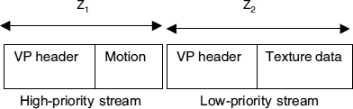
Figure 9.26 Video data format in prioritized streams
Errors can propagate in two ways; either in the temporal domain or in the spatial domain. Frame-to-frame error propagation through motion prediction and temporal concealment is called temporal-domain error propagation, ftp. The propagation of errors from neighboring VPs via spatial concealment is considered spatial-domain error propagation, fsp.
Taking the VP as the base unit, the expected frame quality can be written as:

where ![]() is the expected quality,
is the expected quality, ![]() is the expected distortion of the VP, and Ij is the total number of VPs in jth video frame. i and j represent the ith VP of the jth video frame. g is a constant defined by the dimension of the frame.
is the expected distortion of the VP, and Ij is the total number of VPs in jth video frame. i and j represent the ith VP of the jth video frame. g is a constant defined by the dimension of the frame. ![]() can be written as:
can be written as:
where ![]() denotes the probability of receiving an undecodable VP. This includes the corruption of VOP headers, VP headers, or motion data.
denotes the probability of receiving an undecodable VP. This includes the corruption of VOP headers, VP headers, or motion data. ![]() equals the probability of finding an error in the first partition. The probability of receiving a decodable VP, but with errors, where the DCT data is corrupted but other information is received correctly, is denoted by
equals the probability of finding an error in the first partition. The probability of receiving a decodable VP, but with errors, where the DCT data is corrupted but other information is received correctly, is denoted by ![]() . This equals the probability of finding an error in the second partition but not in the first partition. Both probability terms are functions of channel bit error rate, transmission bit energy, and total background noise power.
. This equals the probability of finding an error in the second partition but not in the first partition. Both probability terms are functions of channel bit error rate, transmission bit energy, and total background noise power.
9.2.2 Probability Calculation
Assuming that the probability of receiving a VOP header with errors in the high-priority channel is ![]() , the probability of receiving data within the first partition with errors is
, the probability of receiving data within the first partition with errors is ![]() , and the probability of finding an error in the second partition is χi,j. Then:
, and the probability of finding an error in the second partition is χi,j. Then:
If the probabilities of channel bit errors in channel 1 and channel 2 are denoted by ρb1 and ρb2 respectively, then it can be shown that:
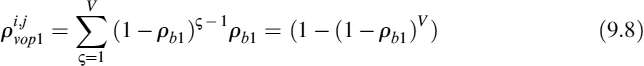
where V represents the VOP header size. Similarly:

Z1 and Z2 are as defined in Figure 9.26.
9.2.3 Distortion Modeling
The expected distortions, E(DQ,pv), E(Ds_con,pv) and E(Dt_con,pv), of the MBs are calculated as specified in [18]. The quantization distortion is computed by comparing the reconstructed MBs and the original MBs at the encoder. Concealment distortions are also computed in a similar manner. The transmitted video data belonging to each MB is corrupted using a noise generator located at the encoder. Corrupted data is replaced by the concealed data, and data belonging to the original and concealed MBs is compared. In the case of the spatial-concealment distortion calculation, only a spatial-concealment algorithm is used to generate the concealed data. On the other hand, a temporal-concealment algorithm alone is used to conceal the corrupted data for the temporal-concealment distortion calculation. The correct reception of neighboring VPs and reference video frames is assumed in the calculations.
9.2.4 Propagation Loss Modeling
Correlation between the corrupted VPs in the same frame and the distortion due to the MB mismatch in adjacent video frames is quantified by the spatial and temporal error propagation terms in (9.5).
The temporal propagation loss, ![]() , represents the propagation of corrupted information through predictive coding. An AIR algorithm, which uses a selected number of intra-coded MBs in a video frame, is used to prevent the error propagation. The temporal error propagation is calculated at MB level. Let
, represents the propagation of corrupted information through predictive coding. An AIR algorithm, which uses a selected number of intra-coded MBs in a video frame, is used to prevent the error propagation. The temporal error propagation is calculated at MB level. Let ![]() be the temporal error propagation of the kth MB in the jth frame.
be the temporal error propagation of the kth MB in the jth frame. ![]() depends on the coding mode used in the encoding of the MB.
depends on the coding mode used in the encoding of the MB. ![]() is calculated for inter-coded MBs as:
is calculated for inter-coded MBs as:

and for intra coded MBs as:
where ![]() and
and ![]() represent the spatial-concealment distortion and the temporal-concealment distortion of the MB, respectively. As before, i and j represent the ith VP in the jth video frame.
represent the spatial-concealment distortion and the temporal-concealment distortion of the MB, respectively. As before, i and j represent the ith VP in the jth video frame. ![]() is the spatial error propagation of the kth MB in the jth video frame.
is the spatial error propagation of the kth MB in the jth video frame. ![]() quantifies the fraction of distortion of the MB, which should be considered in the propagation loss calculation. The
quantifies the fraction of distortion of the MB, which should be considered in the propagation loss calculation. The ![]() is a function of effective channel bit error rate, ρbeff, and experimentally it is found to be approximated to:
is a function of effective channel bit error rate, ρbeff, and experimentally it is found to be approximated to:
where Fj is size of the jth frame, and X and Y are the total amount of data belonging in the first and the second partition, respectively. ![]() is computed as:
is computed as:

where Ω denotes the sets of MBs in the ith VP in the jth video frame. The spatial error propagation terms, ![]() and
and ![]() , depend on the number of corrupted VPs in a frame and only propagate through the spatial-concealment process. The
, depend on the number of corrupted VPs in a frame and only propagate through the spatial-concealment process. The ![]() and
and ![]() are modeled as:
are modeled as:
where ![]() and VPj represent the number of VPs and the average size of a VP in the jth frame, respectively.
and VPj represent the number of VPs and the average size of a VP in the jth frame, respectively.
9.2.5 Energy-optimized UEP Scheme
Let the user-requested video quality in terms of average frame PSNR be Qt arg et. The total channel interference and noise experienced is denoted by the noise power spectral density, No. The minimum required transmission energy for an information bit to satisfy the user quality requirement under a given channel condition is Ebmin. The expected video frame quality, E(Qfmin), is computed using (9.4). It is assumed that the data on both higher-priority and lower-priority channels is transmitted with equal bit energies, Ebmin. Point A in Figure 9.27 represents the estimated quality, E(Qfmin). Point E shows the expected quality, if the transmission energy on both channels is incremented by 1 dB.
The goal is to find the combination of transmission energies in the two channels which maximizes the current video frame quality for an increment in the transmission energy. The optimum energy allocation is to be found in the vicinity of point B. The possible combinations of transmission energy allocation in different priority channels are listed in Table 9.17. Even though it is valid to consider other transmission energy levels, the settings listed in Table 9.17 are more likely to provide optimum energy allocation. Moreover, this simplifies the searching procedure. The expected video frame qualities are computed for the energy settings listed in Table 9.17, and the corresponding points are shown in Figure 9.27.

Figure 9.27 Calculation of optimal transmission energy levels
Table 9.17 Possible combinations of transmission energy allocation

The transmission energy levels corresponding to the point that shows the highest gradient from point A provide the optimal energy levels for the transmission of the current video frame. This algorithm operates at the video-frame level to find the optimal operating point. It guarantees the end-user quality requirement and the optimal energy setting throughout the transmission.
9.2.6 Simulation Setup
Realization of the proposed energy-optimized UEP algorithm over a UMTS network is shown in Figure 9.28. At the encoder, each encoded video frame is separated into two streams based on MPEG-4 data partitioning. The separated streams are mapped on to two transport channels. The high-priority data is sent over the highly-protected channel, which is protected with a 1/3 rate convolutional code. A 1/2 rate convolutional code is used to protect the lower-priority channel. At the physical layer, the information on the transport channels is allocated the selected transmission bit energy and is multiplexed on to the same physical channel for the transmission over the air interface.
A UMTS physical link-layer simulator is developed. The simulator includes all the radio configurations, channel structures, channel codings/decodings, spreadings/despreadings, modulation parameters, and transmission modelings, and their corresponding data rates according to the UMTS specifications. The transmitted signal is subjected to a multipath fast-fading environment.
The multipath-induced inter symbol interference is implicit in the developed chip-level simulator. A detailed discussion of the channel simulations can be found in Chapter 8. Using the developed simulator, error characteristics of the transmission channel are simulated for a range of channel conditions and for different physical layer configurations.

Figure 9.28 Realization of proposed UEP/UPA over UMTS
The vehicular A propagation condition and downlink transmission are considered in the experiment discussed in this section. The mobile speed is set to 50 kmph. A spreading factor of 32 is used in the physical channel configuration. The experimentally-evaluated channel block error rates (BLERs) over the vehicular A environment are listed in Table 9.18.
Video sequences are encoded according to the MPEG-4 simple profile format. This includes the error-resilience tools such as video packetization, data partitioning, and reversible variable length code. The first video frame is intra-coded, while others use inter-coding. The TM5 rate control algorithm is used to achieve a smoother output bit rate, while an adaptive intra-refresh algorithm [19] is used to stop temporal error propagation. ITU test sequence Suzie is used as the source signal in the experiments. The QCIF (176 × 144 pixels) sequence is coded at 10 fps. Use of SF 32 in channel configuration permits 64 and 97 kbps information rates with 1/3 rate and 1/2 rate convolutional coding, respectively.
For the proposed algorithm, video coded at 88 kbps provides the appropriate source-channel coding ratio for the Suzie sequence.
Table 9.18 Channel BLER for vehicular A environment: CC, convolutional code

9.2.7 Performance Analysis
The accuracy of the developed distortion model is evaluated by comparing the estimated performance and the actual video performance over a simulated UMTS environment. Video performance is measured in terms of frame peak signal-to-noise ratio (PSNR), which is the standard objective quality measurement. Each experiment is repeated 20 times in order to average the effect of bursty channel errors on the performance. The average frame PSNR is obtained by averaging over 6000 frames, and the results are shown in Figure 9.29. The experimentally-evaluated channel BLER (see Table 9.18) is used in the theoretical performance calculation. As can be seen in Figure 9.29, the theoretical PSNR values closely match the actual PSNR values for a wide range of channel conditions.
Experiments were conducted for a range of channel conditions for both a data partition-based UEP (DP-based UEP) scheme and the proposed power-optimized UEP scheme. Results are shown in terms of average Eb/No vs. average frame PSNR in Figure 9.30. The performances of 1/2 rate and 1/3 rate convolutional code without application of UEP are also shown. The figure clearly demonstrates that more efficient energy utilization is achieved with the proposed method than with the traditional DP-based UEP scheme or the non-UEP schemes. Video performances are limited by the quantization distortion with good channel conditions. In such situations, increasing the transmit power will not further increase the performance. This effect is well captured by the proposed algorithm, and the highest allocated transmit Eb/No is limited to 11.2 dB. For the allocation of higher transmission energies, the proposed algorithm shows close performance to that of a DP-based UEP scheme. However, the proposed algorithm considerably outperforms DP-based UEP schemes at lower transmit energy. For example, for transmission of the Suzie sequence, the achieved average frame PSNR with a DP-based UEP scheme is 18 dB for 6 dB energy allocation. The proposed power-optimized UEP scheme results in average frame PSNR of 24 dB for the same transmit bit energy allocation.

Figure 9.29 Validation of model performance for DP-based UEP scheme

Figure 9.30 Performance of the proposed algorithm for transmission of Suzie
9.2.8 Conclusion
An energy-efficient network-compatible performance-enhancement method is proposed for video communication over direct-sequence CDMA cellular networks. Prioritized video information is transmitted over two different transport channels with different error-protection capabilities. Transmit energy for each bearer is selected to maximize the expected frame quality for an increment in transmit energy. The experiment carried out over the simulated UMTS system shows significant performance improvement with the proposed algorithm over the traditional DP-based UEP schemes and non-UEP schemes.