
10.3 Implementation of a QoS-optimized Inter-networked Emulator
This section describes the implementation of the proposed QoS architecture for EDGE-UMTS systems. The implementation follows a detailed description of each element of the QoS architecture, which is explained in Section 10.2. The generic QoS architecture described in Section 10.2 is applicable to any heterogeneous network system. However, the EDGE-UMTS system has been used as a case study due to its popularity in 3G wireless communication systems.
Figure 10.3 shows the role of the QoS architecture in a practical operating environment, i.e. EDGE-UMTS. The system consists of five components: a transmitting mobile terminal, EDGE emulator, QoS mapping emulator, UMTS emulator, and receiving mobile terminal, as shown in Figure 10.4. The terminal emulator emulates the mobile terminal and is capable of transmitting and receiving multimedia data. An MPEG-4 data transmitter and decoder are integrated into the terminal emulator. The received data is decoded in real time and is displayed on the terminal emulator.

Figure 10.2 The proposed QoS architecture. Reproduced by Permission of ©2005, 2007 IEEE

Figure 10.3 EDGE-UMTS parameter mapping emulator. Reproduced by Permission of ©2005 IEEE
The EDGE emulator consists of two parts: the GERAN data flow model and the EGPRS physical link layer model. The physical link layer model simulates the physical layer characteristics of the channel between the EDGE mobile terminal and a base station. The model includes forward error correction, modulation, and transmission over fading channels, equalization, and reception and detection of correctable and uncorrectable errors. The transmitted signal is subjected to a multipath fast-fading environment. The simulator model was built using the COSSAP stream simulation environment and closely follows the standard specification [13].
The EGPRS data flow simulator is implemented to carry out detailed examinations of the effects of channel errors upon applications. The model was implemented in C++. The layers implemented include RTP/UDP/IP transport layers and GPRS SNDC, LLC, and RLC/MAC layer protocols. It must be emphasized that only the data flow properties of the protocols have been implemented in this model. This means that only the resulting effects on header sizes, packet- and stream-segmentation procedures, and flow-control have been implemented.
Similar to the EDGE emulator, a UMTS emulator, which consists of the UTRAN data flow model and WCDMA physical layer, is implemented. The WCDMA physical layer model was developed in a generic manner that enables easy configuration of UTRAN link-level parameters such as channel structures, channel coding/decoding, spreading/de-spreading, modulation, transmission modeling, and propagation environments, and their corresponding data rates according to the 3GPP specifications [14]. The multipath-induced inter-symbol interference is implicit in the developed chip-level simulator. By adjusting the model parameters, the bit error and block error characteristics can be determined for a range of signal-to-noise ratios (or carrier-to-interference ratios) and for different physical layer configurations. A UMTS radio interface protocol model, which represents the data flow across the UTRAN protocol layers, is implemented in Visual C++. It is integrated with the physical link layer model to emulate the actual radio interface experienced by users. This allows for interactive testing of the effects of different parameter settings of the UTRAN upon the received multimedia quality. Also, it provides information on channel utilization and system complexity for the given connection.

Figure 10.4 QoS mapping emulation system architecture
The QoS mapping emulator written in Visual C++ 6.0 is a relay program between the EDGE emulator and the UMTS emulator. To some extent, the QoS mapping emulator can be regarded as the combination of the EGPRS emulator and UMTS emulator. It receives the data sent by the EDGE emulator, changes it to UMTS format, and sends it the UMTS emulator, and vice versa. If necessary, a trans-coding function can be added to the parameter-mapping program.
In the following, the structure of the QoS mapping emulation system and the function of each component of the emulation system are presented.
10.3.1 Emulation System Physical Link Layer Simulation
Error pattern files produced by the EGPRS physical link layer simulator and UMTS physical link layer simulator are used to simulate the real mobile communication environment. The EGPRS and UMTS physical link layer simulators have been implemented using the COSSAD and Signal Processing WorkSystem (SPW) software simulation tools, respectively. The physical link layer parameters used in the simulators are listed in Tables 10.1 and 10.2. A detailed description of EGPRS and UMTS physical link layer simulators is given in Chapter 8. Using these physical link layer simulators, a set of error pattern files is produced for different radio bearer configurations. These error pattern files are used to emulate the effect of physical condition on transmitted data.
Table 10.1 EGPRS simulator parameters
| Parameter | Settings |
| Channel Coding Scheme | GPRS CS-1 ~ 4, HSCSD TCH/F9.6, TCH/F14.4, EGPRS PDTCH |
| Supported | MCS-1 ~ 7 |
| Interleaving | Block rectangular over four frames for GPRS; as specified in GSM 05.01 for EGPRS |
| Training Sequence Codes | Eight codes available |
| Modulation | GMSK, 8-PSK |
| Interference Characteristics | User-definable static C/I ratio for single co-channel interferer. May also be disabled. No frequency offset |
| Fading Characteristics | Rayleigh fading for each path (Rice for one component of RA). Fading varies during one burst |
| Multipath Characteristics | TU, RA, HT propagation environments supported, as in GSM 05.05 |
| Transmission Capabilities | User-definable. Can simulate no frequency hopping and ideal frequency hopping (no correlation between successive bursts) |
| Mobile Terminal Velocity | User-definable. Static -> 250kmph (for 900 MHz) |
| Carrier Frequency | User definable to 900 MHz or 1800 MHz |
| Antenna Characteristics | 0 dB gain for both transmitter and receiver. No antenna diversity |
| Signal-to-Noise Characteristics | AWGN source at receiver. User-definable Eb/N0 ratio |
| Burst Recovery | Synchronization based on the cross-correlation properties of the training sequence |
| Equalizer | 16-state soft-output MLSE equalizer for GMSK; 16-state decision-feedback MLSE equalizer for 8-PSK |
| Channel Decoding | Soft-decision Viterbi convolutional decoder. Fire correction and detection for CS-2–4 and MCS-1–9 |
| Performance Measures | Bit error patterns and block error patterns |
| Simulation Length | User-definable. Most experiments run for 15 000 blocks/timeslot |
Table 10.2 UMTS simulator parameters
| Parameters | Settings |
| CRC Attachment | 24, 16, 12, 8, or 0 |
| Channel Coding Scheme | No coding, 1/2 rate convolutional coding, 1/3 rateconvolutional coding, |
| Supported | 1/3 rate turbo coding |
| Interleaving | 1st interleaving: block interleaver with inter-frame permutation
2nd interleaving: block interleaver with inter-columns permutation Permutation patterns are specified in [15] |
| Rate Matching | Simplified version of the algorithms (for convolutional rate matching and turbo rate matching) as specified in [15]. Rate matching ratio (repeat or puncturing ratio) is user-definable |
| TrCH Multiplexing | Experiments were conducted for two transport channels. Can be extended to a higher number of transport channels |
| Transport Format | TFCI-based detection |
| Detection | |
| Spreading Factor | 512, 256, 128, 64, 32, 16, 8, 4 |
| Transmission Time | 10 ms, 20 ms, 40 ms, 80 ms |
| Interval | |
| Pilot Bit Patterns | As specified in [14] |
| Interference/Noise Characteristics | User-defined values are converted to the variance of AWGN source at receiver |
| Fading Characteristics | Rayleigh fading mobile channel impulse response is updated 100 times for every coherence time interval |
| Multipath Characteristics | Vehicular, pedestrian |
| Mobile Terminal Velocity | User-definable. Constant for the simulation run |
| Chip Rate | 3.84 Mcps |
| Carrier Frequency | 2000 MHz |
| Antenna Characteristics | 0 dB gain for both transmitter and receiver antenna |
| Receiver Characteristics | Rake receiver with maximum ratio combining, equal gain combining or selective combining. The number of rake fingers is user-definable |
| Transmission Diversity | Space-time block coding-based transmit antenna |
| Characteristic | Diversity (STTD) as defined in [14]
Closed-loop fast power control [16] |
| Channel Decoding | Soft-decision Viterbi convolutional decoder
Standard LogMap turbo decoder Number of turbo iterations is user-definable. |
| Performance Measures | Bit error patterns and block error patterns |
| Simulation Length | 3000–6000 radio frames, equivalent to 30–60 s duration |
The EGPRS emulator, which is described in Chapter 8, is used to simulate data transmission in real EGPRS networks. However, a few new features are added to the implementation presented in Chapter 8. These are:
- New channel schemes (MCS-1–9) simulation in RLC layer.
- Retransmission.
- Connection with QoS mapping emulator or another EGPRS emulator.
- Header corruption setting in each layer.
- Timeslots setting.
The UMTS emulator, which was designed to simulate data transmission in real UMTS networks, was also improved to support RLC AM (retransmission).
10.3.2 Emulation System Transmitter/Receiver Unit
MPEG-4 File Transmitter (Figure 10.5) is used to transmit the encoded MPEG-4 video file (*.cmp) to other emulators or to MPEG-4 Decoder. MPEG-4 Decoder (Figure 10.6) is designed to decode the received MPEG-4 video packets and display them on the screen. Writing received packets to file (*.yuv) is supported.
MPEG-4 Terminal combines the functions of MPEG-4 File Transmitter and MPEG-4 Decoder (Figure 10.7). This new program has a mobile handset shape. Users can press the keys to decode received MPEG-4 data or transmit MPEG-4 data to other emulators. Pressing the power key closes the program. Pressing the dial/answer key begins receipt of MPEG-4 data, while pressing the hang-up key stops receipt of MPEG-4 data. The message key, which is above the dial/answer key, is in control of sending MPEG-4 data to other emulators. Pressing the right mouse button will open a dialog to set the transmission and receiving parameters. The program can be run on Windows 2000 or XP.
10.3.3 QoS Mapping Architecture
The QoS mapping emulator, written in Visual C++ 6.0, is a relay program between the EGRPS emulator and UMTS emulator. To some extent, the QoS mapping emulator can be regarded as the combination of the EGPRS emulator and UMTS emulator. It receives the encapsulated data sent by the EGPRS emulator, decapsulates it to MPEG-4 data, then encapsulates the MPEG-4 data in UMTS format and sends it to the UMTS emulator, and vice versa.

Figure 10.5 MPEG-4 File Transmitter interface

Figure 10.6 MPEG-4 Decoder interface
If necessary, transcoding function can be added to the program. To simulate the EGPRS and UMTS protocols precisely is impossible and unnecessary. Some simplifications and modifications of the protocol are considered in the implementation. In Figure 10.8, the working process of the QoS mapping emulator is shown.
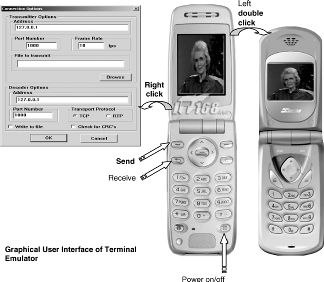
Figure 10.7 MPEG-4 Terminal

Figure 10.8 Flow diagram of QoS mapping emulator
10.3.3.1 EGPRS Module
The EGPRS module of the QoS mapping emulator supports two modes:
- Emulator (EMU) mode: The QoS mapping emulator connects the EGPRS emulator and UMTS emulator. In the UMTS-to-EGPRS direction, the EGPRS module will encapsulate MPEG-4 data decapsulated from the UMTS module, and send it to the EGPRS emulator, while in the EGPRS-to-UMTS direction, it will decapsulate the data received from the EGPRS emulator and transfer it to the UMTS module.
- Mobile Station (MS) mode: The QoS mapping emulator only connects the MPEG-4 file transmitter and MPEG-4 decoder. The EGPRS simulation (encapsulation and decapsulation) will all be done in this module. This mode is only for where no separate EGPRS emulator or UMTS emulator is present. If an EGPRS emulator and a UMTS emulator are available, the MS mode is not recommended, because it cannot provide a vivid display and flexible parameter setting.
10.3.3.2 EGPRS Data Flow Model
As Figure 10.8 shows, the basic concept of the simulation is to encapsulate the MPEG-4 data from the transport layer to the physical link layer, or decapsulate the data received from another emulator in the reverse direction. The following subsections will describe the encapsulation process.
Transport Layer (RTP/UDP/IP)
The frames of the encoded MPEG-4 video will be segmented into packets of the maximum size of 1520 bytes, and a 40 byte RTP/UDP/IP header will be inserted into the packet data. The content of the header is not important. This project focuses on the extent to which header corruption may affect QoS. In the program, 40 continuous “0”s are inserted into the front of the packet data as the header flag. If the receiver detects that the RTP/UDP/IP header does not contain 40 continuous “0”s, it will set the whole packet with “0”s, which adds additional errors to the transmitted stream.
SNDCP Layer
The main role of the SNDCP layer is to control header compression for IP packet data. QoS for any real-time traffic that uses small IP packets (e.g. speech) may require compression. For example, voice-over-IP (VoIP) is often carried in RTP/UDP/IP where the uncompressed header has a size of 40 bytes, but the speech typically only occupies 20–24 bytes (depending on the voice codec). Compression can cut the header to only four bytes most of the time. Given its complexity, the emulator does not have the header compression function. In most cases, video packets will be much bigger than the header size. Hence, the header compression function may not have much effect on the emulation results. Header compression is not always used in real environments.
SNDCP has two different SN-PDU formats:
- SN-DATA PDU, for acknowledged data transfer. Its header occupies three bytes.
- SN-UNITDATA PDU, for unacknowledged data transfer. Its header occupies four bytes [17].
For the same reason mentioned above, the emulator uses SN-UNITDATA PDU format. Header content is still not important. In the program, “1234” is set as the SNDCP header flag. If the receiver detects that the SNDCP header is not “1234”, the whole packet will be set to “0”s, which adds additional errors to the transmitted stream.

Figure 10.9 EGPRS LLC frame format [18]
LLC Layer
Each LLC frame consists of a header, trailer, and information field. The frame header consists of the address field and control field, as shown in Figure 10.9. The address field occupies one octet, while the control field typically consists of between one and three octets [18]. In the program, the LLC header is set to occupy three octets. The content of the header is not important, and is not the main feature that this project should consider.
The trailer is the frame check sequence (FCS) field, which consists of a 24 bit cyclic redundancy check (CRC) code. The emulator also takes its value as the FCS size.
The minimum value of the maximum number of octets in an information field (N201) will be 140 octets, and the maximum value will be 1520 octets. To simplify the complexity, the emulator let the N201 equal 1520 octets. If packet data is greater than 1520 octets, it will be segmented.
RLC/MAC Layer
The simulation in this layer is important, since GPRS and EGPRS have different structures in the layer. Although channel coding is not implemented in this layer, its schemes can affect RLC/MAC block structure.
For GPRS
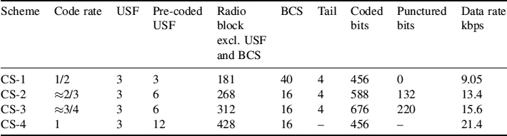
The RLC/MAC block for GPRS data transfer consists of a MAC header (fixed length) and an RLC data block, as shown in Figure 10.10. The RLC data block consists of an RLC header (variable length), an RLC data unit, and spare bits GPRS uses CS-1 to CS4 coding schemes (Table 10.3).

Figure 10.10 RLC/MAC block structure for data transfer for GPRS [19]
Table 10.3 Parameters for GPRS channel coding schemes with one timeslot [20]
The emulator only focuses on the header size and payload size. The other parameters of the block can be ignored. In the program, three continuous “12”s are set as the RLC/MAC header flag. If the receiver cannot detect the flag, the corresponding RLC block will be dropped.
For EGPRS
The RLC/MAC block for EGPRS data transfer consists of a combined RLC/MAC header and one or two RLC data blocks, as shown in Figure 10.11. Each RLC data block contains octets from one or more upper-layer protocol data unit (PDU).
Depending on the modulation and coding scheme, one or two RLC data blocks are contained in one RLC/MAC block. For MCS-1–6 there is one RLC data block, whereas for MCS-7–9 there are two, as shown in Table 10.5. In each transfer direction, uplink and downlink, three different header types are defined (Table 10.4):
- Header type 1 is used with MCS-7–9.
- Header type 2 is used with MCS-5 and 6.
- Header type 3 is used with MCS-1–4 [19].
Different header types have different header sizes in downlink and uplink directions.
As mentioned before, the emulator only considers the header size and payload size; other parameters can be ignored.
Retransmission
EGPRS supports retransmission with resegmentation, while GPRS only supports retransmission with the same coding scheme. Tables 10.6 and 10.7 show the choice of MCS for retransmissions.
The emulator supports the retransmission function, but has undergone some modification to simplify the implementation. The transmitter will push each packet into a queue. After an encapsulated packet is sent out, it will wait for the acknowledgement. If the receiver (EGPRS emulator) detects that the received packet cannot be decapsulated correctly, it will send a NACK for retransmission. If the process is correct, it will also send an ACK to signal that the next packet can be sent. The transmitter will pop the corresponding packet from the queue. It should be noted that the 3GPP standard requires layer 2 retransmission at the RLC PDU level; however, retransmission is actually performed at the RLC SDU level in the developed emulator. This is to enable minimization of the emulator complexity, without significantly affecting the overall emulator performance.
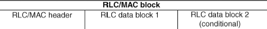
Figure 10.11 RLC/MAC block structure for data transfer for EGPRS [19]
Table 10.4 RLC/MAC header sizes in EGPRS

Table 10.5 Coding parameters for EGPRS coding schemes with one timeslot [20]

NOTE: italics indicate padding.
Timeslots
RLC/MAC blocks will be allocated with timeslots. Any number of timeslots from one to eight can be allocated (one block with one timeslot). The emulator allows the user to change the number of timeslots allocated to each connection.
10.3.3.3 UMTS Module
RLC/MAC blocks will be forwarded to the physical link layer. To simulate the transmission corruption in this layer, error pattern files are introduced. The emulator will read the file at a random position and make the exclusive OR operation between the encapsulated information data and the bits of the error pattern file. After the corruption simulation, the data steam will be transferred to the EGPRS emulator. The emulator offers header corruption configuration. A user can tick a check box to see the effect with or without header corruption on each layer. If the header corruption setting of a layer is ticked off then the header flag of that layer will be reset in the data for transmission. The reset operation is carried out behind the corruption simulation process. Decapsulation is similar to encapsulation, but in the reverse direction.
Table 10.6 Choice of MCS for retransmissions with resegmentation [19]

NOTE: MCS to use for retransmissions when resegmentation (RESEGMENT bit set to ‘1’) is carried out (specified as a function of the scheme used for the transmission).
Table 10.7 Choice of MCS for retransmissions without resegmentation [19]

NOTE: MCS to use for retransmission when resegmentation is not (RESEGMENT bit set to ‘0’) is not allowed (specified as a function of the scheme used for the initial transmission).
The UMTS module of the QoS mapping emulator also supports two modes:
- EMU mode: In UMTS-to-EGPRS direction, the module will decapsulate MPEG-4 data received from the UMTS emulator and send it to the EGPRS module, while in the EGPRS-to-UMTS direction it will encapsulate the data forwarded from the EGPRS module and transfer it to the UMTS emulator.
- MS mode: The UMTS simulation (encapsulation and decapsulation) will all be done in this module. It should be noted that the AM mode of the RLC layer is temporally unsupported in this mode. This mode is not recommended when the EGPRS emulator and UMTS emulator are available.
10.3.3.4 UMTS Data Flow Model
Figure 10.12 shows the UMTS module data flow. Encapsulation is just the reverse process of decapsulation. In MS mode, the emulator will implement both the encapsulation and the decapsulation process. In EMU modes, only one of these processes is implemented.
Transport Layer
Two connection types are supported in this layer:
- Packet-switched (PS): A 40 byte header will be inserted into the encoded video frame. In the program, 40 continuous “0”s are set as the flag. Segmentation will be implemented when the encoded video frame size is greater than 1520 bytes.
- Circuit-switched (CS): No header will be added to the video frame.
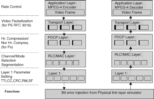
Figure 10.12 UMTS module data flow
PDCP Layer
The main role of the PDCP layer is similar to that of the SNDCP layer in GPRS, which is control of header compression for IP packet data. In the emulator, PDCP-no-header PDU is adopted. The PDCP-no-header PDU does not introduce any overhead to the PDCP SDU [21].
RLC/MAC Layer
The RLC layer will segment the data forwarded from higher layers into RLC blocks. Transport block (TB) size determines the size of the RLC blocks.
There are three types of RLC PDU for data transmission:
- Transparent Mode Data (TMD) PDU: The TMD PDU is used to transfer user data when RLC is operating in transparent mode. Hence, no overhead is added to the SDU by RLC.
- Unacknowledged Mode Data (UMD) PDU: The UMD PDU is used to transfer user data when RLC is operating in unacknowledged mode. The UMD PDN header occupies the first octet of the data stream.
- Acknowledged Mode Data (AMD) PDU: The AMD PDU is used to transfer user data, piggybacked status information, and the polling bit when RLC is operating in acknowledged mode. The AMD PDU header occupies the first two octets of the data stream.
The emulator supports the acknowledged mode. But some simplifications and modifications have been made to reduce the implementation complexity. If the emulator works in the acknowledged mode, the transmission part will push every frame into a queue. When the receiver detects there is header corruption in the received RLC blocks, it will order the transmitter to retransmit the whole frame, which is stored in the transmitter's queue. Retransmissions of the RLC blocks have been tried, but the results cannot be accepted since the whole emulation system is slowed down. Further proper optimization may solve the problem.
MAC entities can handle either the dedicated transport channel or the high-speed downlink shared channel. If channel multiplexing is performed at the MAC layer, a 4 bit MAC header is added to each RLC block [22].
Layer 1 (Physical Layer)
Layer 1 will attach a selected CRC to the RLC/MAC blocks. TTI blocks are formed by combining RLC/MAC blocks according to the specified TTI length, before transmitting over the air interface. The channel coding scheme, spreading factor, and rate-matching ratio, which can be specified by the user, determine the number of PDUs to be encapsulated within the TTI blocks.
Error pattern files are introduced in this layer to emulate the possible corruption in the real environment. The emulator will read the error pattern file from a random position and make the exclusive OR operation between the encapsulated information data and bits of the error pattern file.
10.3.4 General User Interface
The graphical user interface is designed in the Visual C++ environment. This provides a platform for user interaction as well as user QoE evaluation. The user is allowed to change most of the radio network parameters and visualize the effect of these parameters on multimedia quality. Figure 10.13 shows a snapshot of the developed graphical user interface.
In the main interface (Figure 10.14), the user can set the radio bearer parameters of the EGPRS module and UMTS module. The transmission status and performance of each module are also displayed in the main interface. In addition, the user is allowed to change the number of timeslots allocated to the current connection and the total number of users in the system while media is being delivered. This facilitates the visualization of received video quality instantaneously.

Figure 10.13 Graphical user interface of QoS architecture
Figure 10.15 shows the QoS parameter configuration dialog. The user can select the desired QoS parameters, such as type of service, traffic class, data rate, residual bit error rate, and transfer delay. The page will also show operator control parameters, connection type, PDCP connection type, and the number of multiplexed transport channels. Not all parameters are available; some are designed for future use.
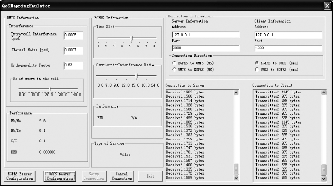
Figure 10.14 Main interface of QoS mapping emulator

Figure 10.15 QoS parameters configuration interface
The physical/radio channel parameter dialog (Figure 10.16) displays the appropriate spreading factor calculated based on the requested QoS parameters. In this dialog, the user can select the radio channel-related settings (carrier frequency, channel environment, mobile speed) and receiver characteristics (number of rake fingers, rake combining, diversity techniques, and power control). The transport channel (data channel) parameter dialog (Figure 10.17) allows users to define logical channel type, RLC mode, MAC channel type, MAC multiplexing, layer 1 parameters, TTI, channel coding scheme, and CRC. TB size and rate matching ratio, calculated from the other input parameter values, are also displayed. The user can change the settings of the channel coding scheme, header corruption, and retransmission in the EGPRS property dialog (Figure 10.18). In general the parameters are set before the emulator runs, but adaptive parameter configuration in runtime is supported.

Figure 10.16 Physical/radio channel parameters configuration interface

Figure 10.17 Transport channel (data channel) parameter configuration interface

Figure 10.18 EGPRS parameter configuration interface. Reproduced by Permission of ©2005 IEEE