
Flowchart Shapes Overview
Business processes are drawn as a flowchart. All business processes start with the Begin shape. There is exactly one Begin shape in an XLANG schedule drawing. You can add other shapes to the drawing and connect them to construct a flowchart rooted at the Begin shape. The connections between shapes denote a flow of control along that path. Each flow of control eventually terminates in either the End shape or the Abort shape. The End shape completes the process flow for that path. The Abort shape terminates a transaction and causes actions related to transaction failure to occur. This behavior is described in the “Transactions” section later in the chapter. Now, let's look at the shapes used to describe the process flow between these begin and end shapes.
The Action shape denotes a step in the process flow. You use an Action shape if you want to do something at this point in the process flow, and therefore you will bind this action to some implementation code later on. Chapter 10 covers this binding procedure in depth.
If you had no other shapes, you would be limited to defining just simple, sequential, business process flows. However, this is not the case. The Decision shape can be used to change the flow of control by using rules to test for data or status values. The While shape can be used to iterate a process flow. Many times business processes are not sequential; instead, parts of a process can occur in parallel. To exploit parallelism, you can use the Fork and Join shapes. Finally, you have the Transaction shape that is used to express the fact that the enclosed set of actions and process flows must occur as a transacted unit. A range of options are available to you to control the semantics of such a transaction.
To summarize, Table 9.1 shows the flowchart shapes available to you and describes each shape. Note that the names Begin, End, Decision, While, Fork, Join, and Abort are reserved names; you cannot use these names to name your shape instances.
| Shape | Description |
|---|---|
| Begin—Starting point for the business process | |
| End—Termination point for any path in the business process | |
| Decision—Alternate pathways taken based on the value of an evaluated rule | |
| While—Repeated execution of a process flow pathway | |
| Fork—Concurrent execution of pathways | |
| Join—Rendezvous point for concurrent execution pathways | |
| Transaction—Enclosed actions treated as within a transaction boundary | |
| Abort—Force failure of an enclosing transaction | |
| Action—A processing step within a business process |
At this point, it would be beneficial to review some elements of the Data page before diving into the details for the flowchart shapes. The Data page itself is covered in depth in Chapter 10. Figure 9.3 shows the data page from the Buyer1.skv schedule introduced in Figure 9.2 earlier.
Figure 9.3. A sample Data page.
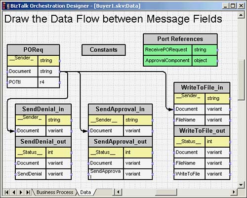
Figure 9.3 shows messages in the Buyer1.skv schedule. Note the message names, message fields, and arrows used to specify data flow between fields.
The Data page displays the messages used in the process flow. A message is associated with an action on the Business Process page. The messages are shown with the data fields that they contain. These fields have an associated data type. For incoming messages, the value of the field is populated by the sender; for outgoing messages, the value of the field must be populated by the XLANG schedule. Some message fields are provided as a standard part of BizTalk Orchestration Services; these fields are called system fields. The data values in any field can be used to construct rule expressions described in the “Rules” section later in the chapter. Special, built-in messages also are available on the data page, called constants and port references. With this rudimentary introduction to the Data page, you can now understand the rules in an XLANG schedule.