C H A P T E R 5
Control Flow Basics
You cannot always control what goes on outside. But you can always control what goes on inside.
—Self-help advocate Wayne Dyer
The previous chapter introduced you to SQL Server 11’s connection managers. The purpose of this chapter is to introduce some of the basic control flow items that will enable you to utilize those connection managers. The control flow has its own designer page in the Designer window in Visual Studio. In this chapter, we detail the control flow tasks that you are most likely to use on a daily basis. Chapter 6 covers the less frequently used executables. The control flow defines the operations that a package performs, and the order and conditions required to execute them.
What Is a Control Flow?
The control flow is the backbone of any SQL Server Integration Services 11 package. It consists of executables, containers, and precedence constraints. Executables are the most versatile component of an SSIS package. They include such tasks as the Execute SQL task, Data Flow task, and Script task. These tasks can be used to start stored procedures, extract and load data, and change the states of variables. Containers are used to logically organize the tasks. The containers can be used to simply organize or to loop through the tasks. Precedence constraints determine the execution path or flow. They allow you to determine the order of the tasks’ execution. By not defining certain constraints, you can take advantage of concurrent task execution.
The control flow designer pane has a zoom tool that allows you to zoom in and out to see all the components. The SSIS Toolbox also changes to allow you to access only the context-specific items. The data flow components are not available in the control flow. When adding items to the control flow, you have two choices: you can either click and drag the item from the SSIS Toolbox onto the control flow, or you can double-click the item.
Depending on the item being added to the control flow, we recommend having the referencing objects in place before adding the item. For example, if you are adding an Execute SQL task, create a connection manager to the database, or if you are adding a loop container, create the variable that it may depend on first. Having the requirements of the process are essential in developing SSIS packages efficiently. Creating objects in the reverse order on the fly is as close as you can get to spaghetti code in SSIS. With the autoformatting options, convoluted precedence constraint flows can be minimized.
![]() NOTE: Because the control flow represents the package itself, the package properties are available by right-clicking on the control flow designer background. Each of the components within the control flow has its own set of properties distinct to itself, but the control flow’s properties are the package properties.
NOTE: Because the control flow represents the package itself, the package properties are available by right-clicking on the control flow designer background. Each of the components within the control flow has its own set of properties distinct to itself, but the control flow’s properties are the package properties.
SSIS Toolbox for Control Flow
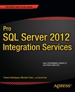
The components for the control flow are contained within a collapsible/closable window in Visual Studio known as the SSIS Toolbox. This window gives you access to all the components available for the control flow. We should note that this window is context specific, so when you are using the different designer windows, it will show tools available for that designer. The different components are categorized in the groups shown in Figure 5-1.
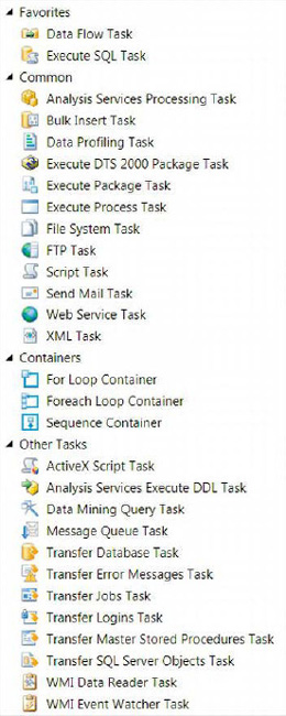
Figure 5-1. Control flow SSIS Toolbox
These groupings, which allow you to organize your SSIS Toolbox in a way that will give you quick access to the components you use most frequently, are as follows:
Favorites represents the most frequently used components. This category organizes the components in an easy-to-find place at the top of the SSIS Toolbox. By default, the Data Flow task and the Execute SQL task are placed in this category.
Common organizes the commonly used components utilized in SSIS development. These components are useful for the non-ETL aspects of the ETL process. These components allow you to manipulate the source or destination of the data so that it can be extracted or loaded more easily.
Containers groups together the different task containers. These containers execute tasks as defined by precedence constraints.
Other Tasks holds the tasks that are not usually used. These tasks are related more to database administration and nonfunctional requirements than they are to ETL.
Your customizations to the SSIS Toolbox will carry forward for all projects and can be modified at any time. If you want to revert to the default setup, you can right-click and select the Restore Toolbox Defaults option. One of the key features that makes the SSIS Toolbox effective in development is the unique icon for each of the components. The icons represent the purpose of each task in a meaningful way. These icons also appear on the component itself after it has been placed in the control flow.
![]() NOTE: In prior versions of BIDS, the name of the window pane was Toolbox. With SQL Server Integration Services 11, the name has changed to SSIS Toolbox. If you create your own custom component for the control flow, you have to add it to the assembly folder of the machine as well as the appropriate components folder for the SQL Server Installation. Chapter 21 covers custom components further.
NOTE: In prior versions of BIDS, the name of the window pane was Toolbox. With SQL Server Integration Services 11, the name has changed to SSIS Toolbox. If you create your own custom component for the control flow, you have to add it to the assembly folder of the machine as well as the appropriate components folder for the SQL Server Installation. Chapter 21 covers custom components further.
The SSIS Toolbox contains many components that assist with ETL requirements. In this book, we are dividing the list into basic and advanced components. This chapter covers the basic tasks that will likely be part of most solutions you design. Some of these tasks will have their own chapters, so we will not describe them in full detail in this chapter.
Favorite Tasks
The default list of tasks in the Favorites group is the Execute SQL task and the Data Flow task. You can modify this group to include tasks that you use frequently. This section details the default listing. This group is conveniently shown at the very top of the SSIS Toolbox for the control flow.
Data Flow Task
The Data Flow task can be described as the heart and soul of the ETL process. This executable contains components that extract data from the disparate sources, transformational components that can clean and modify the data inside the data stream, and destination components where the data can be committed. The data stream within SSIS is known as the pipeline. The Data Flow task has its own designer window so that you can customize the process as much as you need. We discuss the Data Flow task and all of its components further in Chapters 7 and 8. Figure 5-2 shows the executable as it will appear when added to the control flow.
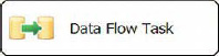
Figure 5-2. Data Flow task
The icon of this executable shows two cylinders with a green arrow pointing from one to the other. The first cylinder represents the source of the data, the green arrow represents the transformations, and the second cylinder represents the destination of the data. The icon may suggest that data can originate from one source, but the Data Flow task can extract data from multiple sources concurrently. Likewise, it supports outputting the data to multiple destinations simultaneously.
This component is covered in much greater detail in later chapters, as mentioned earlier. Some of its properties include the following:
DelayValidationdelays the validation of the metadata until runtime.
Disableprevents the execution of the Data Flow task during runtime.
MaximumErrorCountdefines the number of errors the Data Flow task can tolerate.
Descriptionprovides a short description of the Data Flow task.
Nameshows the distinct name of the Data Flow task.
DefaultBufferMaxRowsdefines the maximum number of rows that a buffer can hold. This property goes hand in hand with theDefaultBufferSizeproperty. Together they can solve some of the issues with a poorly performing Data Flow task.
DefaultBufferSizedefines the size in bytes of a buffer in the Data Flow task. Certain transformations within a Data Flow task create copies of existing buffers. This is covered in greater detail in Chapters 7 and 8.
RunInOptimizedModeoptimizes the data flow path by not allocating space for unused columns. Even though this property may be set toTrue, it will still give warnings about removing the columns from the Data Flow path.
TransactionOptionallows you to define whether the executable supports transactions. If the executable is called by a parent and transactions are enabled, the executable will be a part of the parent transaction. Mostly for performance reasons, we recommend that you leave this option set to the default.
Execute SQL Task
The Execute SQL task allows you to run SQL statements or execute stored procedures against an RDBMS by using various connection managers. The connection managers that the Execute SQL task can utilize are the Excel Connection Manager, OLE DB Connection Manager, ODBC Connection Manager, ADO Connection Manager, ADO.NET Connection Manager, and SQL Server Compact Edition Connection Manager. Figure 5-3 shows the executable as it appears in the control flow. The icon shows a cylinder with a scroll overlapping its bottom right. The cylinder represents a database system, while the scroll represents scripts. In this particular case, the script is a SQL script.
Figure 5-3. Execute SQL task
Execute SQL Task Editor—General Page
The Execute SQL task can be used to truncate tables before being loaded or to create constraints after the data has been loaded, to verify data integrity (DDL statements). The Execute SQL task can also be used to retrieve data and store it in SSIS variables (DML statements). The data retrieved can be a single row or a tabular data set. The Execute SQL Task Editor allows you to set up the executable to perform different functions. Figure 5-4 shows the General page of the Execute SQL Task Editor.

Figure 5-4. Execute SQL Task Editor—General page
The following list discusses some of the key properties on the General page:
Nameis a unique identifier for the task in the control flow. No two tasks of the same type can have the same name. This name is the label that is displayed in the control flow designer.
Descriptionis a text field that provides a short explanation of the task’s function in the package. Modifying this attribute is not required but can help those who are new to the package understand the process more easily.
Connectionis a required attribute that, by default, is blank . This value should indicate the name of the connection manager against which the SQL statement should be executed.
ResultSetallows you to define the type of the result that the query will return. There are four types of result sets:Single row,Full result set,XML, ornone.Single rowcan be used for singular scalar values or for tabular datasets that return only one row. TheFull result setoption allows you to store tabular data in an SSIS object type variable. If anORDER BYclause is defined in the SQL statement, the variable will maintain the data in a sorted list.XMLresult sets allow you to store XML data in a variable.Noneindicates that there is no result set returned. Successful executions of the SQL statements return values that indicate such. Mapping the result set to the appropriate variables can be performed in the Result Set page of the editor.
ConnectionTyperepresents the type of connection manager that you will use to connect to the database.
ConnectionManager is the name of the connection manager that will allow you to connect to the database.
SQLSourceTypedefines the method used to pass the SQL statement to the Execute SQL task. The choices areDirect input,File connection, andVariable.Direct inputallows you to type the SQL statement directly into the text field SQL statement. TheFile connectionoption allows you to specify a particular file that contains the query to execute.Variableallows you to assign a query to a string variable and pass it to the task.
SQLStatementcontains the SQL statements to execute on the indicated database. This field appears only ifDirect inputis selected as the source type of the query.
FileConnectionallows you to select a connection manager to source the SQL statements. This option is available only ifFile connectionis used as the source type.
SourceVariableis a list of variables that can store the SQL statements. This drop-down is available only ifVariableis selected as the source type.
SQLStatementcontains the DDL, DML, or DAL statements that need to be executed. When you modify the statement, a text editor opens in which you can type the statement. Without the text editor, you cannot place the GO on a new line and thus will have an error when you execute the package.
![]() NOTE: In order to execute DDL and Data Control Language, DCL, statements, you need to ensure that the credentials used have appropriate permissions. If you have multiple statements, only the first statement is allowed to return a result set.
NOTE: In order to execute DDL and Data Control Language, DCL, statements, you need to ensure that the credentials used have appropriate permissions. If you have multiple statements, only the first statement is allowed to return a result set.
![]() NOTE: We recommend using the semicolon (
NOTE: We recommend using the semicolon (;) statement terminator if you intend on executing multiple statements within a singular Execute SQL task. At the end of the statements, you can add the GO batch directive on a new line in the text editor. When setting up a result set, ensure that the query that returns the result set is the final query in the SQLStatement field.
The Browse button at the bottom allows you to import a query from a file into the SQLStatement field. It will open a Windows Explorer window to help navigate to the desired file. The Build Query button opens a graphical tool that assists you in constructing a query. This option is available only for the Direct input source type. The Parse Query button validates the syntax of the defined SQL query.
Execute SQL Task Editor—Parameter Mapping Page
Parameters allow you to pass variables to the SQL query that is to be executed. Depending on the SQL connection, the parameters use different markers and names for mapping. Table 5-1 shows the different markers, the associated names to use with the markers, and a sample query for each connection. The Parameter Mapping page in Figure 5-5 demonstrates parameterizing the SQL statement.

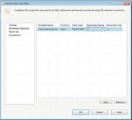
Figure 5-5. Execute SQL Task Editor—Parameter Mapping page
Multiple markers can be used throughout the query. The marker for ADO, ODBC, Excel, and OLE DB connections is a question mark (?). The enumerator for ADO and ODBC begins at 1. However, the parameter must be named with Param prefacing the ordinal position. The enumerator for Excel and OLE DB connections begins at 0. The ADO.NET connection is the only one that uses a qualifier (@) and name combination for the parameter mapping. The same variable can be passed to the same SQL statement multiple times.
To add a mapping for a parameter in the SQL statement, you need to click the Add button on the Parameter Mapping page. The columns on the mapping page specify all the details for each of the mappings. The Remove button simply removes the selected mapping. The properties are as follows:
Variable Name provides the particular variable that will be passed to the parameter in the SQL statement. The namespace of the variable is important because it allows for multiple variables to have the same name.
Direction indicates whether the variable is an input parameter, an output parameter, or a return code.
Data Type assigns a data type to the parameter. It does not automatically use the data type defined for the SSIS variable. The drop-down lists all the data types that are available to SSIS.
Parameter Name gives a name to the parameter. Depending on the connection type, you must name the parameter appropriately and make sure that the ordinal position of the marker in the query coincides with the name. The ordinal position plays an important role for this column when using some of the connection types.
Parameter Size defines the size of the variable length data types. This allows the provider to allocate the appropriate space for the parameter value.
Execute SQL Task Editor—Result Set Page
For SQL statements whose results need to be accessed by SSIS, we can assign those result sets to SSIS variables. One of the most frequently used result set types is the Full result set. This allows you to store the whole result, with a sort order if specified in the SQL statement, directly in a variable whose data type is defined as object. This object can be accessed by a Foreach Loop container to be used as the enumerator, by Script tasks in the control flow, or by a Data Flow task, depending on the scope of the variable. Figure 5-6 demonstrates defining the mapping for a result set of a query.
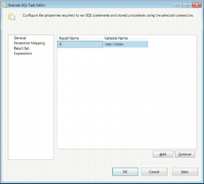
Figure 5-6. Execute SQL Task Editor—Result Set page
To assign values from the query to variables, you need to know the ordinal position or name of each column if the result set is a Single row; otherwise set the Result Name to 0. To add this assignment, you need to use the Add button. The results for a Full result set will automatically define the columns in the object. For Single row results, you need to make sure that the data type for each column is compatible with the mapped SSIS variable.
Execute SQL Task Editor—Expressions Page
The Expressions page allows you to define expressions that can change the value of the component’s properties. Multiple expressions can be defined for each component. Chapter 9 covers expressions further. Figure 5-7 demonstrates the Expressions page of the Execute SQL Task Editor.
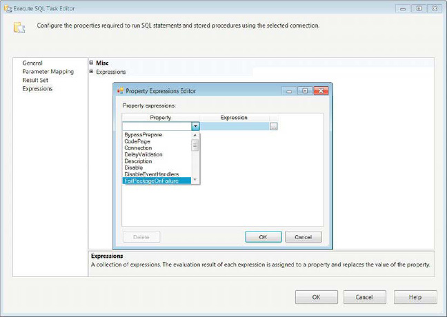
Figure 5-7. Execute SQL Task Editor—Expressions page
![]() NOTE: Henceforth, we will not display the Expressions page of task editors. Each of the properties that are accessible to the expressions may be unique to the particular task type, but there will be some overlap including
NOTE: Henceforth, we will not display the Expressions page of task editors. Each of the properties that are accessible to the expressions may be unique to the particular task type, but there will be some overlap including Name and Description.
Common Tasks
The Common grouping in the SSIS Toolbox contains some of the more commonly used tasks. These tasks perform operations that mainly support the ETL nonfunctional requirements. They can vary in operations such as preparing files for the ETL process to sending e-mails as a part of the package execution.
Analysis Services Processing Task
The Analysis Services Processing task allows you to process SQL Server Analysis Services (SSAS) objects. The objects include cubes, dimensions, and data-mining models. Figure 5-8 demonstrates the object as it appears in the control flow. This particular example shows the error message returned when a task is not connected to a cube. When you create an Analysis Services Processing task, you must point it to an SSAS database and add the objects you need to process. Without the objects added to the list, you will receive an error message.

Figure 5-8. Analysis Services Processing task
The icon for this task is a stack of cubes, with one cube alone on the outside. The cubes represent the SSAS database objects, specifically cubes. The single cube represents the measures as they can be sliced and diced by the different dimensions.
The objects added will be executed in a batch. The batch itself can be processed sequentially or in parallel. Generally, parallel processing will speed up the overall processing time. You have the option to define the number of objects that can be processed simultaneously, or you can let the task determine the objects. The dimensions are usually processed prior to the facts in order to prevent any missing key errors. The workaround for this is to allow processing to continue even with errors. It is a best practice to not ignore errors when processing a cube.
Analysis Services Processing Task Editor—General Page
The General page of the Analysis Services Processing task, shown in Figure 5-9, is extremely straightforward. It allows you to rename the executable and provide a short description of the task. The Name and Description properties will automatically reflect the values that are provided in the designer or the properties window. Only the Name property is modifiable in the designer window.

Figure 5-9. Analysis Services Processing Task Editor—General page
![]() NOTE: Henceforth, we will not show the General page of task editors unless the accessible properties include others besides simply
NOTE: Henceforth, we will not show the General page of task editors unless the accessible properties include others besides simply Name and Description.
Analysis Services Processing Task Editor—Processing Settings Page
The Processing Settings page of the Analysis Services Processing task, shown in Figure 5-10, allows you to specify your connection manager to the Analysis Services database and the objects you need to process. It also enables you to configure exactly how each of the objects can be processed.
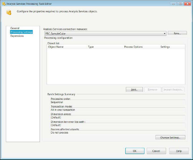
Figure 5-10. Analysis Services Processing Task Editor—Processing Settings page
The Analysis Services Connection Manager drop-down list provides all the existing Analysis Services connection managers in the package. The New button allows you to create one if it does not exist in the package already. The Object List section displays all the objects that are set to be processed by the task. These are examples:
Object Name specifies the name of the object to be processed.
Type displays the type of the object.
Process Options contains a drop-down of the processing options, which include Process Default, Process Full, Unprocess, Process Data, Process Index, and Process Update. Process Default, Process Full, and Unprocess are the only options available to all the object types. Process Default performs only the necessary tasks to initialize the object. The engine analyzes the state of the object to determine the best option to use. Process Full drops and rebuilds the object, updating the metadata as the object is being processed. Unprocess all the data that the object contains. Dimensions, cubes, measure groups, and partitions are the only objects with access to the Process Data and Process Index options. Process Data loads data into the objects without building indexes or aggregations. Process Index rebuilds only the indexes and aggregations without modifying the existing data. Process Update is available only to dimensions. It performs inserts, updates, and deletes on the dimensional data.
Settings provides the processing settings for the object.
The Add button allows you to add the objects in the database to the Object list. The Remove button deletes them from the list. The Impact Analysis button displays all the objects affected by processing the selected object. When the task performs the analysis, it takes into account the processing option that is selected. The impact analysis provides its own Object list of affected objects, which are as follows:
Object Name identifies the object that is affected by the defined object’s processing.
Type displays the affected object’s type.
Impact Type shows the effects of processing the selected object. The following impacts are shown: Object Will Be Cleared (Unprocessed), Object Would Be Invalid, Aggregation Would Be Dropped, Flexible Aggregation Would Be Dropped, Indexes Will Be Dropped, and Nonchild Object Will Be Processed. All except Object Will Be Invalid will provide an error message. The rest are simply warnings.
Process Object is a check box that allows you to add this object to the process object list.
The Change Settings button opens the dialog box displayed in Figure 5-11. It allows you to change all the settings displayed on the Processing Settings page.
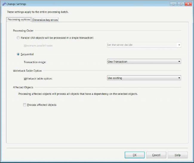
Figure 5-11. Processing Options tab of the Change Settings dialog box
In this dialog box, the radio buttons for Processing Order allow you to choose between processing the objects together or sequentially. When you are processing the objects together, you can either let the server decide the number of objects it can concurrently process or you can pick a number from the drop-down list. The numbers range from 1 to 128, doubling at each interval. When you process sequentially, you can choose to process the data as one transaction or many transactions, even the dependent objects.
The Writeback Table Option list allows you to choose the handling of the writeback table. This option is meant to record changes that occur to the data in the cube as it is being processed. There are three options available for writeback tables:
Create creates a writeback table if it does not already exist, throwing an error if it already exists.
Create Always creates a writeback table if it does not exist, or overwrites it if it does exist.
Use Existing uses the writeback table that already exists, throwing an error if it does not exist.
The Affected Objects section allows you to process the affected objects through a check box. This goes hand in hand with the Object list displayed by the Impact Analysis button.
The Dimension Key Errors tab, shown in Figure 5-12, allows you to change the processing operation’s error configuration. This Use Default Error Configuration option will use the server’s error configuration while processing. We recommend that you do not configure your own settings for processing unless there is a specific need to do so. Modifying this property may result in different outcomes than from processing a cube using an SSIS package than processing a cube through management studio.
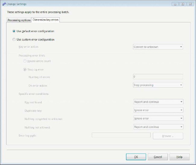
Figure 5-12. Dimension Key Errors tab of the Change Settings dialog box
The custom error configurations are divided into sections of possible errors and options for handling them. The different sections are as follows:
Key Error Action allows you to handle a new key that cannot be referenced in from the appropriate dimension. The two options to handle this error are Convert to Unknown and Discard Record. Convert to Unknown attributes all the data associated with this key to the unknown grouping. This functionality is similar to
COALESCE()orISNULL()in SQL. The second option, Discard Record, completely eliminates all data associated with this record in the object.Ignore Error Count enables you to ignore errors entirely while processing.
Stop on Error allows you to define the number of errors that the task can tolerate as well as the action to take after the tolerance is reached. The Number of Errors field specifies the number of errors that the task will support. On Error Action gives you two options in case the number of errors is exceeded, Stop Processing and Stop Logging. Stop Processing terminates the processing of the objects. Stop Logging stops logging errors but continues to process the data.
Specific Error Conditions gives you the flexibility to handle certain errors. The options to handle each scenario are Ignore Error, Report and Continue, and Report and Stop. Ignore Error simply continues without taking any action. Report and Continue reports the error but continues processing. Report and Stop reports the error and stops processing. The different conditions that cause errors while processing are Key Not Found, Duplicate Key, Null Key Converted to Unknown, and Null Key Not Allowed. The Key Not Found error indicates that a key was not found in the referenced data, usually a dimension. The Duplicate Key error is thrown when the same key references multiple attributes. Null Key Converted to Unknown occurs when null data is set into the unknown grouping. This is an error because null does not equal null and thus may break the integrity of the data. Null Key Not Allowed is a condition that occurs when the DDL does not allow null keys, but one is encountered when processing the data.
The Error Log Path option defines the file that stores the error log of the processing task. The Browse button allows you to navigate to the file location by using a Windows Explorer window.
Bulk Insert Task
The Bulk Insert task provides an extremely efficient option for EL processing. By circumventing the transform capabilities of the Data Flow task, the Bulk Insert task can quickly load vast amounts of data from a flat file source into a SQL Server table. This task supplies functionality similar to the BCP command available in SQL Server but imports data only into SQL Server. Figure 5-13 demonstrates what the component looks like in the control flow. The icon shows the database cylinder with some binary data overlapping it.
Figure 5-13. Bulk Insert task
Considerations Before Using the Bulk Insert Task
The source data file must exist on a server accessible by the host server, because it is the host server that will execute the Bulk Insert task. When accessing a remote server, Universal Naming Convention (UNC) must be used to indicate the file path and name. The task will use only the file’s connection manager for the location of the file. The delimiter information and the header row information needs to be specified to the task. A format file can be used in conjunction with the Bulk Insert task, but that file must exist on the server. Only an OLE DB Connection Manager can be used to connect to the destination database. The account used to execute the Bulk Insert task needs to have , system administrater, sysadmin, rights to the server. The Bulk Insert task will “map” the columns based on the order of appearance in the source file and the ordinal position in the table definition.
Bulk Insert Task Editor—Connection Page
The Connection page of the Bulk Insert Task Editor allows you to define the source and destination of the data, as well as the format of the source data file. The connection for the destination must be an OLE DB Connection Manager. To specify the format information, you can either define it directly in the task itself or you can point the task to a format file stored on the file system. The Format list enables you to choose the formatting options. RowDelimiter provides the character combination that marks the end of a data row. ColumnDelimiter allows the task to identify the character combination that signifies the end of a column. Even though you may have defined the format information on the file connection manager, it will be ignored by the Bulk Insert task, as Figure 5-14 demonstrates. The File is a drop-down list of all the file connection managers that exist in the package.
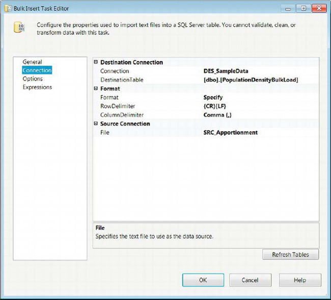
Figure 5-14. Bulk Insert Task Editor—Connection page
Bulk Insert Task Editor—Options Page
The Options page of the Bulk Insert Task Editor allows you to define the properties of the actual process itself. The configuration enables you to specify properties of the source as well as the destination. As Figure 5-15 shows, the options are divided into two groups: Advanced Options and Options.
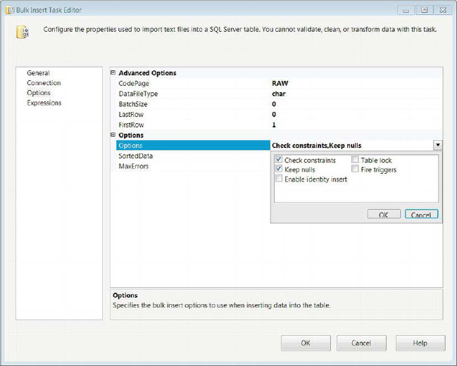
Figure 5-15. Bulk Insert Task Editor—Options page
Following are the options and what they control:
CodePageidentifies the code page of the source data in the file.
DataFileTypedefines the data type to use during the load into the destination.
BatchSizedefines the number of rows per batch. The default value,0, indicates that the entire load operation should be part of one batch.
LastRowpoints to the last row to import into the destination. The default value,0, indicates that the end of file (EOF) should determine the last row.
FirstRowpoints to the first row to import into the destination. This value will allow you to ignore header rows. It is important to skip the first row if it contains the names of the columns.
Optionsdefines some of the integrity checks that can be performed during the bulk insert. Check Constraints ensures that all the constraints defined on the table are not violated. Keep Nulls inserts nulls into the table columns as they appear in the source, despite any default values defined on the table. Enable Identity Insert allows you to insert values into an identity column. Table Lock performs locking operations on the table as it is being loaded by the bulk insert. Fire Triggers allows any triggers defined on the table to be executed.
SortedDataprovides a comma-separatedORDER’ed BYclause of column names as they appear in the destination table. This specifies that the values are sorted in the source.
MaxErrorsdefines the error tolerance of the Bulk Insert task. The value0indicates that an infinite number of errors are allowed to occur. Any row that cannot be imported is considered an error.
Data Profiling Task
The Data Profiling task allows you to quickly get statistically significant information on tables or views in a database. This task can be used to determine foreign-key relationships, candidate keys, or even null ratios of columns. The information about the data can then be loaded into a flat file in XML format or an SSIS variable. Figure 5-16 shows the component as it appears in the control flow. The icon of bar charts indicates statistical information. The Data-Profiling task contains statistical information such as ratio of uniqueness for a possible candidate key or ratio of null data in a column.
Figure 5-16. Data Profiling task
Data Profiling Task Editor—General Page
The General page of the Data Profiling Task Editor asks you to determine the destination for the data profile information. In Figure 5-17, we chose to store the information in a flat file that will be overwritten each time the task is executed. We would like to point out that unlike the General pages of some other tasks, this one does not allow you to provide a Name and a Description.
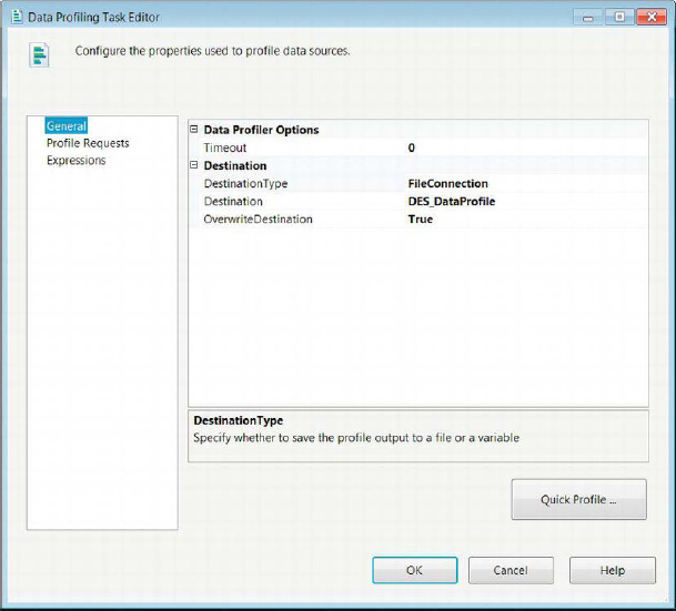
Figure 5-17. Data Profiling Task Editor—General page
Instead of allowing you to modify the Name and Description properties, the General page of the Data Profiling Task Editor provides the following properties for modification:
Timeoutallows you to define the amount of time for the task to stop running.
DestinationTypeprovides a drop-down list that allows you to input the data-profiling information in either a variable or a flat file.
Destinationlists all the Flat File Connection Managers that are defined in the package. If none have been created or the specific destination isn’t connected to, you can create a new one.
OverwriteDestinationallows you to overwrite the file if it already exists. The default value isFalse, appending the information to the file.
The Quick Profile button opens the dialog box shown in Figure 5-18. It allows you to quickly define the information you need to collect on a given database. The Quick Profile Dialog windowallows only one table or view per. After you select all the information that needs to be computed, the selections are imported to the Profile Requests list. The Data Profiling task connects to the database by using an ADO.NET connection. After selecting the connection, you can specify the table or view to profile. The check boxes allow you to profile specific information. We discuss the details of each option in Chapter 12.

Figure 5-18. Single Table Quick Profile Form dialog box
Data Profiling Task Editor—Profile Requests Page
The Profile Requests page of the Data Profiling Task Editor, shown in Figure 5-19, allows you to configure the options for each of the profile requests. The All Requests list shows the Profile Type and the Request ID of each request. The View drop-down allows you to filter the requests by profile type. Information such as the ConnectionManager and the TableOrView values are imported from the Single Table Quick Profile Form. The RequestID is automatically generated but can be modified after it has been added to the Profile Requests page. The ThresholdSetting option allows you to set the type of threshold you want as the success criteria of your profile. Using this field will allow you to discover keys that are nearly unique. The MaxNumberOfViolations property can define the number of duplicates or failures of the key you want to tolerate.

Figure 5-19. Data Profiling Task Editor—Profile Requests page
Execute Package Task
One of the most flexible ETL design patterns uses one package to call other packages. This design requires the use of the Execute Package task, an executable that allows a package to call another package as a part of its execution. The original package’s variables can be accessed by the called package. The original package can also pass along any parameters that have access to it. Figure 5-20 shows the component in a control flow. Its icon is a file with blue squares—three on the file, and one outside it. The three blue squares represent executables contained within the file itself, and a single square outside the file indicates access to executables outside the immediate package.
Figure 5-20. Execute Package task
Execute Package Task Editor—Package Page
The Package page of the Execute Package Task Editor allows you to specify the location and name of the package. The location of the package can be indicated by accessing the project that the current package belongs to. This will populate the PackageNameFromProjectReference list with all the packages contained within the current project. Figure 5-21 shows the task utilizing the project to reference the package. This ETL design pattern is called parent-child design. We cover it in more detail in Chapter 16.
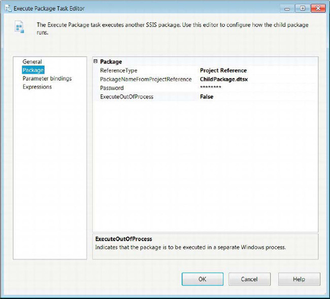
Figure 5-21. Execute Package Task Editor—Package page
Depending on the ReferenceType required, the properties that appear on the Package page will vary, with the exception of ExecuteOutOfProcess and Password. The properties are as follows:
ReferenceTypeallows you to select the location of the package.Project Referenceindicates that the child package exists as an object within the current project.External Referenceallows you to access a package on the file system or SQL Server.
PackageNameFromProjectReferencelists all the packages that are a part of the current project. This property is available only with theProject Referencetype.
Passwordis the password that is used to encrypt the child package. Even though in Figure 5-21 it appears that there is a password, the package is not encrypted. By default, SSIS fills in this field. Clicking the field opens a dialog box that asks you to specify and verify the password.
ExecuteOutOfProcessspecifies that the package can be executed as a new Windows process.
Locationdefines whether the package exists on the file system or SQL Server. This property is available only for theExternal Referencetype.
Connectionspecifies the connection manager to use to access the package. For the file system location, the connection lists all the file connection managers defined in the package. The SQL Server location lists all the OLE DB Connection Managers created in the package.
PackageNameappears only for packages stored on SQL Server. It opens a dialog box that allows you to pick a package that exists on the server.
PackageNameReadOnlyimports the value from the file connection manager used to connect to the package.
Execute Package Task Editor—Parameter Bindings Page
To facilitate the new deployment model, parameters are allowed to be passed between the parent and child packages. Figure 5-22 shows the Parameter Bindings page that allows you to specify the parameters to pass on to the child package. The Add button adds bindings to the task. The parent package will connect to the specified package and read in all the defined parameters. For the example in Figure 5-22, we created two parameters, ParentCreatorName and ParentStartTime, in ChildPackage.dtsx. The parameters can be added in the Parameters and Variables window. As with the variables, you have to specify a name and data type for the parameter. The parameter does not have a namespace as variables do.
This is a new functionality added to this version of SSIS. In the prior versions, configurations had to be added to the child package to pass variable values by reference. The parameters allow you to pass values from the parent to the child packages without adding explicit configurations to the child packages. The parameters are a part of the execution of the child packages. This is useful when you deploy packages to different environments and each environment requires a different set of values of the variables or connection strings of the connection managers.
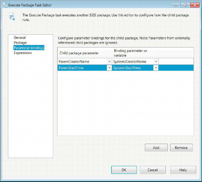
Figure 5-22. Execute Package Task EditorParameter Bindings page
![]() TIP: If the Execute Package Task Editor does not automatically detect the parameters defined in the child package, we recommend saving your changes, closing Visual Studio, and reopening the parent package. This lack of automatic detection can occur if you add new parameters to the child package while the parent package is open.
TIP: If the Execute Package Task Editor does not automatically detect the parameters defined in the child package, we recommend saving your changes, closing Visual Studio, and reopening the parent package. This lack of automatic detection can occur if you add new parameters to the child package while the parent package is open.
Execute Process Task
One of the most useful functionalities of SSIS is its ability to perform tasks that are not strictly ETL. One of the tasks that allow this functionality is the Execute Process task. This executable allows you to call batch files or applications from within the package. This task can also run command-line utilities or other applications. It even provides properties that will accept parameters that should be used when calling the process. Figure 5-23 demonstrates this task in the control flow. The icon for this task is an application window, showing that the purpose of this task is to run other programs. This task can be used to run dtexec.exe to call another package, but those packages will not be run in the Visual Studio Debug mode.
Figure 5-23. Execute Process task
![]() NOTE: If user input is required when the package is executed through SQL Server Agent, the package will fail.
NOTE: If user input is required when the package is executed through SQL Server Agent, the package will fail.
The Execute Process Task Editor’s Process page, shown in Figure 5-24, allows you to pass in all the relevant information necessary to run the external process. It also allows you to pass outputs from the execution to SSIS variables. In the sample shown in Figure 5-24, we simply use the findstr utility in Windows to pull the lines that have the string New and store the results in the User::ProcessOutput variable. The modifiable properties for the Execute Process task are as follows:
RequireFullFileNameallows you to fail the task if the executable does not exist in the specified file path. We strongly recommend that you define the path and not rely on the Windows path being set. This will avoid deployment issues in different environments. The path itself can be set through the Expressions page by modifying variables according to your needs.
Executablespecifies the process you need to run. You can specify the complete path in this field.
Argumentsare passed to the executable.
WorkingDirectorydefines the folder path to the executable. The Browse button will open a Windows Explorer dialog box to assist you in defining the path. If there is a chance the path may vary from environment to environment, we recommend using an expression to set this property.
StandardInputVariableuses a variable to provide an input to the executable.
StandardOutputVariablespecifies a variable to store the output of the process.
StandardErrorVariablespecifies a variable to store the error output of the process.
FailTaskIfReturnCodeIsNotSuccessValuespecifies whether to fail the task if the return value of the process does not match theSuccessValueproperty.
SuccessValueis the value that the process will return to indicate a successful execution.
TimeOutrepresents the number of seconds tolerated for the execution of the process. The default value,0, indicates that the process can no limit defined.
TerminateProcessAfterTimeOutis available only if aTimeOutvalue is specified. If set toTrue, the process will terminate if theTimeOutvalue is reached.
WindowStylerepresents the style of the window during the execution. The choices for the style areNormal,Maximized,Minimized, andHidden.
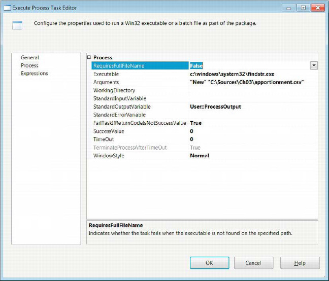
Figure 5-24. Execute Process Task Editor—Process page
File System Task
For certain ETL projects, files from the file system are used for data sources or as controllers of a project. To allow for manipulating the file system in order to handle these files appropriately, SSIS has the File System task. This task, shown in Figure 5-25, performs manipulations on files and directories. The icon for this task shows two files demonstrating the elements of this task’s operations.

Figure 5-25. File System task
The File System Task Editor’s General page, displayed in Figure 5-26, allows you to configure the operations you need the task to perform. The task will dynamically change the properties available for editing, depending on the operation selected. In the sample that we demonstrate, we simply copy one file to another location.
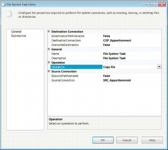
Figure 5-26. File System Task Editor—General page
The available properties for the File System task are as follows:
IsDestinationPathVariablespecifies whether the path for the destination of the operation is static or in an SSIS variable.
DestinationConnectionuses a file connection manager’s connection string to specify the location of the destination. This property is available in the editor only ifIsDestinationPathVariableis set toFalse.
DestinationVariableuses an SSIS variable to specify the location of the destination. This property is available in the editor only if theIsDestinationPathVariableis set toTrue.
OverwriteDestinationdefines whether the operation will overwrite existing files in the destination directory.
UseDirectoryIfExistsdefines whether the operation will fail when the specified directory already exists. This property is available in the editor only when the selected operation isCreate directory.
IsSourcePathVariablespecifies whether the path for the source of the operation is static or in an SSIS variable.
Namedefines the name of the specific task.
Descriptionis a text field that briefly summarizes the task’s objective.
Operationlists the file system processes the task can perform.Copy directorycopies the whole source directory to the destination path.Copy filecopies the source file to the specified destination path.Create directorycreates a directory in the specified location.Delete directorydeletes the specified directory.Delete directory contentdeletes all the contents of the specified location.Delete filedeletes the specified file.Move directorymoves the source directory to the destination specified.Move filemoves the source file to the destination path.Rename filerenames the source file to the specified destination name.
Set attributesallows you to modify the attributes of the specified source file.Hiddenallows you to specify whether the source file should be set to hidden.ReadOnlyallows you to set theReadOnlyproperty of the specified file.Archiveallows the specified file to be archivable.Systemallows you to set the file as a system file.
FTP Task
The FTP task allows you to connect to an FTP server to download or upload files that you require for your ETL processes. In addition, it allows you to perform some of the same operations as with the File System task, but on the server instead of the file system. Figure 5-27 shows the task as it appears in the control flow. The icon for this task is a globe with a server tower in front of it, indicating a file system that can be accessed remotely.

FTP Task Editor—General Page
The FTP task uses an FTP Connection Manager or a variable containing the server information to connect to the FTP server. For more information about the FTP connection, refer to Chapter 4. The task will connect to the server at runtime and carry out the specified operation. Figure 5-28 shows the FTP Task Editor General page.

Figure 5-28. FTP Task Editor—General page
The following list describes all the properties available on the General page:
FtpConnectionlists all the FTP Connection Managers defined in the package. This manager will be used to connect to the server.
StopOnFailureallows the task to fail if the FTP process fails.
Nameallows you to specify the name of the FTP task so that it may be uniquely defined.
Descriptionallows you to provide a brief summary of the task’s objective.
FTP Task Editor—File Transfer Page
The File Transfer page of the FTP Task Editor, shown in Figure 5-29, allows you to define the properties necessary to carry out the selected operation. This page, which is very similar to the General page of the File System Task Editor, dynamically changes the properties available for editing depending on the operation selected.

Figure 5-29. FTP Task Editor—File Transfer page
Following is the full list of possible properties:
IsLocalPathVariabledefines whether the location of the local file is stored in a variable or can be accessed by using aa defined File Connection Manager.
LocalPathlists all the file connection managers created in the package.
LocalVariablelists variables that store the file path.
Operationlists the operations that can be performed by the FTP task.Send filessends the file specified in the local location to the remote location.Receive filesdownloads the file specified in the remote location to the local location.Create local directorycreates a directory in the path specified in the local location.Create remote directorycreates a directory in the path specified in the remote location.Remove local directorydeletes the directory specified in the local location.Remove remote directorydeletes the directory specified in the remote location.Delete local directorydeletes the specified file in the local location.Delete remote directorydeletes the specified file in the remote location.
IsTransferAsciispecifies whether the transfer between the local and remote locations is in ASCII mode.
IsRemotePathVariablespecifies whether the remote file path is defined in a variable or FTP Connection Manager.
RemotePathlists all the FTP Connection Managers created in the package.
RemoteVariablelists variables that store the remote location.
Script Task
One of the best ways to manipulate the objects in the package is a Script task. The Script task can use Visual Basic or C# in order to extend the functionality of the SSIS package beyond the provided tasks and connection managers. The Script task in the control flow is different from the Script task in the Data Flow task in that it modifies package-level objects, whereas the data flow Script task handles the data at the row level. Figure 5-30 shows the Script task as it appears in the control flow. Its icon looks like the Execute SQL task’s icon, but without the cylinder representing a database. The scroll icon indicates that the purpose of the task is to process a script. We have a whole chapter dedicated to scripting, Chapter 9.

Figure 5-30. Script task
As we mentioned, the Script task allows you to extend the processes that SSIS components have natively. One of those advantages is the ability to access the .NET libraries. Certain libraries can give you access to the file system and perform tasks that are beyond the functionality of the File System task or the Execute Process task. Figure 5-31 demonstrates the Script page of the Script Task Editor. In this particular example, we simply open a message box displaying the value of a variable at runtime. This technique is helpful when you are tracing an issue and are unsure of a variable’s value.
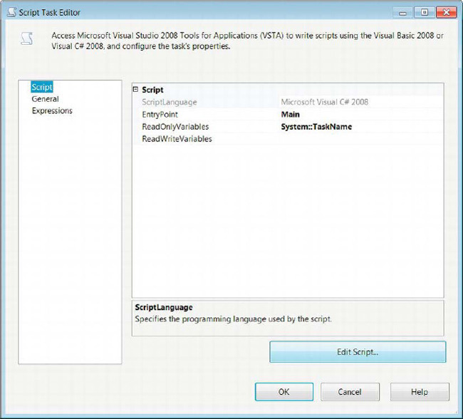
Figure 5-31. Script Task Editor—Script page
The following properties are configurable on the Script page:
ScriptLanguageallows you to choose between Visual Basic and C# as your scripting language. Chapter 9 weighs the pros and cons of using each language.
EntryPointdefines the initial method SSIS calls at runtime. By default, it is themain()method inside theScriptMainclass. Because the major code blocks are automatically generated when you initially create the task, you don’t need to worry about the basic references.
ReadOnlyVariablesis a comma-separated list of all the variables to which you want the script to have read-only access. Without all the variables specified, you will run into an error when you try to refer to its properties in the script. By clicking the ellipsis, you can open a dialog box that will display all the variables available to the scope of the Script task. After you select the variables you want to access in the script, you can import them into this property.
ReadWriteVariablesis a comma-separated list of all the variables to which you want the script to have read/write access. You can populate this field in the same way as forReadOnlyVariables.
The Edit Script button opens a script editor. The first time you open the script, it will automatically include the proper assemblies and create some default classes and methods. The script editor is based on the Visual Studio Tools for Applications (VSTA). Figure 5-32 shows the script editor with some of the prepopulated code and comments. The initial code block provides access to all the necessary assemblies. The only modification we made to this code is in the main() method. We added a line of code that pops up a message box showing you the value of a specific variable. The line of code is MessageBox.Show(Dts.Variables[“System::TaskName”].Value.ToString());. The MessageBox.Show() method creates the message box. The method’s parameter, Dts.Variables[“System::TaskName”].Value.ToString(), accesses the Variables collection of the package. It is important to make sure that the variable is in scope for the Script task and that it is at least provided as a ReadOnly variable, as shown earlier in Figure 5-31.
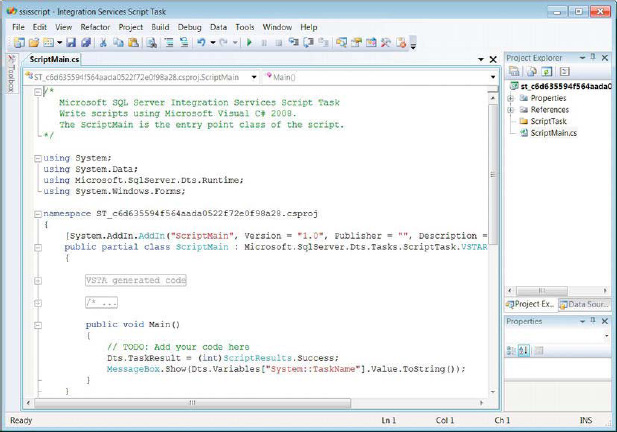
Figure 5-32. Visual Studio Tools for Applications—script editor
When we execute this package using the Visual Studio Debug mode, we receive a message box displaying the original value of the variable because there was no change performed on it. The System::TaskName variable contains the name of the current task. We can assign values to ReadWrite variables by using C# or Visual Basic assignment operations. We discuss scripting in great detail in Chapter 9.
Send Mail Task
It is often the case that managers and database administrators would like to know when a process fails unexpectedly. ETL processes are not exempt from this requirement. SSIS provides a task that can send e-mails by using a mail service. It requires an SMTP Connection Manager in order to connect to a mail server. SSIS allows only Windows Authentication and anonymous authentication. For more about the connection manager, refer to Chapter 4. In Figure 5-33, we demonstrate the task as it appears in the control flow. The icon is a stamped envelope with a return address and mailing address, indicating all the necessary components for the task.

Figure 5-33. Send Mail task
The Mail page of the Send Mail Task Editor, shown in Figure 5-34, allows you to configure all the properties you need to send an e-mail. One of the key features of this task is the ability to attach files. You can output your logging to a file to attach to an e-mail before you send it off to provide context for the failure.
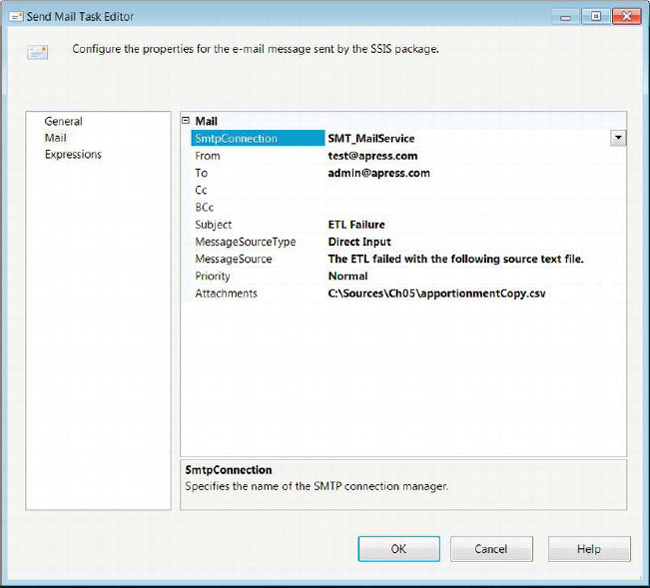
Figure 5-34. Send Mail Task Editor—Mail page
The following list describes all the properties that can be configured:
SMTPConnectionspecifies the SMTP Connection Manager to use in order to send out the e-mail.
Fromdefines the sender’s e-mail address.
Tolists the recipients of the e-mail, using semicolons to separate the different e-mails.
Ccdefines the carbon-copy recipients of the e-mail. This list separates each e-mail address with a semicolon.
Bcclists the blind-carbon-copy recipients of the e-mail. This list is separated by using semicolons as well.
Subjectprovides the subject of the e-mail that is to be sent out.
MessageSourceTypelists the options for the body of the e-mail message. The three options areDirect input,File connection, andVariable.Direct inputallows you to type in the message directly. TheFile connectionoption lets you choose a file connection manager to the file that will contain the body of the e-mail. TheVariableoption allows you to select an SSIS variable containing the body of the e-mail.
MessageSourceis populated based on the source type that is selected. TheFile connectionandVariableoptions open a dialog box that lets you select the connection manager or variable you wish to include as the message body. WithDirect input, you can directly type in a message.
Prioritydefines the priority of the e-mail message. The options areLow,Medium, andHigh.
Attachmentslists the different files to attach to the e-mail. The files are separated by the pipe character. This field, unlike other instances, does not utilize a file connection manager but rather a file path as it exists on the file system of the executing machine.
Web Service Task
Another key point of versatility of SSIS is its ability to connect to a web server and execute methods against using web services. The Web Service task utilizes the HTTP Connection Manager to accomplish such requirements. Figure 5-35 shows the task in the control flow. The task’s icon is similar to that of the FTP task, except that the Web Service task icon does not have an image of a server overlapping the globe. The globe icon indicates that the task’s operations are done against a remote service.
Figure 5-35. Web Service task
Web Service Task Editor—General Page
The General page of the Web Service task allows you to define the connection information necessary to connect to the web server. This is done mainly through the HTTP Connection Manager that needs to be defined before the rest of the properties of the task can be set. Figure 5-36 displays the General page of the task’s editor.
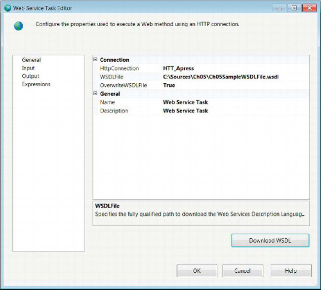
Figure 5-36. Web Service Task Editor—General page
The available properties are as follows:
HTTPConnectionlists all the HTTP Connection Managers defined in the package. Just like the FTP connections, the HTTP connections support only Windows authentication and anonymous authentication.
WSDLFileprovides the full path for the Web Services Description Language file that you need to use in order to execute methods against the web server. The file contains the methods available to the web service and their parameters. The file must exist in the defined path at runtime. At design time, you can create a new file with the.wsdlextension and use the overwrite property to download it from the web services.
OverwriteWSDLFilespecifies whether you should overwrite the file from the web server. This option allows you to download the latest file from the web server and overwrite the local copy of it.
Namespecifies the name of the Web Service task.
Descriptionprovides a short explanation of the task’s objective.
Download WSDLuses the HTTP Connection Manager to download the WSDL file from the web server. This button is enabled only when a local file path is provided.
Web Service Task Editor—Input Page
The Input page of the Web Service task allows you to specify the method on the web server and its parameters. The task will use the specified HTTP Connection Manager to call the method. It will use the WSDL file in order to populate the drop-down lists shown in Figure 5-37.

Figure 5-37. Web Service Task Editor—Input page
The following properties can be configured on the Input page:
Serviceis a drop-down list of the web services available. Select the one required to execute the method.
Methodpicks a method from a list that the web service can execute.
WebMethodDocumentationprovides a description of the web service method that is being called. The ellipsis button allows you to type a multiline description.
Namelists the names of the method’s parameters.
Typelists the data type of the method’s parameters. The Web Service task supports primitive data types such as integers and strings.
Variablelists the variables that will store the values for the input parameters.
Valueallows you to type in the value directly.
XML Task
SSIS can be used in various operations on Extensible Markup Language (XML) data. The data can be stored in the form of variables or files, or even directly inputted. The task that is provided to handle these operations is the XML task. The results of the operations can be outputted into a file for review or further processing. Figure 5-38 shows the task as it appears in the control flow. The icon is a globe contained within tags denoting the markup format of the language.

Figure 5-38. XML task
The General page of the XML task, shown in Figure 5-39, allows you to configure all the necessary properties. Depending on the type of operation, the editor will dynamically change to allow for only the necessary properties to appear. One necessary component of the task is the XML input.

Figure 5-39. XML Task Editor—General page
The available properties are as follows:
OperationTypedefines the type of operation that the task will perform. The choices areValidate,XLST,XPATH,Merge,Diff, andPatch.Validatecan compare a source input against Document Type Definition (DTD) or an XML schema definition.XLSTwill perform Extensible Stylesheet Language transformations on the sources.XPATHwill perform XPath queries on the sources.Mergewill compare two inputs, taking the first input and then adding the content of the second to the first.Diffcompares the two inputs and writes their differences to an XML diffgram file.Patchtakes an XML Diffgram and applies it to a source input and generates a new document that has the contents of the Diffgram.
SourceTypedefines whether the XML is retrieved byDirect input,File connection, orVariable.
Sourceenables you to input XML directly into the text field if theSourceTypewas set asDirect input. For file connection or variable sources, this option is a drop-down list of connections or variables that can be used.
SaveOperationResultallows you to save the results of the operation on the XML source.
DestinationTypeallows you to save the results of the operation in either a file pointed to by a connection manager or a variable.
Destinationlists all the available file connections or variables to store the output, depending on the destination type selected.
OverwriteDestinationspecifies whether you want to overwrite the existing value of the destination with the new output.
SecondOperandTypedefines whether the second XML input isDirect input,File connection, or aVariable.
SecondOperandlists all the available connections or variables, depending on the operand type selected.
ValidationTypelets you select betweenDTDandXSD.DTDwill use a Document Type Definition, whereas theXSDwill allow you to use an XML Schema definition as the second operand. This property is available only with theValidateoperation.
FailOnValidationFailwill fail the task if the execution returns a failure. This property is available only with theValidateoperation.
PutResultSetInOneNodeallows you to place the results of the XPath operation into one node. This property is available only with theXPATHoperation.
XPathOperationallows you to select the XPath result set type. The different result set types areEvaluation,Node list, andValues.Evaluationreturns the results of an XPath function.Node listreturns certain nodes as XML.Valuesreturns only the values of the selected nodes as one concatenated string.
XPathStringSourceTypedefines the type of source that will identify the merge location in the first XML input. The choices areDirect input,File connection, andVariable. This property is available only with theMergeoperation.
XPathStringSourcepoints to the string that will identify the merge location of the XML input. This property is available only with theMergeoperation.
DiffAlogrithmlists the types of algorithms available for the generation of the Diffgram. TheAutooption allows the XML task to determine the best algorithm for the operation.Fastallows for a quick but less-accurate comparison. ThePreciseoption allows for more-accurate results at the cost of performance. This property is available only with theDiffoperation.
DiffOptionsrepresents the options available when attempting to perform theDiffoperation.IgnoreXMLDeclarationallows you to ignore the XML declaration.IgnoreDTDallows you to ignore the DTD.IgnoreWhiteSpacesignores the amount of whitespaces when comparing documents.IgnoreNamespacesallows you to ignore the Uniform Resource Identifier (URI) of the XML.IgnoreProcessingInstructionsallows you to compare multiple processing commands.IgnoreOrderOfChildElementsallows you to compare the order of the child elements.IgnoreCommentsdefines whether the task will ignore comment nodes.IgnorePrefixesdefines whether or not you compare the prefixes of the elements and attribute names.
FailOnDifferencedefines whether the task will fail if it encounters a difference between the XML inputs.
SaveDiffGramallows you to save the Diffgram that is generated as a result of the comparison operation.
DiffGramDestinationTypeallows you to choose the method of saving the generated Diffgram through either a file connection or a variable.
DiffGramDestinationallows you to pick between defined file connection managers or variables in the package to store the Diffgram.
Precedence Constraints
After you add executables to the control flow, you have the option to define the order of execution. The order of execution is dictated by the precedence constraints that you define. When you don’t define any constraints, the executables will execute at the same time, as is the case with the Execute Process task and the Data Profiling task. To add a precedence constraint, click the task and then click and drag the arrow to the task that should execute next. After you have an arrow connecting the tasks, you can right-click the arrow and select a type from the menu; the default constraint is Success. Constraints can be defined on tasks, containers, and event handlers.
There are three types of precedence constraints. The first constraint, denoted by a green arrow, is the Success constraint. It allows the constrained executable to run only if the preceding executable completed successfully. The second constraint, denoted by a blue arrow, is the Completion constraint. The Completion constraint allows the constrained executable to run only if the precedence executable completed its execution. The Completion constraint does not distinguish between a successful execution and one that returns an error. The third constraint, denoted by a red arrow, is the Failure constraint. The Failure constraint will run the constrained executable only if the preceding executable returns an error. The precedence constraint can be configured to use expressions as well. Figure 5-40 shows the Precedence Constraint Editor.
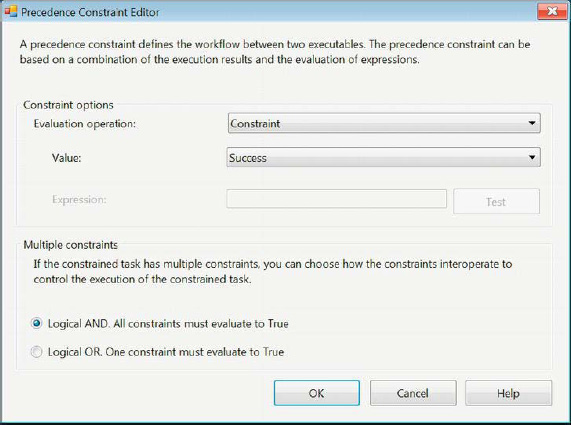
Figure 5-40. Precedence Constraint Editor
The Precedence Constraint Editor allows you to configure properties specifically regarding the execution of the constrained executable. The following are the configurable properties:
Evaluation Operation specifies the constraining element of the constrained executable. The options for this property are
Expression,Constraint,ExpressionAndConstraint, andExpressionOrConstraint.Expressionindicates that the constrained executable will execute only when the expression evaluates toTrue. TheConstraintoption will allow the executable to be constrained only by the constraint’s value.ExpressionAndConstraintwill require the results of the constraint and the evaluation of the expression to allow the execution of the executable. TheExpressionOrConstraintoption will require either the constraint or the expression and expression to evaluate toTrue or FALSE.Value defines the constraining element of the executable. The prior executable’s execution has to evaluate to this value in order for the constrained executable to execute. The options for this property are Completion, Success, and Failure.
Multiple Constraints specifies the conditions of the executable’s execution if it is constrained multiple times. The two options are Logical
ANDand LogicalOR. These options will either perform a logicalANDor logicalORbetween all the constraints specified in order to execute the constrained executable.
For the sample shown in Figure 5-41, the Execute Process task and the Data Profiling task will execute at the same time. The Script task will execute only if the Execute Process task executes successfully. The Bulk Insert task will execute after the Execute Process task completes its operations. The Send Mail task will execute only if the Execute Process task fails in its execution. At any given execution, you will have the combination of the Script task and the Bulk Insert task, or the combination of the Send Mail task and the Bulk Insert task, executing at the same time because those tasks are constrained by only the Execute Process task.
![]() NOTE: An executable can constrain multiple executables as well as be constrained by multiple executables. The type of constraints can vary as well. This will allow an executable to run only if certain execution results are achieved. An executable cannot constrain or precede itself.
NOTE: An executable can constrain multiple executables as well as be constrained by multiple executables. The type of constraints can vary as well. This will allow an executable to run only if certain execution results are achieved. An executable cannot constrain or precede itself.
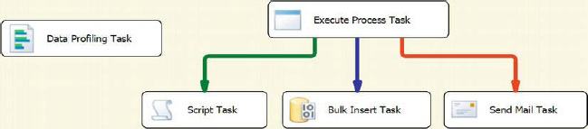
Figure 5-41. Precedence constraints and parallel tasks
Basic Containers
Adding many tasks to the control flow can make reading the SSIS Package difficult. One of the ways that we can avoid cluttering the control flow is by utilizing the containers. The containers allow you to group together multiple tasks and even other containers. There are three types of containers that SSIS provides: For Loop container, Foreach Loop container, and Sequence container. This section introduces the Sequence Container. The other two, we leave for Chapter 6. There is one other method of organizing that is present within SSIS, and that is grouping. It is not a container in the strictest sense, but it allows for the package to be visually readable.
Containers
All three containers are organized in the SSIS Toolbox in the Containers folder by default. They can be moved to the Favorites and Common groups. Containers modularize SSIS packages. They can be used to limit the scope of variables so that you can define variables for access only by tasks and containers contained within the parent container. The scope of a variable is a part of the variable definition and exists in a column in the list of variables in the Parameters and Variables window. The executables within a container create a subroutine within the package. The tasks defined within a container cannot initiate the execution of a task or container outside the container. The arrow at the right of the container’s name allows you to collapse the contents of the container for configuration.
![]() TIP: Using containers frequently within your packages gives you the ability to execute all the objects within the container in Visual Studio’s Debug mode. You cannot execute the entire package but rather just the executables within the container. To do this, you can simply right-click the container and select Execute Container. In order to access Debug mode, the package needs to be opened as a part of a project.
TIP: Using containers frequently within your packages gives you the ability to execute all the objects within the container in Visual Studio’s Debug mode. You cannot execute the entire package but rather just the executables within the container. To do this, you can simply right-click the container and select Execute Container. In order to access Debug mode, the package needs to be opened as a part of a project.
Figure 5-42 demonstrates a potential use of a Sequence container. The icon for the container is a blue square outline containing a solid blue square and a blue arrow. The icon shows several potential executables being contained by the container. The Execute Process task is the first task to execute, and then the constrained Script task will execute only if the first task executes successfully.
![]() NOTE: The sequence containers support the
NOTE: The sequence containers support the Transaction property, allowing Execute SQL tasks to execute as a single transaction.
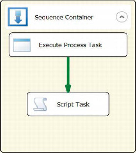
Figure 5-42. Sequence container
Groups
Groups in the SSIS control flow are not containers, but they offer some of the organizing advantages that containers offer. We do not recommend using groups because they can lead to SSIS spaghetti code. Unlike containers, groups do not isolate the executables within them. They allow precedence constraints to be created between objects inside and outside the group, as shown in Figure 5-43. In this example, we have an Execute SQL task preceding a Data Flow task. It appears as if the Data Flow task and File System task should execute together, but in reality the Execute SQL task and the File System task will execute at the same time. Just like containers, groups can collapse the objects they contain.
![]() NOTE: Groups do not allow you to execute the objects they contain. They merely allow you to visually organize the objects.
NOTE: Groups do not allow you to execute the objects they contain. They merely allow you to visually organize the objects.
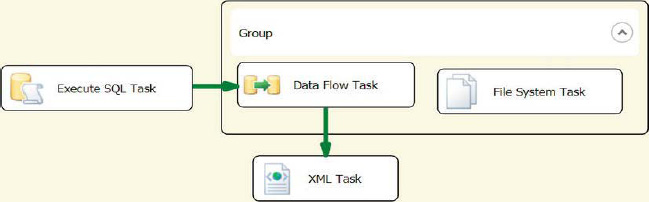
Figure 5-43. Groups
Breakpoints
During the execution of the objects in a package, each executable fires events. Visual Studio’s Debug mode allows you to create breakpoints that will listen for these events and suspend the execution. Breakpoints can be defined on tasks, containers, and the package as a whole in the control flow. To create breakpoints, you have to right-click the object and select Edit Breakpoints. This selection opens the dialog box shown in Figure 5-44.
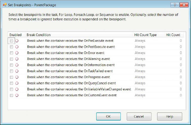
Figure 5-44. Set Breakpoints options
This dialog box allows you to specify the Break Condition, the occurrence of the condition that will increment the count, and the count that will be tolerated before the execution is suspended. This section introduces the events that SSIS issues. We discuss them in greater detail in Chapter 11. The events are as follows:
OnPreExecutecreates an event right before the target object starts execution.
OnPostExecutecreates an event right after the target object completes execution.
OnErrorcreates an event when the target object causes an error during execution.
OnWarningcreates an event when the target object is not in a state to error but it is not designed optimally.
OnInformationcreates an event when the target object issues information about the execution.
OnTaskFailedcreates an event when the target object fails execution.
OnProgresscreates an event when the target object is in the middle of executing.
OnQueryCancelcreates an event when the target object is stopped in the middle of executing.
OnVariableValueChangedcreates an event when a variable value changes during the execution of the target object.
OnCustomEventcreates an event when there are custom events that the target object raises during execution.
The Hit Count Type column in the Set Breakpoints dialog box defines the criteria that causes the target object to suspend its execution. The options are Always, Hit Count Equals, Hit Count Greater Than or Equal To, and Hit Count Multiple. The Always hit count will always suspend the execution of the target, every time the enabled break condition event is raised. This option disables the Hit Count column. The Hit Count Equals option will suspend the target only if the condition event is raised enough times to match the defined hit count. The Hit Count Greater Than or Equal To option will suspend the execution every time the condition event is raised, starting when the number of event occurrences matches the hit count. The Hit Count Multiple option will cause the target to suspend its execution every time the break condition event is raised enough to be a multiple of the defined hit count.
Summary
This chapter introduced the basic control flow items that will enable you to utilize some the connection managers introduced in Chapter 4. The control flow designer window uses the SSIS Toolbox to add executables. These executables and containers are organized in groups that can be customized for your development habits. This chapter introduced the Favorites and the Common groups. Precedence constraints define the order and conditions in which the objects execute. Containers can be used to modularize the packages. This chapter presented the sequence container. Breakpoints can be used in the Debug mode, depending on the events the target objects raise. Chapter 6 covers the remaining tasks and containers.