Get to know Revit's basic commands, tools, and techniques. The faster you learn to work with the interface, the more productive you'll become. With the new interface, most tools appear when an object is selected; however, some tools are located on the Modify tab. As you progress using Revit, you'll find that certain commands are better suited for certain tasks. For example, you'll develop a sense of when to copy and paste an element versus when to move and copy it; and when to use the spacebar instead of the Rotate tool. You will also get acquainted with the Join Geometry tools, the Split Face and Paint tools, and Revit's keyboard shortcuts.
In this chapter, you'll learn to:
Knowing how to select, modify, and replace elements of a Revit building model is fundamental to working with the software. These basic interface operations are the building blocks that you'll use throughout the process of making edits to your model.
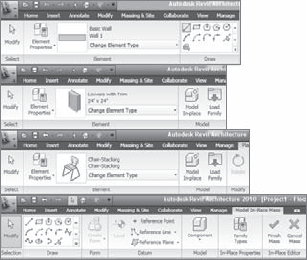
Selection is straightforward in Revit: hover your cursor over an element and it highlights (turns purple); click the highlighted element, and it turns blue, meaning you have it selected. Once the item is selected, a special contextual ribbon tab appears that contains the tools relevant to the selected command or context (Figure 3.1).
You can select multiple elements in several ways:
- Additive selection
Hold down the Ctrl key while clicking new elements to add them to your selection. To remove elements from the selection, hold down the Shift key and click the selected elements.
- Window selection
You can select many elements by dragging a selection window across the view. Do this by holding down the left mouse button and dragging. A left-to-right drag selects only elements completely within the selection window; a right-to-left drag selects anything within or intersecting the selection window.
- Chain selection
You can select connected lines and walls by placing your cursor over a line or wall (don't pick, just let it highlight) and then holding down the Tab key and selecting a wall or line. All walls/lines that are end-joined to that wall become selected.
- Selection Count tool
The selection count tool is displayed on the far right in the same zone as the status bar; its icon is a filter because it actually is an addition to the selection filter functionality and gives information about the number of Revit elements currently selected.
After making a selection of elements, you can see the number of elements you selected by double-clicking the count icon. This invokes the Filter dialog box, where you can narrow down your selection if needed. If you have nothing selected in the model, double-clicking on the count icon will not invoke the Filter dialog box.
You can also access the selection count tool by directly invoking the Filter dialog box from the Multiselect tab. This box is only active after you have made a selection of multiple different categories of elements in the model. Note that if you select elements of one category, the filter option does not exist
Try this out on any model you have open. Using a box selection, draw a big box around a portion of your model, and then click the Filter button from the Multiselect tab. You'll get a dialog box like the one shown in Figure 3.2. Here, you can deselect categories to limit what you've selected. Think of this as a shortcut. Let's say you need to change the properties of 20 doors in a plan view. It's much faster to box-select an area of your model and then filter out all the elements except the doors than it is to Ctrl-select all 20 doors one at a time.
This option is available in the context (right-click) menu of an element and allows you to select all instances of a particular family in the entire model. This is great when you need to perform a wholesale swap of a certain family throughout the entire model. For example, if you placed some generic wood doors in your project and you now want to swap all those with metal doors, this command is perfect. To use it, select one door in the model, right-click, and choose Select All Instances from the context menu to select all the wood doors. Then, select Change Element Type, which invokes the Type Selector in the Modify tab, to change the door type. With this command, elements become selected that may not be visible in your view (the elements might be hidden), because this type of selection isn't limited to what you see or have manually clicked. Remember that you're selecting all instances of that family type used in the entire model.
Whenever you make a selection of elements, you can look at the count tool on the bottom right of your screen. Figure 3.3 shows that four elements were selected.

The best practices to model a building in BIM are to start to model using generic walls, floors, doors, and windows, and then over time, as you make more specific decisions and refine the details of the design intent, swap those for specific types of elements. Using Revit, you don't have to redraw elements when you decide to get more specific with your design. You make new types or load new content, and then swap out the elements using the Change Element Type (that invokes the Type Selector) in the Modify tab. The elements listed are all of the same category, making it easy to locate relevant content.
You can take advantage of this feature the moment you start placing any Revit families. During creation, you can use the Change Element Type tool to choose the type of element being placed. Once you select an element, the same list becomes available, making it simple to change the types.
Be careful when you use this tool with walls, because not only does it change the wall type, but it also changes the top and bottom constraints of the walls being matched. Thus, the best practice for walls, if you need to change the type but don't want any of the level constraints to change, is not to use the Match Type tool but instead to use the Change Element Type button (Type Selector) from the Modify Walls tab that becomes available upon selection of a wall.
Copying and pasting is a familiar technique used in almost all software applications, and Revit provides the basic features you'd expect with a copy and paste interaction (Ctrl+C and Ctrl+V). It also has some additional time-saving options that are specific to working on a 3D building model.
Once you've copied elements to the clipboard, you can paste them into other views with a variety of options. This allows you to quickly duplicate elements from one view to another (an entire furniture set from one floor to another floor, for example) while maintaining a consistent location in the X–Y coordinate plane. After selecting elements and copying them to the clipboard using either Ctrl+C or the Copy button in the Clipboard Panel of the Modify tab, choose Edit

Five options are available. Depending on the view from which you copy and what elements you copy, the availability of these options will change. For example, if you select a model element in a plan view, you'll have all the options shown in the figure. The options are as follows:
- Select Levels
This is a mode you can use to copy and paste elements between different levels. Once you select the elements and choose this option, you choose levels from a list in a dialog box, and you can paste to multiple levels at once. This is useful when you have a multistory tower design and you wish to copy and paste a furniture layout that repeats on 20+ floors; in such a case, selecting levels graphically in a view can be tedious. The X–Y position of the selected elements is maintained, and the pasted elements are translated in the vertical dimension.
- Select Views
This option allows you to copy elements to other views by selecting views from a list of views in a dialog box. In the list available for selection, you don't see levels listed but rather a list of parallel views. For example, if elements are copied from a plan view, all other plan views are listed. Likewise, if you copy from an elevation view, only elevation views appear as possible views to paste into.
- Current View
This pastes the elements from the clipboard into the currently active view, in the same relative spatial location. For example, if you copy a series of walls in one view, switch to another view in the Project Browser, and choose Current View, Revit pastes the walls into exactly the same X–Y locations in the new view you switched to.
- Same Place
This option places an element from the clipboard in the exact same place from which it was copied or cut. One use for this tool is copying elements into a design option; see Chapter 10, "Working with Design Options," for an explanation of design options.
- Pick Levels Graphics
This is a mode you can use to copy and paste elements between different floors. Once you select the elements and choose this option, you're placed into a pick mode where you can select a level in section or elevation. You must be in an elevation or section view to have this option available. The level you select determines the Z location of the paste and preserves the X–Y location. You might use this type of paste to copy balconies on a façade from one floor to another.

The Create Similar tool is available in the Create panel of the Modify tab when an element is selected. You can also access the tool from the right-click menu. To use this tool, think about the type of element you need to make, and select an instance of it. Then, click the Create Similar tool, and you'll immediately be put into placement–creation mode. If you use this tool later to create a similar floor or roof (or any other sketch-based element), you're taken directly into sketch mode, where you can start sketching your new element.
Revit provides a range of options to interactively edit elements in the model. The most obvious is to select elements to drag around the screen or use the blue control grips to extend walls and lines. However, you often need more precise ways of moving and positioning things. Let's look at some ways to do this.
Revit provides several ways to move elements, ranging from traditional tools to intelligent dimensions that appear on the fly when you select elements. Become familiar with each method, and find what is best for your workflow.
You should have noticed by now that when elements are selected, dimensions appear. These dimensions are called temporary dimensions and are there to both inform you of the location of the elements relative to other elements in the model and help you reposition the elements. Clicking the blue dimension value makes it an active, editable value. Type in a new value and the element that was selected will move to that point. Keep this in mind: when editing a position of an element via the dimensions, it will always be the selected element that moves. By the same token, you can't edit a dimension if nothing is selected.
If a temporary dimension isn't referencing a meaningful element, you can choose a different reference by dragging the small blue square attached to the dimension witness line to a new parallel reference (Figure 3.5). Parallel references highlight when you mouse over them. For example, if you want to position a door opening at a specific dimension from the wall, you will need to drag the blue dot reference that currently references the door middle axis to the door opening so that the temporary dimension can read that distance and you can further edit to the value you wish. Parallel references highlight when the cursor moves over them.

If you click a blue grip, it cycles to the next possible reference in the element. For example, clicking the blue grip of a dimension to a door or window cycles between the left and right openings and the center of the element. The same is true for walls: try clicking the blue grip control of a temporary dimension that appears when you select the door, and see how the temporary dimension cycles through the various references in the wall (interior face, centerline, exterior face).
To change which references temporary dimensions go to first, use the Temporary Dimension Properties dialog box shown in Figure 3.6 (Manage tab

If you have many elements selected at the same time, temporary dimensions sometimes don't appear. Check the Options bar for the Activate Dimensions button; clicking it will make the temporary dimensions appear in the view.

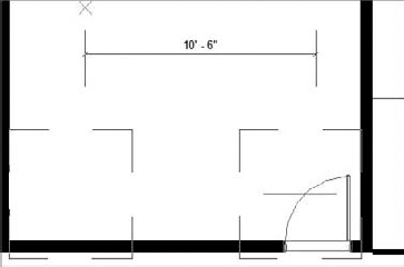
Moving elements is a two-click process: first you define a start point, and then you click to define an endpoint. If you know you need to move something to the left 10′−6″, it doesn't matter where your two picks take place; all that matters is that the distance between the two clicks is 10′−6″. (Figure 3.7 shows the graphics provided during a move operation.)
There are a few options on the Options bar to be aware of when the Move command is active.
- Constrain
When this option is selected, it constrains movements to horizontal and vertical directions. Deselecting it gives you free movement if the element is freestanding. Hosted elements such as windows and doors always move in a constrained manner parallel to their host axis.
- Disjoin
Hosted elements such as windows and doors can't change host and move to another host without explicitly being disjoined from their host. This option lets you disconnect inserts from their host and move them to new hosts. For example, if you need to move a door from one wall to another, you select the door, select the Move tool, select Disjoin on the Options bar, and move the door to another host.
- Copy
This option lets you make a copy of the element without moving the original element. In the strictest sense, this isn't really a move operation but a shortcut to making a copy.
- Multiple
This option, which is selectable only after you pick the Copy option, lets you make multiple copies of the selected element.
Nudging is a great way to push things around quickly. When an element is selected, you can use the arrow keys on the keyboard to move the element horizontally and vertically, repositioning it in small increments. Each press of an arrow key nudges the element a specific distance based on your current zoom factor. The closer you zoom, the finer the nudge is. Likewise, as you zoom out, the nudge moves elements by larger increments. This is a good tool when you're working with views placed on sheets.
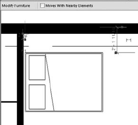
Another way to move freestanding elements, but in a more automatic way, is to use the Moves with Nearby Elements feature. This tool is designed to capture logical relationships between elements. When furnishing a space for example, you probably want to align the bed or dresser with a wall. If you change your design, you want the furniture to follow the wall to the new location. For this purpose, select the furniture and then select Moves with Nearby Elements on the Options bar. By doing so, you create an invisible relationship between the bed and the wall so that each time you move the wall, the bed moves with it (Figure 3.8).

To activate this tool, first choose the element or elements you want to copy, and then select the Copy tool from the Modify tab. Using the Options bar, you can choose to make multiple copies in one interaction by selecting the Multiple option.
It's common to need to rotate an element. Just as with Move, Revit provides a few methods for rotating elements. The time-saving spacebar is a quick way to rotate elements in 90-degree increments. Just press the spacebar when an element is selected; each press of the spacebar will rotate the element another 90 degrees. If a diagonal reference (wall, grid, or reference plane) is nearby, then the spacebar will locate this as a rotation candidate. For more precision, the Rotate tool is provided, which you can use to rotate elements to any specific angle you require.
Revit uses the spacebar to rotate elements both at the time of placement and after an element has been placed. This is a great timesaving command to become familiar with, because you can forgo using more traditional tools such as Rotate and Mirror by taking advantage of the spacebar. Here are a few examples:
- Doors and windows
If you have a door with its swing in the wrong direction, select it and press the spacebar. You can cycle through all four possible orientations of the door with a few clicks. The same holds true for windows; however, many window families are built to only let you flip the window from inside to outside, because many windows are symmetrical in elevation. If you are creating an asymmetrical window on your own, be sure to add flip controls to the window family during its creation. These allow the spacebar to work on hosted elements. Figure 3.9 shows the window opened in the Family Editor and where to access the flip controls for placement from the Create tab.
- Walls
If you select a wall, pressing the spacebar flips the element as if it were being mirrored about its length. Walls flip based on the Wall Location Line, which often isn't the wall centerline. If you aren't sure which direction your wall is facing, select it and look for the flip-control arrows. These are always drawn on the exterior side of walls (Figure 3.10).
- Freestanding elements
If you select a freestanding element like the loveseat shown in Figure 3.11, the spacebar rotates the element about the center reference planes defined in the family. Depending on how the family was built, the rotation origin may not make the most sense, but you can quickly orient your furniture and casework. If you decide to edit a family to change the location of the geometry relative to the center reference planes, be careful: when loaded back into a project, all your elements will jump to a new X–Y location based on the changes you made!

You'll notice that while moving the origin, you lose the ability to pan and zoom the view. To overcome this, drag the origin into the Project Browser and release the mouse button; then, move the cursor back into the view. The cursor changes to a rotation icon, and you can freely pan and zoom all you want. The next click you make places the origin, and you can then designate the rotation.

You can create two types of array: linear and radial.

If you want to arrange elements in a fixed space, and the exact spacing between elements is a less important factor, use the Last option. Figure 3.14 shows an array where the location of the last element in the array was picked, and the elements (in this example, windows) were placed equally between the first and last elements in the array. With this option, the length is fixed, and the array squeezes elements within that constraint as the number changes. The examples in Figures 3.14 and 3.15 show that depending on your design criteria, you can use different arrays.

Figure 3.14. This array uses the Last option and backfills instances between the first and last group.
A radial array works in a similar fashion, but it revolves around a center point. With a radial array, elements auto-rotate so that each element faces the center of the array, as shown in Figure 3.15.

Figure 3.15. When you're making a radial array, you can specify the number of instances interactively.
Enabling the Group and Associate option allows you to treat an array as a group that can be modified later to adjust the number and spacing of the array. If this option is unchecked, then the array is a one-off operation, and you have no means of adjusting the array after you create it.
When an element in a grouped array is selected, a control appears, indicating the number of elements in the array. Editing that number changes the number of elements in the array. This tool comes in handy when you're creating certain families, because the array number can be parameterized. See the section "Parametric Arrays in the Family Editor" in Chapter 11, "Moving from Design to Documentation," for a detailed exercise.

This tool is also well suited for working with imported images that need to be scaled to match real-world dimensions. For example, it's common to import an aerial photograph of a site to use as a contextual underlay. The Scale tool works great to get the image to the right scale. You also can create a formula in the element properties of an image to rescale it very specific requirements.
This tool is active once you select an image. After you select the Scale tool, click a point to enter an origin (say, the lower-left corner of the image); click a second point to determine the width of the image that you want to fit within a certain size; finally, click a third time to get the new length you want.
Important note: Keep in mind that you're working with a building information model (BIM) made out of real-world objects, not abstract primitive forms. Don't expect to be able to scale most elements in Revit—it's not practical or meaningful. For example, you can't scale the size of a door, wall, or sink because they represent real-life types and scaling them would mean scaling all their components. This would probably lead to impractical or even meaningless results—for example, the door frame will scale in unreal proportions while the size of the panel might be still right.

With this tool, you explicitly align references from one element to another. For example, you can align windows in a façade so their centers are all in alignment. You will find the Align tool in the Modify tab, under the Edit panel. To use the Align tool, you will first select the target reference (a part or side of the element to which you want to align another element) and then select what you want to align to that reference (the part or side of the element whose position needs to be modified). The second element picked always moves into alignment. This selection sequence is the opposite of the other editing tools we've looked at so far, so remember: first you select the aligning reference, and then you select the element to move into alignment with the reference.
As soon as you make your second pick, a lock icon appears so you can constrain the alignment. Once you click the lock icon, if either element moves, it brings the constrained element along with it.
Figure 3.17 shows the use of the Align tool to align windows on a façade. The left opening of the topmost window was used to align multiple windows using the Multiple Alignment option on the Options bar.
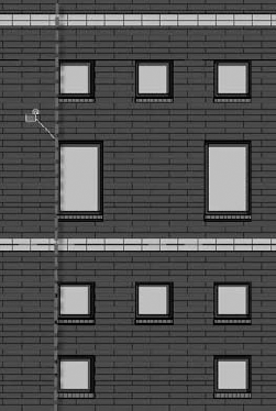
The Align tool also works for aligning geometry with surface patterns like brick or stone. Select a line in the surface pattern, and then select the geometry you want aligned. Figure 3.18 shows how you can align the edge of a window to a brick pattern. Use the Tab key if you cannot get surface patterns selected with the first mouse click. The align tool will also rotate elements in the process of aligning them to objects which are not parallel. This is a real time saver compared to rotating and moving.

The Trim tool, which is called Trim / Extend to Corner, trims elements to one another, creating a cleaned-up end join between walls and lines. For example, Figure 3.19 shows two walls before and after using the Trim/Extend to Corner tool.

The Trim tool is used a lot for editing sketches of floors and roofs, because it's easy to end up with overlapping lines that need to be neatly trimmed. Keep in mind that with the Trim tool, you're selecting pairs of elements to remain, not be removed. Use the temporary preview graphics to help you. If you do trim the wrong thing, you'll see it immediately—just undo, and pick again.
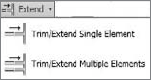
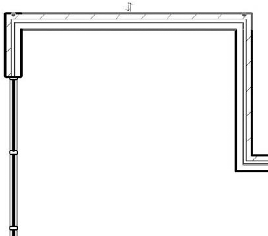
This tool lets you extend single or multiple instances of lines and walls. The first option, Trim/Extend Single Element, is for extending a single wall. To extend a wall, first select a target wall; then select the wall you want to extend to that target (Figure 3.20). The second option, Trim/Extend Multiple Elements, lets you extend many walls in one interaction.

The Options bar offers a nice feature called Delete Inner Segment that removes the need to use the Trim tool. In Figure 3.21, you need to remove the middle section of the wall and end up with a clean set of wall joins. Using the Split tool with the Delete Inner Segment option checked, you can accomplish this with two clicks and get a clean condition without having to come back and use the Trim command

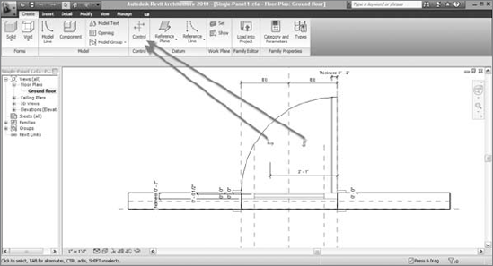
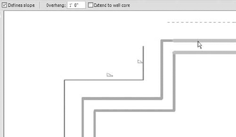
This tool is especially useful in the Family Editor when you're making shapes that have a consistent thickness in profile, such as extruded steel shapes. Offset is also handy when you're making roof forms or soffits with known offsets from a wall. You can either offset a line and maintain the original (for that, make sure that the Copy option in the Options bar is checked) or offset the line, removing the original. Figure 3.22 shows roof creation done by offsetting the sketch lines in the Roof Editor where the offset has been defined as 1′−0″. Each pick of the wall offsets the line by 1′−0″.
In many cases, you'll want to make sure some elements in the model never move. A good example of this is when you work on a renovation of an existing building. You surely would not like to move walls that already are built somewhere else in the model. Other examples are imported drawings, grids, levels, and exterior walls (once their position is set). Revit provides two ways to deal with this and lock certain elements preventing them from moving.
This tool is located in the Modify panel of the Modify tab. Select the element you want to pin down and click the Pin tool. If you try to move the element, nothing will happen—you won't even get a ghost preview of a potential move. To unpin an element, select it and look for the pin icon. Clicking the pin removes it and frees the element. The Unpin All tool is essential for unpinning multiple elements rather than selecting and unpinning one at a time.
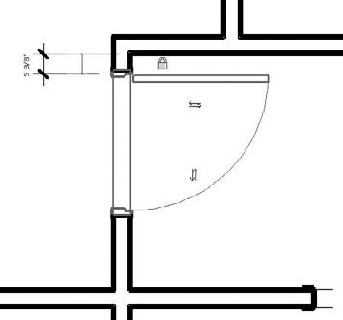
A simple example of using constraints is keeping a door a fixed distance from a side wall, so that if the wall moves, the door also moves. If you do try to move the door, Revit will not let you do it. Look at Figure 3.23: the door has been locked to remain 5⅜″ from the wall face. This is done by selecting the door and locking the padlock that appears next to the temporary dimension defining the position of the door to the wall. After locking the padlock and thus creating a constraint, if the wall moves, the door moves as well; but if you try to drag the door to a new location, you can't.
Another example is locking the head height of a series of windows relative to a level. This prevents users from accidentally dragging windows into undesired locations while guaranteeing that if the level moves, the windows also move.
A range of other editing tools are available in Revit, and these will be covered in subsequent chapters when they're used in specific operations. There are a few tools you should know about now, however, because they're generic tools that you can put to use on any project immediately. These tools, which will help you produce the drawings you need, have the added benefit of being intelligent and parametric.


To fix this condition, select the Join Geometry tool, and then select the floor and wall in sequence.
You should be aware that joining host elements across a large model created significant regeneration issues. One way to avoid this is to apply the following workaround: Give a black solid fill to elements in the cut plane of your sections – and then selectively join for medium and fine views. Solid host elements also read better in section at smaller scales (like half-size sets).

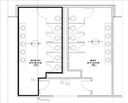
Figure 3.25 shows the floor that initially covered both of the restroom spaces being split with the Split Face tool. Once the face has been split, you can activate the Paint tool to apply material to it.
The Type Selector lists all the materials in your project (Figure 3.26).

Choosing a tile material and then clicking the split face applies the material. The result is that the floor is unchanged structurally, and the bathroom appears with a tile finish (Figure 3.27).

Many users like using keyboard shortcuts to speed up common commands and minimize the need to interrupt workflow. When you hover your cursor over any tool in the ribbon, the keyboard shortcut is indicated to the right of the tool name, as shown here.

Revit contains preset keyboard shortcuts when installed, but you can modify the default shortcuts by editing the Keyboard.txt file located in the C:Program FilesRevit Architecture 2010Program folder. Revit's shortcuts are two-key shortcuts and are available only for commands that already exist. When you change the shortcuts in the Keyboard.txt file, Revit shows these abbreviations in the menu.
- Select, change, and replace elements
Learning the basic mechanics of the interface is crucial to just about everything you'll do in Revit.
- Master It
Selecting elements in the model happens all the time. What are some of the capabilities that the Revit user interface provides when you select elements?
- Edit elements interactively
The architectural process inevitably involves revision, so be sure you know how to make changes on the fly.
- Master It
You need to make some major changes to a floor plan, moving the bathroom 20′ down a corridor. How might you do this with Revit?
- Use other handy editing tools
Revit provides a wide range of tools for making changes in a project.
- Master It
In a section view, you notice that the walls and floors aren't cleaning up neatly—you're seeing lines overlap. What tool could you use to try to clean that up?