
In this chapter we explore how to build your own designed library elements (families) for use in a project. We'll look at how parametric constraints and parameters can be used to build flexible, timesaving, beautiful, and smart content. By learning a few simple rules in addition to the form-making principles that we covered in Chapters 6 ("Modeling Principles in Revit, Part 1") and 7 ("Modeling Principles in Revit, Part 2"), you can build just about any element and assign it a behavior that you wish it to have—all without writing one line of code or knowing a programming language. Building intelligent content is a key feature of Revit and deserves an entire book in its own right, but we will introduce you to some useful concepts and get you going. This chapter will take you through fundamental principles and some compelling use cases using the Family Editor.
In this chapter, you'll learn to:
Model parametric 3D families
Nest one family into another
Build relationships between parameters with formulas
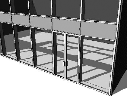
As a design progresses from generic to more refined, you'll need to add more detail and realism to your model. This process involves more faithfully representing what will be built and requires you to start building your own families. Although many types of families are provided out of the box, additional families can be downloaded from websites such as seek.autodesk.com www.revitcity.com, or www.arcat.com. You'll inevitably reach a point where your design intent isn't matched by any of those, and you'll need to create new elements yourself. This is when you'll need to dig into the Family Editor and create new building components (Figure 11.1).
Up to now we've covered many of the basic principles of families, including understanding the different family categories, the principles of modeling, form making, and constraints—but we haven't put all this into practice beyond some simple shapes. In the following sections, we'll look at more advanced techniques used to create parametric families with embedded intelligent behaviors.

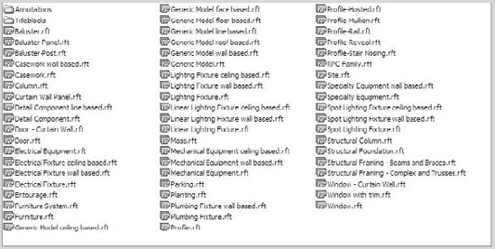
Every family belongs to a category, and it is essential to categorize new families correctly so they can be controlled and scheduled logically when you load them and use them in a project. Choosing the correct family template when making new families will set the appropriate category. Revit provides templates (see Figure 11.2) for most families. These are hard-coded, and you cannot create a new template from scratch. Don't regard this as a limitation, since there is a template for all major necessary architectural elements, and those few rare elements for which you might not find a corresponding template can be created using the generic template.
When you decide to create an element on your own, you need to select the correct template. These templates are time-savers, because they already have the right category assigned, provide the most important reference planes that drive the behavior and geometry, and in some cases include text notes to help explain how the family will work in the context of a project. Figure 11.3 shows a window template file, which includes text indicating the exterior and interior of the wall; parametric dimensions for width, sill height, and opening height, and a sample host wall. This is the template to start with when you've designed a new custom-shaped window, for example.
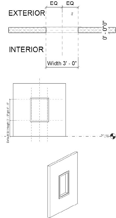
Figure 11.3. Plan, elevation, and 3D views of a template for windows. Text notes, reference planes, and dimensions have been preset.
The reference planes that appear in the family environment are the essential "bones" of any family. They establish the critical dimensional rules for the family, define the origin, and provide references that can be dimensioned to when loaded into a project. Without reference planes, you can't make parametric content or dimension it in the project. Fortunately, all templates provide at least two reference planes to start with.
At the highest level, families occupy two categories: those that will appear in one view only (drafting, annotation, 2D families) and those that, when placed in a model, will appear in any view (model-based).
For model-based families, there are two high-level types: 2D families are used for making 2D details of the model, and 3D families are for making 3D geometric representations.
For 2D families, you can make standard detail components and line-based (2-pick) detail components. Three-dimensional family types include various host-based types (floor, wall, roof, and ceiling), profiles, line-based, work plane-based, and generic model. Note that 3D families can contain nested 2D elements as a way to embed more detailed information about that element directly into the families. Two new templates were added to 2010 that provide a custom set of tools for making conceptual masses. These are the Mass and Curtain Panel Pattern Based templates.
Choosing the correct template is essential to getting the desired family categorization and behavior of the element you are creating. To better understand what that means, let's drill deeper into family types.
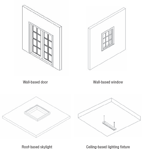
Windows, doors, skylights, and lighting fixtures are all discretely manufactured objects, but they have something in common: they're installed into something else. Without the wall, ceiling, or any other mounting surface, the object has no place to ground itself in a typical building project. In other words, these types of elements require a host in which they can be placed or by which they can be supported. For these types of elements, Revit provides host-based families and templates.
When you need content to have an explicit relationship with a wall, floor, or roof, then a host-based family is absolutely the way to go. This is the most common type of family used in Revit. A host-based family includes components such as doors, windows, skylights, solar panels, light fixtures, and balusters. If you are reading this, you've probably placed some windows and doors in a Revit project, so we will not cover the benefits and behaviors of host-based families in detail here. If you are new to Revit, or need a refresher, don't worry. The basic principles are quite simple: once a host-based element is placed in or on a host, a dependency arises between the element that requires a host and the host in which it is placed. In an example of a wall (host) and window (host-based family), if you move the host, the hosted element will move as well; if you delete the host, the hosted element, too, will be deleted. Bear this in mind going forward in developing your model. Figure 11.4 shows several examples of such host-based families.
The golden rule when making a new family is to first consider it from a category point of view. What am I making? How does it need to behave (in a view or schedule, 2D or 3D, parametric, limited parameters, etc.)? Once it's made, how might it need to change, if at all? Then you can use an appropriate template as a starting point. For example, if you need to make a new window, start with the Window.rft template. Similarly, if you are making a table, the Furniture.rft template is the way to go.
Windows and doors don't exist in the model in isolated, abstract form, but are always hosted by a wall. This is why when you start creating or editing a window family, you will see a sample host element (a small wall, roof, or floor). The sample host in the family is there just to help you construct the family so it behaves properly in the model. It gives you a context in order to build the family so it correctly relates to wall thickness.
Many architectural details have distinct cross sections that run in a closed, linear fashion. Revit constructs these details by extruding that profile along a path, a process that is similar to how many of these elements are physically manufactured. Baseboards, cornices, handrails, and mullions are all good examples of profile-based elements:
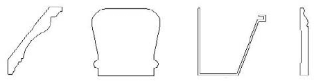
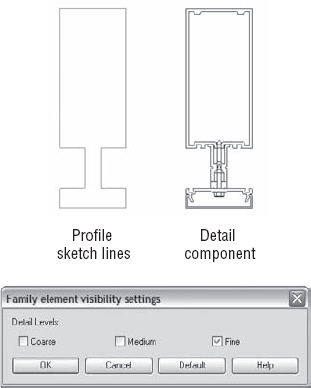
Revit provides special templates designed for elements like these. To create one of these elements, you need to create a Profile family. You will notice that there are a few different profile family templates to choose among: Hosted, Mullion, Rail, Reveal, and Stair Nosing. Make sure you pick the correct one when creating a profile family. Once you select a template, you can start sketching with 2D lines, defining the shape of the profile cross section. Like many sketches in Revit, the profile must be made of a single closed loop of lines. Multiple loops will lead to errors downstream. For example, if you created a mullion profile like that shown in Figure 11.5 and then tried to load it and use it in a mullion family, you'd get a warning message. Delete the inner loop of lines to get the mullion to work properly.

Figure 11.5. This profile is invalid because profiles with more than one loop won't work in a project.
If this is true, you must be asking yourself how you can make something like the shape shown in Figure 11.5. Although you can't have multiple loops in the profile family, you can import a detail component into the profile family that will mimic the representation you need; this is possible because there is no penalty for having multiple loops of lines in the detail component. The detail family showing the rest of the content within the outer profile adds much more detailed information about that element. It can be visible in a section of that element in the model (think plan and section views), and you can decide in which levels of detail you want that detail component to be visible.
To control when this level of detail will be visible in the model, set the visibility of the detail component so it appears only at fine levels of detail. Continuing with the mullion example, take these steps:
Start a new family using the
Profile Mullion.rftfamily template.Load a complex detail component done by a manufacturer into the mullion profile family. You will find a myriad of them on the Web, usually offered in DWG format, although with every passing day more manufacturers offer their content in
.rfaformat as well.Trace the loaded component with a single loop of lines to get the outer shape of the profile (see Figure 11.6).
As you probably don't need to see such complexity at the coarse or medium level of detail (it will probably just print as black blobs in your drawings in small scales), set the options in the Visibility Settings dialog box to show the detail only in fine views.
Load the Profile Mullion family into the project by using the Load into Project button.
From the Project Browser, under the Curtain Wall Mullions node, locate the Rectangular Mullion family. Right-click to duplicate it and give it a specific name. Open the Type Properties dialog box of that new mullion, and under Construction on the Profile line, choose the 'Curtain Wall Mullion-Rectangular-Center : 2½″ × 10½″' in the project to the mullion family (see Figure 11.7).

Once a profile is loaded into Revit, it doesn't take 3D form until it's assigned to system families such as mullions, rails, wall sweeps, and gutters. To do this, open the Type Properties dialog box of any of these families and assign the profile to the family. You can use a 2D profile in the definition of a wall as a precast parapet cap, as shown in Figure 11.8.

Many companies that sell finish molding provide 2D CAD drawings that you can import directly into a Revit profile family. This is a great time-saver and will keep you from having to draw complex profiles from scratch.
Profiles can be used for many different purposes. To accommodate more specific behavior as well as categorization, six profile family templates are available: Profile.rft, Profile-Hosted.rft, Profile-Mullion.rft, Profile-Rail.rft, Profile-Reveal.rft, and Profile-Stair Nosing. Be careful to select the correct one, because Revit looks only for specific profiles depending on what you're making. For example, a mullion family won't let you choose a wall-sweep profile; only mullion profiles will show up in the list.
Working on a 3D model does not mean that all elements need to be modeled in 3D; some are represented using 2D detail drawings. Most details can be drawn using lines and filled regions, but these are inherently difficult to maintain and reuse. For details that are likely to be used in other drawings or projects, you should create detail families. With Revit, you can make stand-alone detail components or line-based families. The line-based family type is great for making elements where length is the primary variable and for making 2D repeating components.
The 2D line-based template (Detail Component line based.rft) allows you to draw a detail element as if you're drawing lines with two picks, but the component can contain as many lines and filled regions as you want. For example, you can draw a detail component that represents plywood (lines plus wood hatch) with two clicks of the mouse.
When we had to make a plywood detail element, we went to the line-based detail family. With this detail template, we created a filled region between the left and right reference planes and assigned a plywood fill pattern to the region. As long as the left and right lines of the filled region are coincident with the reference planes, they will follow the planes when the family is placed in a project and drawn. The cross-sectional dimension of the filled region can be driven by a Thickness parameter, which is set to ¾″ and can later be modified if you need new types:

When the plywood family is loaded into the project, we were able to make a symbolic 2D plywood representation with two clicks that defines the length. Once the plywood was placed, we could reselect it and drag either end using the blue grips to stretch the detail. Compared to using a filled region in the project, this method provided parametric constraints, reusability, and incredible ease of use.

Just like the 2D drafting line-based families, you can make 3D line-based families. For these families, use the template Generic Model line based.rft. Examples where you need such 3D line-based families are molding details, sunshades, grating, and any other elements that have length as their primary variable and repeating 3D components. Figure 11.9 shows a 3D chair family that adds chairs as the family elongates. If you want to count the number of chairs, you'll need to read about nested families and shared values, covered later in this book in Chapter 19.
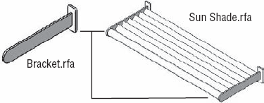
With two clicks of the mouse, you can quickly add rich 3D content to your model. Figure 11.10 shows a sunshade example. (Figure 11.1 showed this same sunshade in 3D.) The brackets at the left and right side were modeled in the family using solid extrusions and constrained to the left and right reference planes. The blades were modeled as sweeps between the two horizontal reference planes, using a profile. When placed in the model, the sunshade can be stretched dynamically.

For elements that need the flexibility to be placed on any model face, such as electrical outlets, signage, or coffee pots, there are work plane and face-based families. Not only do these families attach to any surface of the model during placement, but you can also re-host them at any point later to any other surface if need be. Any time you have a component that needs to be installed on multiple types of hosts, think of making the family face-based.
To create face-based families, use the template Generic Model face based.rft. When you open the template, you'll see an abstract host surface on which you can model your family. When you load your family into your project, the host surface in the family maps to whatever face you choose in the project, and your family reorients to be placed on that face automatically. The face you choose can be anything from another family to geometry of a linked file. An example of a face-based family is an HVAC supply register, which you need to be able to place on walls, ceilings, or even floors. Figure 11.11 shows another application of a face-based component, where the curved surface doesn't have a work plane.

Work plane-based families are placed on the active work plane of the current view. Every view has an active work plane that you can manipulate using the Work Plane tool (see Chapter 6, "Modeling Principles in Revit, Part 1").
Be sure to give the family an appropriate category before loading it so you can control its visibility and graphics.
When you're rendering a view, it's possible to substitute real model geometry (the family) with highly photorealistic images (such as ArchVision content, available at http://www.archvision.com/). For example, a simplified stick figure can turn into a real-looking person when the view is rendered (see Figure 11.12).

This can be a cool feature when you're rendering, and it makes rendering faster because there is no complex geometry to render. You can create plants, cars, and people using these families.
RPC families are specialized and have specific behavior when rendered. In addition to the 3D and 2D representation that you normally add to a family, you can assign a rendering appearance to the family. This appearance shows up only when you render a 3D view.
You create RPC families using the template RPC Family.rft. RPC appearances can only be added to the Entourage and Planting families. When the family is set to either of these categories, a Rendering Type parameter is enabled in the dialog box that opens when you select Category and Parameters from the Create ribbon. RPC families in these categories have additional type parameters (located in the Family Types dialog box; see Figure 11.13) to control the associated RPC file used when the family is rendered in a project, along with specific properties.

Figure 11.14 shows the Render Appearance library and some of the people/characters that come with Revit.
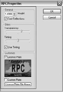
Once you've selected an RPC object, you can further refine the properties of the object by clicking on the first Render Appearance parameter. Figure 11.15 shows the properties of a Steelcase Think chair, with options to change the back and seat fabric. You'll also notice that RPC content supplies you with 3D model geometry.

As you'll see in Chapters 20 and 21 ("Developing the Design with Smart Workflows" and "Moving from Design to Detailed Documentation"), a typical workflow to complete a construction document set involves enriching the model with 2D details in detail views. These detail elements typically depict cross sections or elevation views of elements that don't need to be modeled in full 3D (to do so would only bog down the model and not add much value). For this use case, you can use detail component families to add detail to model or drafting views; these details are visible only in the view in which they're placed. Examples include blocking, studs, steel sections, bolts, flashing, and so on:

Detail components can contain lines, filled regions, masking regions, symbols, and other detail components. Detail components are meant to represent real building components and assemblies, so they scale with the model when the view scale is changed. To create a new detail component family, use Detail Component line based.rft or Detail Component.rft.
To accommodate fast and easy creation of architectural content, many templates have been made for you with the appropriate category selected. Examples include Furniture.rft, Furniture Systems.rft, Mechanical Equipment.rft, and Plumbing fixture.rft, to name a few. Use these templates to make content when starting from scratch.
Curtain walls and aluminum storefront systems are composed of mullions, panels, operable windows, and doorways. In Revit, the Curtain Wall tool organizes all these components into an integrated system of parts. For panels, the default solid and glazed options are usually sufficient. Adding doors and windows to a curtain wall requires you to make custom windows and doors made with a special template in the Family Editor. Figure 11.16 shows a curtain wall door family in the Family Editor. (These templates don't contain host walls as other door family templates do.)
Keep this in mind: to add doors to a curtain wall, you must use one of the special curtain wall doors; you can't place a standard door into a curtain wall. Use the Door - Curtain Wall.rft template to create these families. They resemble regular door families, but the width and height are dynamically tied to the size of the curtain wall cell in which the door is placed. As the curtain grid spacing changes, so does the size of doors placed in the wall. As you can see in Figure 11.17, the door family adapts to the size of the curtain grid spacing.
In every Revit family, settings control specific behavior of the family and set the category. Depending on what category you assign the family, you can get a different set of type parameters and category-based parameters. For example, in a window family template, preset parameters for sill height, width, and height are hard-coded into the family (see Figure 11.18). In a furniture family template, you don't see these parameters.

Another set of parameters affects the entire family based on the category it belongs to. You can access these settings by choosing Category and Parameters on the Create tab. In the resulting dialog box (Figure 11.19), you can set or change the category and also adjust other parameters that affect how the family will behave when placed in a model.

In the figure, the Entourage category has four family parameters listed: Work Plane-Based, Always Vertical, Rendering Appearance Source, and Shared. Remember that changing the active category at the top of the dialog box may enable or remove family parameters displayed in the bottom of this dialog box. Let's briefly review what these parameters do.
- Work Plane-Based.
Enabling this option allows the family to be hosted by the active work plane when placed in the project or nested into another family. Any nonhosted family can be set to be work plane-based. Any family using the generic template (furniture, site, casework, and so on) can be set to work plane-based, as such families aren't required to be hosted by another component (like doors or windows).
- Always Vertical.
This parameter keeps a family oriented in the positive Z direction when placed in a project. In most cases this is desired, because levels are always horizontal. But when you have sloped floors or sloped site conditions, you may want the component to be oriented perpendicular to the surface it's placed upon. Parking stripes and cars placed on a sloped slab of a parking structure are examples where making the family not always vertical can make sense (see Figure 11.20).
As another example, the Always Vertical parameter comes into play with trees placed on a toposurface. As the site changes slope, you want to keep the trees vertical and not have them look like they're falling over.
- Rendering Appearance Source.
This only applies to the categories Planting and Entourage. There are two options here: Third-Party or Family Geometry. Choosing Third-Party automatically imports 3D geometry from RPC content. Choosing Family Geometry does not use RPC geometry but rather the geometry you construct yourself in the Family Editor.
- Shared.
This parameter controls whether or not a nested family will be scheduled in a project of a family that is nested in another family component. You may choose to nest families to create assemblies or save time modeling components that repeat. Nesting has implications when you need to tag or schedule the family. For example, consider a window assembly with a main light and two side lights—one on each side. If the design intent is that the window is to be tagged and scheduled as a unit, then the families will be nested into a host family and the Shared parameter will remain unchecked. In this situation, only the host family (the family containing all nested windows) will schedule. If the intent is that the assembly be constructed from separately purchased units and assembled on site, then the nested families should have the Shared parameter checked. This allows each nested window to appear on the schedule as if placed separately.

When you choose some structural categories, you'll see additional options show up that are specific to structural framing, foundations, and columns. We will not go into detail here on each of these, but structural engineers should be aware that special functionality has been built into family templates depending on the type of family you are creating.
When you open a family in the Family Editor, you can load another family and place instances of it into your host family much as you would in a project. This powerful feature allows you to manage your content and reuse existing work. For example, consider the workstation family illustrated in Figure 11.21.
This family is composed of loaded filing cabinets, a desktop, partitions, and a chair. This makes building the family much more manageable and also makes it much easier to place and manipulate the family as a unit when placed in a project. In this example, you'd want to make sure that the filing cabinets were set not to display in plan views, since they're obscured by the working surface.
One common example of family nesting is the combination window. Rather than model the entire unit from scratch, you can load and insert existing window components into a base window family. You place the windows just as you would in a project. For example, you can place a fixed-window family in the center and two double-hung windows on either side (see Figure 11.22). You can then save the family and load it into a project. The entire assembly acts as one element when placed in the model.


Choosing to use nested families not only saves modeling time but can also simplify your work in the Family Editor. It's often easier to manipulate and constrain an assembly of extrusions as a nested family than to model the same geometry in the host family. In another example, a bracket for a sunshade is modeled separately and nested into the host sunshade family (Figure 11.23). Two instances of the bracket can now be placed and constrained in the family much more easily than modeling the same elements as separate extrusions. Later in the chapter, we review some powerful features that you can use via family nesting.
Finally, nesting of one family in others allows for centralized change management: if you create a handle, you can nest it in doors, windows, or curtain wall doors and windows. If any change is made to the handle, it will propagate to all other families where it has been nested.
When a family is nested in another family, by default it doesn't appear in project schedules and isn't taggable. For the most part, this is the desired behavior because it avoids overburdening your schedules with unneeded subassembly elements. A nested family's geometry displays, but is treated as part of the host family.
In some cases, you may want to schedule nested families—for example, if you've nested chairs within a table family. To expose nested families to tagging and scheduling, you need to enable a parameter called Shared, as we detailed earlier. To do so, follow these steps:
Open the nested family.
Choose Categories and Parameters.
Select the Shared option in the Family Parameters group.
Reload the family into all its host families, and then reload those host families into your project.
Once all your nested families have sharing enabled, they will be schedulable and can also be tagged in your project. Keep in mind that once a family is shared and placed in the project, it's not possible to "unshare" the family and reload it into the model.
When families are nested, the parameters of the nested family aren't visible in your project by default. Only the parameters of the host family are visible, and they can be modified in the project environment. If the element you're nesting is unlikely to change parametrically, this may be desirable. However, if you want to control the nested element's parameters as well, you must explicitly link them to parameters in the host family.
In our example, the support bracket of the sunshade is a nested family, and you need to be able to drive its dimension from the context of the project.
In Figure 11.24, the depth of the nested bracket family is associated with the depth of the host Sun Shade family. Changing the Depth parameter of the sunshade causes the depth of all support brackets to also change to the same value.
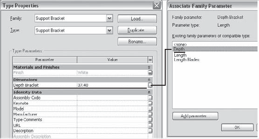
You can link any kind of parameter, from dimensions to materials to text. For example, the Sun Shade family has two material parameters: Material Supports and Material Blades. By selecting one of the nested brackets and opening its type properties, you can assign its Finish Material parameter to the sunshade (host) material parameter Material Supports. When this is done, you can control the bracket material from the project by assigning a material to the sunshade's Material Supports property.
Parameters in many nested families can be linked to a single parameter in a host family to provide powerful control over size, quantity, and even display of family subassemblies from within a project. This is a great way to limit exposing a family's internal complexity when the family is loaded into a project.
Every nested family or piece of solid geometry has a Visible parameter. This parameter allows you to control the visibility of nested families by creating a Yes/No parameter in the host family and then linking the nested family to that parameter. Checking or clearing this check box controls the element's visibility in the host family when viewed in a project. Keep in mind the Visibility option only controls visibility! If the nested element is shared, it will still schedule.
For example, let's look at a window family that has a shutter family nested in it and two instances placed on either side of the window. You can create a Yes/No parameter called DisplayShutters in the window family and link the Visible parameter of the shutter family to this parameter (Figure 11.25).

Figure 11.25. Linking a Yes/No parameter to the Visible parameter allows the same window to be shown with and without shutters.
Two types are then created: Window w Shutters and Window w/o Shutters. The former has DisplayShutters selected and the latter has it deselected. When they are loaded into the project, you can use the two types to control whether or not the shutters are visible (Figure 11.26).

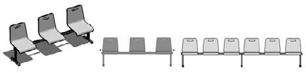
There are many examples of building components that have repetitive subcomponents built into them: evenly spaced shelves, brackets, structural members, nested chairs, or other components—the list goes on. Figure 11.27 shows a perfect example where using an array to place vertical and horizontal shelves makes sense.

Figure 11.27. Arrays can help maintain element spacing in a family and allow you to control the number of grouped element instances.
To make a parametric array in the Family Editor, you need to use the Group and Associate option in the Options bar. This allows you to parameterize the number of instances of the element in the array. When you select the array, a number appears that corresponds to the total number of groups in the array. If you change this number, the number of groups in the array updates. If the array was created with the option Move to: Last, elements are added or removed between the start and end of the array as defined when it was created. If the array was created with the option Move to: 2nd, elements are added or removed after the end of the array.
You can turn the array number into a parameter by selecting the array and labeling it as a parameter (see Figure 11.28). Once the number is selected, the Options bar displays a Label drop-down menu. Select <Add Parameter...> to create a new number parameter.
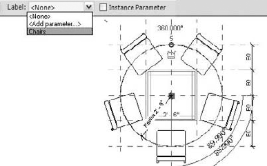
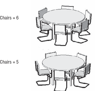
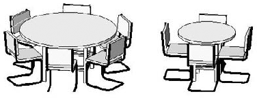
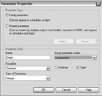
Once you make the assignment of the array number to a type parameter, the number of elements in the array can be controlled from the Family Types dialog box. In Figure 11.29, the number parameter Chairs controls the number of chairs in the radial array. Changing the number automatically changes the number of elements in the array.
Proportion has been an important consideration in the design of objects for centuries. Relating width, height, and depth to a design rule informed the design of architecture dating back to early Greek and Egyptian times. The dimensional size of one element often drives the size of other related elements. Think, for example, of a window with muntins; the number of muntins often grows in proportion to the size of the window (see Figure 11.30). To this end, Revit provides ways to relate parameters to one another using formulas. By changing one dimension of a component, you can effectively change many other dimensions and thereby maintain design intent. Often, your family will have parameters that determine its dimensions, and it's the relationship between these dimensions that you want to maintain.
In a simple case, you can imagine using a formula to set the width of a shutter in a window family. The window family may already have types that control its width and height. Knowing that the shutters should always be equal to the window height and half the width, you can use a formula and let Revit do the calculation for you. Follow these steps:
Load the shutter family into your window family, and place an instance on either side of the window.
In the window Family Types dialog box, create a new parameter by clicking the Add button:

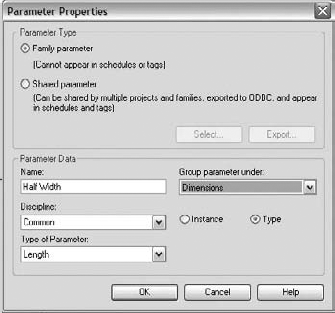
In the Parameter Properties dialog box (see Figure 11.31), give the parameter the name Half Width, and set Type of Parameter to Length. You can group the parameter under Dimensions to make it easier to find.
Back in the Family Types dialog box, in the parameter's formula field, enter =Width / 2 (see Figure 11.32). This ensures that the parameter is always half the window's width. The Value field displays the calculated value; when the family is loaded into your project, the parameter will display but won't be editable.
Select the nested shutter in your family, and link its dimensions to the window so they change together. To do so, in the Associate Parameter dialog box (accessed from the small button at the far right of the parameter row), click the button in the correct row of the Shutter element properties. Associating the shutter's Width parameter with the window's Half Width parameter and its Height to the window's Height connects the two objects.
The shutter will now adapt its dimensions to the window whenever its shape is adjusted.

In the next example, you'll see how you can use a formula to control the number of elements in an array used to construct a sun-shading family (Figure 11.33). (You'll find this file, Sunshade.rfa, on the book's companion web page, www.sybex.com/go/masteringrevit2010.)

This family is constructed of a support bracket and blades that make up the shade. The design calls for supports to be added dynamically as a function of length. In this example, both the brackets and the shades are arrayed so that their quantity is determined by the size of the family when placed in the project. The number of brackets is controlled by the Support Quantity parameter, and the number of blades in the shade is controlled by Blade Quantity. Both of these can be driven by formulas. The calculated value of a formula is always displayed in the Value column. Let's look deeper at this design problem and see how it can be solved.
Support Quantity uses a conditional statement to guarantee that there are always at least two support brackets in the family. A conditional statement takes this general form:
If (condition, do this, else do this)
In the support case, if Support Minimum is true, then the number of supports is set to Length / 60. If it's false, then the value is 2.
Support Minimum is a Yes/No parameter that's also set to a formula. In this case, if Length (the length of the family) is greater than 135″, Support Minimum is Yes (true); otherwise, it's No (false).
In Figure 11.34, you see the default Length value is 110″. So Support Minimum is false, and Support Quantity is set to 2. When the length exceeds 180″, Support Quantity equals 3, and an additional support bracket is introduced via the array.

Blade Quantity is simpler. The conditional statement determines whether the depth is greater than 15.75″. When the depth is larger (shown as 37″), the number of blades is one more than Depth – 10″ / 6. When the depth is less than 15.75″, there are only two blades.
Figure 11.35 shows how changing the length to 180″ causes a new bracket to be added based on the formula.
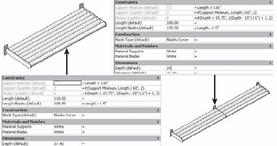
Figure 11.35. Different shade sizes evaluated via the formula. On the left, two supports are added. On the right, three supports are added.
We constructed an advanced line-based family to model an exterior shading element. The family uses arrays with a formula to capture the design intent regarding the number of blades, proper support spacing, and blade angle. The resulting family can be quickly placed with two clicks, and the correct number of supports are placed. Note that the way this family is constructed, it must be placed in a plan view of the model. Once you place the family, you can experiment with different blade angles and numbers of blades in the system by changing a few properties:
In this exercise, you'll assemble a furniture ensemble consisting of a round table surrounded by chairs (see Figure 11.36). To accomplish this, you'll do the following:
To nest a chair into the table family so the whole family works as a unit, follow these steps:
Open
Table Round.rfafrom the Chapter 11 folder of the book's companion web page (www.sybex.com/go/masteringrevit2010).Open the Ref. Level plan view using the Project Browser, and fit the view to the screen.
Choose Load Family from the Insert ribbon and load
Chair-Breuer.rfafrom the Chapter 11 folder.Activate the Component tool on the Create ribbon. The active component in the Type Selector should be Chair-Breuer.
Place a single instance of the chair, as shown in Figure 11.37. Use the spacebar to rotate the chair to face the table, and type SI to use the intersection snap override to snap the chair origin to the reference-plane intersection.

Next, you'll make the chair array become parametrically driven. Follow these steps:
Click the Types command on the Create ribbon to launch the Family Types dialog box.
In the Parameters group, click Add.
In the Parameter Properties dialog box, enter the information shown in Figure 11.38 for the parameter, and click OK.
Add a Radius parameter (Figure 11.39), and click OK.
For the Radius parameter, enter the following in the Formula column: Diameter / 2. This ensures that the radius is half the diameter.
For the Chairs parameter, enter the following in the Formula column:
(Diameter *3.14)/2′6″ This formula sets the desired number of chairs relative to the circumference of the table.
Select the chair instance you placed earlier, and select the Array tool. Change the array type in the Options bar from linear to radial. A red box appears around the chair, with a blue rotate control in the center. Drag the blue control to the intersection of the two reference planes at the center of the table to set the center of the array.
Define the start of the array by clicking at the origin of the chair, and then move your mouse into the Options bar area. Set the Move To radio button to Last, and enter 360 in the Angle field.
Press the Enter key twice. Revit creates three chairs.
To constrain the array to the radius of the table, activate the Dimension tool, and choose the Radial placement method from the Options bar:
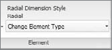
Hold the tool over the table edge, and press Tab until the status bar reads Array : Array. Click in any whitespace to finish the dimension.

Select the dimension. In the Options bar, set the Label drop-down menu to the Radius parameter. This sets the radius of the array to match the radius of the table.
Select a chair group, and then the array reference (the line that connects the chair groups and displays the array number). You may need to press Tab until you see the status bar read Array: Array.
Once you make this selection, the number of chairs should change to match the value of the formula-driven Chairs parameter (Figure 11.40).


To modify the family so that chairs can be made visible (or not visible) as part of the family definition, follow these steps:
Click Types on the Create tab to open the Family Types dialog box.
In the Parameters group, click Add.
In the Parameter Properties dialog box, enter the data shown in Figure 11.41.
Click OK.
Select one of the chair groups, and choose Edit Group from the Group panel.
Select the chair, and edit its element properties, either by right-clicking and using the context menu or by clicking the Element Properties from the Element panel.
Under the Graphics group, find the Visible parameter. At the far right end of the row, click the small button to launch the Associate Family Parameter dialog box.
In the dialog box, choose the displaysChairs parameter you created earlier.
Click OK twice to dismiss the Associate Family Parameter and Element Properties dialog boxes; then, click Finish Group.
Click the Types command to launch the Family Types dialog box.
Choose the type 36″ Diameter in the Type drop-down list at the top of the dialog box.
At the right, in the Family Types group, choose New.
Type in the name 36″ Diameter no Chairs, and then click OK.
In the Graphics group, select the displaysChairs parameter, and then Click OK to close the Family Types dialog box.
Save the family. Choose Load into Project from the Create ribbon to view the completed family.
You should have four types of families available. Place an instance of each to see the results (see Figure 11.42).


- Model parametric 3D families.
When you're making a new family, consider how it will be used in the model, and choose an appropriate template.
- Master It
You found a ceiling-mounted lighting fixture that you want to use in your existing project, but you can't find a Revit family for it in any libraries or online communities. How would you start?
- Nest one family into another.
The ability to nest families in other families lets you create content that's easier to manage and improves your workflow.
- Master It
Building components are often composed of a series of subcomponents that form an overall assembly. Think of some common examples and what strategies you could use to build such content in Revit.
- Build relationships between parameters with formulas.
Create smart connections between geometry and dimensions to create efficient and parametric content.
- Master It
You can use dimensional relationships to tie the size of one object to the size of another. How do you do this in the context of a family?