

i
i
i
i
i
i
i
i
16 2. The Graphics Rendering Pipeline
Projection
Clipping
Model & View
Transform
Vertex
Shading
Screen
Mapping
Figure 2.3. The geometry stage subdivided into a pipeline of functional stages.
For example, at one extreme, all stages in the entire rendering pipeline
may run in software on a single processor, and then you could say that your
entire pipeline consists of one pipeline stage. Certainly this was how all
graphics were generated before the advent of separate accelerator chips and
boards. At the other extreme, each functional stage could be subdivided
into several smaller pipeline stages, and each such pipeline stage could
execute on a designated processor core element.
2.3.1 Model and View Transform
On its way to the screen, a model is transformed into several different spaces
or coordinate systems. Originally, a model resides in its own model space,
which simply means that it has not been transformed at all. Each model
can be associated with a model transform so that it can be positioned and
oriented. It is possible to have several model transforms associated with
a single model. This allows several copies (called instances)ofthesame
model to have different locations, orientations, and sizes in the same scene,
without requiring replication of the basic geometry.
It is the vertices and the normals of the model that are transformed by
the model transform. The coordinates of an object are called model coordi-
nates, and after the model transform has been applied to these coordinates,
the model is said to be located in world coordinates or in world space.The
world space is unique, and after the models have been transformed with
their respective model transforms, all models exist in this same space.
As mentioned previously, only the models that the camera (or observer)
sees are rendered. The camera has a location in world space and a direction,
which are used to place and aim the camera. To facilitate projection and
clipping, the camera and all the models are transformed with the view
transform. The purpose of the view transform is to place the camera at
the origin and aim it, to make it look in the direction of the negative z-axis,
2
with the y-axis pointing upwards and the x-axispointingtotheright. The
actual position and direction after the view transform has been applied are
dependent on the underlying application programming interface (API). The
2
We will be using the −z-axis convention; some texts prefer looking down the +z-axis.
The difference is mostly semantic, as transform between one and the other is simple.

i
i
i
i
i
i
i
i
2.3. The Geometry Stage 17
Figure 2.4. In the left illustration, the camera is located and oriented as the user wants
it to be. The view transform relocates the camera at the origin, looking along the
negative z-axis, as shown on the right. This is done to make the clipping and projection
operations simpler and faster. The light gray area is the view volume. Here, perspective
viewing is assumed, since the view volume is a frustum. Similar techniques apply to any
kind of projection.
space thus delineated is called the camera space, or more commonly, the
eye space. An example of the way in which the view transform affects the
camera and the models is shown in Figure 2.4. Both the model transform
and the view transform are implemented as 4 × 4 matrices, which is the
topic of Chapter 4.
2.3.2 Vertex Shading
To produce a realistic scene, it is not sufficient to render the shape and
position of objects, but their appearance must be modeled as well. This
description includes each object’s material, as well as the effect of any light
sources shining on the object. Materials and lights can be modeled in any
number of ways, from simple colors to elaborate representations of physical
descriptions.
This operation of determining the effect of a light on a material is known
as shading. It involves computing a shading equation at various points on
the object. Typically, some of these computations are performed during
the geometry stage on a model’s vertices, and others may be performed
during per-pixel rasterization. A variety of material data can be stored at
each vertex, such as the point’s location, a normal, a color, or any other
numerical information that is needed to compute the shading equation.
Vertex shading results (which can be colors, vectors, texture coordinates,
or any other kind of shading data) are then sent to the rasterization stage
to be interpolated.
Shading computations are usually considered as happening in world
space. In practice, it is sometimes convenient to transform the relevant
entities (such as the camera and light sources) to some other space (such

i
i
i
i
i
i
i
i
18 2. The Graphics Rendering Pipeline
as model or eye space) and perform the computations there. This works
because the relative relationships between light sources, the camera, and
the models are preserved if all entities that are included in the shading
calculations are transformed to the same space.
Shading is discussed in more depth throughout this book, most specif-
ically in Chapters 3 and 5.
2.3.3 Projection
After shading, rendering systems perform projection, which transforms the
view volume into a unit cube with its extreme points at (−1, −1, −1) and
(1, 1, 1).
3
The unit cube is called the canonical view volume.Thereare
two commonly used projection methods, namely orthographic (also called
parallel)
4
and perspective projection. See Figure 2.5.
Figure 2.5. On the left is an orthographic, or parallel, projection; on the right is a
perspective projection.
3
Different volumes can be used, for example 0 ≤ z ≤ 1. Blinn has an interesting
article [102] on using other intervals.
4
Actually, orthographic is just one type of parallel projection. For example, there is
also an oblique parallel projection method [516], which is much less commonly used.
i
i
i
i
i
i
i
i
2.3. The Geometry Stage 19
The view volume of orthographic viewing is normally a rectangular
box, and the orthographic projection transforms this view volume into
the unit cube. The main characteristic of orthographic projection is that
parallel lines remain parallel after the transform. This transformation is a
combination of a translation and a scaling.
The perspective projection is a bit more complex. In this type of projec-
tion, the farther away an object lies from the camera, the smaller it appears
after projection. In addition, parallel lines may converge at the horizon.
The perspective transform thus mimics the way we perceive objects’ size.
Geometrically, the view volume, called a frustum, is a truncated pyramid
with rectangular base. The frustum is transformed into the unit cube as
well. Both orthographic and perspective transforms can be constructed
with 4 ×4 matrices (see Chapter 4), and after either transform, the models
are said to be in normalized device coordinates.
Although these matrices transform one volume into another, they are
called projections because after display, the z-coordinate is not stored in
the image generated.
5
In this way, the models are projected from three to
two dimensions.
2.3.4 Clipping
Only the primitives wholly or partially inside the view volume need to be
passed on to the rasterizer stage, which then draws them on the screen. A
primitive that lies totally inside the view volume will be passed on to the
next stage as is. Primitives entirely outside the view volume are not passed
on further, since they are not rendered. It is the primitives that are par-
tially inside the view volume that require clipping. For example, a line that
has one vertex outside and one inside the view volume should be clipped
against the view volume, so that the vertex that is outside is replaced by
a new vertex that is located at the intersection between the line and the
view volume. The use of a projection matrix means that the transformed
primitives are clipped against the unit cube. The advantage of performing
the view transformation and projection before clipping is that it makes the
clipping problem consistent; primitives are always clipped against the unit
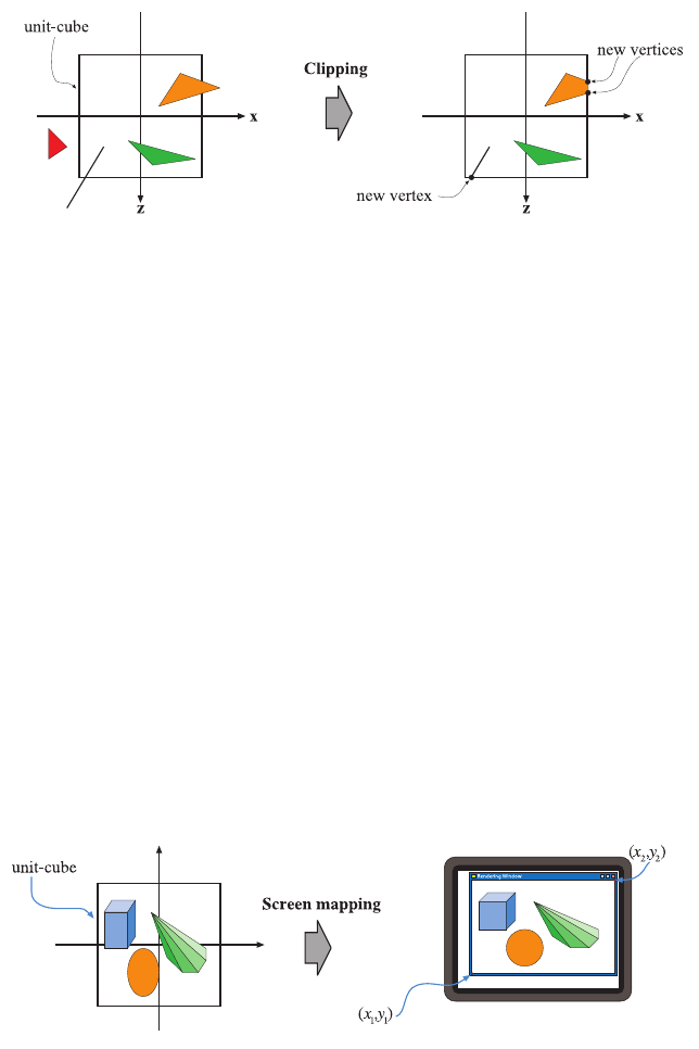
cube. The clipping process is depicted in Figure 2.6. In addition to the six
clipping planes of the view volume, the user can define additional clipping
planes to visibly chop objects. An image showing this type of visualization,
called sectioning, is shown in Figure 14.1 on page 646. Unlike the previous
geometry stages, which are typically performed by programmable process-
ing units, the clipping stage (as well as the subsequent screen mapping
stage) is usually processed by fixed-operation hardware.
5
Rather, the z-coordinate is stored in a Z-buffer. See Section 2.4.
i
i
i
i
i
i
i
i
20 2. The Graphics Rendering Pipeline
Figure 2.6. After the projection transform, only the primitives inside the unit cube (which
correspond to primitives inside the view frustum) are needed for continued processing.
Therefore, the primitives outside the unit cube are discarded and primitives totally inside
are kept. Primitives intersecting with the unit cube are clipped against the unit cube,
and thus new vertices are generated and old ones are discarded.
2.3.5 Screen Mapping
Only the (clipped) primitives inside the view volume are passed on to the
screen mapping stage, and the coordinates are still three dimensional when
entering this stage. The x-andy-coordinates of each primitive are trans-
formed to form screen coordinates. Screen coordinates together with the
z-coordinates are also called window coordinates. Assume that the scene
should be rendered into a window with the minimum corner at (x
1
,y
1
)and
the maximum corner at (x
2
,y
2
), where x
1
<x
2
and y
1
<y
2
. Then the
screen mapping is a translation followed by a scaling operation. The z-
coordinate is not affected by this mapping. The new x-andy-coordinates
are said to be screen coordinates. These, along with the z-coordinate
(−1 ≤ z ≤ 1), are passed on to the rasterizer stage. The screen map-
ping process is depicted in Figure 2.7.
A source of confusion is how integer and floating point values relate
to pixel (and texture) coordinates. DirectX 9 and its predecessors use a
Figure 2.7. The primitives lie in the unit cube after the projection transform, and the
screen mapping procedure takes care of finding the coordinates on the screen.
..................Content has been hidden....................
You can't read the all page of ebook, please click here login for view all page.