
i
i
i
i
i
i
i
i
5.7. Transparency, Alpha, and Compositing 139
combine to cover only 75% of the pixel, allowing 25% of the background to
show through. This sort of error is avoided by using coverage masks or by
blurring the edges outwards, as discussed in the previous section.
To summarize, the alpha value can represent transparency, edge cover-
age, or both (if one multiplies the two alphas together).
E
XAMPLE:BLENDING. A teapot is rendered onto a background using anti-
aliasing techniques. Say that at some pixel the shade of the surface is a
beige, (0.8, 0.7, 0.1), the background is a light blue, (0.7, 0.7, 0.9), and the
surface is found to cover 0.6 of the pixel. The blend of these two colors is
0.6(0.8, 0.7, 0.1) + (1 − 0.6)(0.7, 0.7, 0.9),
which gives a color of (0.76, 0.7, 0.42).
The over operator turns out to be useful for blending together pho-
tographs or synthetic renderings of objects. This process is called com-
positing [143, 1197]. In such cases, the alpha value at each pixel is stored
along with the RGB color value for the object. The alpha channel is some-
times called the matte and shows the silhouette shape of the object. See
Figure 6.24 on page 182 for an example. This RGBα image can then be
used to blend it with other such elements or against a background.
There are a number of other blending operators besides over [143, 1026],
but most are not as commonly used in real-time applications. One excep-
tion is additive blending, where pixel values are simply summed. That is,
c
o
= α
s
c
s
+ c
d
. (5.18)
This blending mode has the advantage of not requiring sorting between
triangles, since addition can be done in any order. It can work well for
glowing effects that do not attenuate the pixels behind them but only
brighten them. However, this mode does not look correct for transparency,
as the opaque surfaces do not appear filtered [849]. For a number of layered
semitransparent surfaces, such as smoke or fire, additive blending has the
effect of saturating the colors of the phenomenon [928].
The most common way to store synthetic RGBα imagesiswithpremul-
tiplied alphas (also known as associated alphas). That is, the RGB values
are multiplied by the alpha value before being stored. This makes the
compositing over equation more efficient:
c
o
= c
s
+(1− α
s
)c
d
, (5.19)
where c
s
is the premultiplied source channel. Also important, premultiplied
alphas allow cleaner theoretical treatment [1197]. Note that with premul-
tiplied RGBα values, the RGB components are normally not greater than
the alpha value.
i
i
i
i
i
i
i
i
140 5. Visual Appearance
Rendering synthetic images meshes naturally with premultiplied alphas.
An antialiased opaque object rendered over a black background provides
premultiplied values by default. Say a white (1, 1, 1) polygon covers 40% of
some pixel along its edge. With (extremely precise) antialiasing, the pixel
value would be set to a gray of 0.4—we would save the color (0.4, 0.4, 0.4)
for this pixel. The alpha value, if stored, would also be 0.4, since this is the
area the polygon covered. The RGBA value would be (0.4, 0.4, 0.4, 0.4),
which is a premultiplied value.
Another way images are stored is with unmultiplied alphas,alsoknown
as unassociated alphas (or even as the mind-bending term nonpremultiplied
alphas). An unmultiplied alpha is just what it says: The RGB value is
not multiplied by the alpha value. This is rarely used in synthetic image
storage, since the final color we see at a pixel is not the shade of the polygon;
it is the shade multiplied by alpha, blended with the background. For
the white polygon example, the unmultiplied color would be (1, 1, 1, 0.4).
This representation has the advantage of storing the polygon’s original
color, but this color would always need to be multiplied by the stored
alpha to be displayed correctly. It is normally best to use premultiplied
whenever filtering and blending is performed, as operations such as linear
interpolation do not work correctly using unmultiplied alphas [67, 104].
For image-manipulation applications, an unassociated alpha is useful to
mask a photograph without affecting the underlying image’s original data.
Image file formats that support alpha include TIFF (both types of alpha)
and PNG (unassociated alpha only) [912].
A concept related to the alpha channel is chroma-keying [143]. This is a
term from video production, in which actors are filmed against a blue, yel-
low, or (increasingly common) green screen and blended with a background.
In the film industry this process is called green-screen or blue-screen mat-
ting. The idea here is that a particular color is designated to be considered
transparent; where it is detected, the background is displayed. This allows
images to be given an outline shape by using just RGB colors—no alpha
needs to be stored. One drawback of this scheme is that the object is either
entirely opaque or transparent at any pixel, i.e., alpha is effectively only
1.0or0.0. As an example, the GIF format allows one color (actually, one
palette entry; see Section 18.1.1) to be designated as transparent.
The over operator can be used for rendering semitransparent objects
on top of whatever has been rendered before, e.g., opaque objects and
more distant transparent objects. This works, in the sense that we perceive
something as transparent whenever the objects behind can be seen through
it [554]. But the over operator is more correctly used to represent some
approximation of how much an opaque object covers a pixel’s cell. A more
representative formula for how a transparent object acts is to represent it
by a combination of filtering and reflection. To filter, the scene behind the
i
i
i
i
i
i
i
i
5.8. Gamma Correction 141
transparent object should be multiplied by the transparent object’s spectral
opacity [1348]. For example, a yellow piece of stained glass multiplies the
scene’s color by its RGB yellow color. The stained glass itself might reflect
some light toward the eye, a contribution that should then be added in.
To simulate this with alpha blending, we would need to multiply the frame
buffer by one RGB color and then add another RGB color. Doing this in
a single pass cannot be done with regular alpha blending, but is possible
with dual-color blending, added in DirectX 10 (see Section 3.7). Physically
correct transparency is discussed in Sections 7.5.3, 9.4, and 9.5.
One last note on alpha: This channel can be used to store whatever
you like. For image file formats, the stored alpha usually has a specific
meaning, either unmultiplied or premultiplied. During shader computa-
tions, however, the alpha channel is sometimes a convenient place to store
a grayscale specular contribution, power, or other scaling factor. An un-
derstanding of the available blending modes can make a variety of effects
rapid to compute.
5.8 Gamma Correction
Once the pixel values have been computed, we need to display them on
a monitor. In the early years of digital imaging, cathode-ray tube (CRT)
monitors were almost exclusively used. CRT monitors exhibit a power law
relationship between input voltage and display radiance, which turns out to
nearly match the inverse of light sensitivity of the human eye [1028]. The
consequence of this fortunate coincidence is that an encoding proportional
to CRT input voltage is roughly perceptually uniform (the perceptual differ-
ence between a pair of encoded values N and N +1 is roughly constant over
the displayable range). This near-optimal distribution of values minimizes
banding artifacts, which can be particularly bothersome when the number
of distinct values is small (as is the case with color buffers storing 8 bits or
less per channel). Now that CRT displays are rare, perceptual uniformity
is one reason for using power-law encodings. The desire for compatibility
with existing images is another important factor. LCDs have different tone
response curves than CRTs, but hardware adjustments are usually made
to provide compatibility [329, 1157].
The transfer functions that define the relationship between radiance
12
and encoded pixel values are slightly modified power curves. It is custom-
ary to characterize such a function by the power curve that most closely
12
Actually, a normalized radiance value that ranges from 0 (for display black level)to
1 (for maximum display radiance).

i
i
i
i
i
i
i
i
142 5. Visual Appearance
display transfer function
display radiance
display radiance
scene radiance scene radiance
encoded pixel values
encoded pixel values
encoding transfer function end-to-end transfer functio
n
Figure 5.38. On the left is the function relating normalized scene radiance to encoded
pixel values. In the middle is the function relating encoded pixel values to normalized
display radiance. The concatenation of the two functions gives the end-to-end transfer
function of the imaging system, shown to the right.
approximates it in the 0 to 1 range:
f
xfer
(x) ≈ x
γ
, (5.20)
or more precisely, by the exponent γ (gamma) of this curve.
Two gamma values are needed to fully characterize an imaging sys-
tem. The encoding gamma describes the encoding transfer function,which
is the relationship between scene radiance values captured by an imaging
device (such as a camera) and encoded pixel values. The display gamma
characterizes the display transfer function, which is the relationship be-
tween encoded pixel values and displayed radiance. The product of the
two gamma values is the overall or end-to-end gamma of the imaging sys-
tem, which describes the end-to-end transfer function (see Figure 5.38). If
this product were equal to 1, then displayed radiance would be propor-
tional to captured scene radiance. This might seem ideal, and it would be
if the display could exactly reproduce the viewing conditions of the original
scene. However, in practice there are two significant differences between
the viewing conditions of the original scene and the displayed version. The
first difference is that absolute display radiance values are several orders of
magnitude less than the scene radiance values (due to limitations in dis-
play device technology). The second difference, called the surround effect ,
refers to the fact that the original scene radiance values fill the entire field
of view of the observer, while the display radiance values are limited to a
screen surrounded by ambient room illumination. This illumination may
be very dark (as in a movie theater), dim (as in the average television-
watching environment) or bright (as in an office). These two differences in
viewing conditions cause the perceived contrast to be dramatically reduced
compared to the original scene. To counteract this, non-unit end-to-end
i
i
i
i
i
i
i
i
5.8. Gamma Correction 143
gamma is used (the recommended value varies from 1.5 for a dark movie
theater to 1.125 for a bright office [1028]), to ensure that the display is
perceptually similar to the original scene.
The relevant gamma for rendering purposes is encoding gamma. Rec.
709 for HDTV uses an encoding gamma of about 0.5 [1028], which is ap-
propriate for applications using television displays. Personal computers
use a standard called sRGB [1223], which has an encoding gamma of about
0.45.
13
This gamma is intended for bright office environments. These en-
coding gamma values are designed to work with a display gamma of 2.5
to produce the appropriate end-to-end gamma. This display gamma is
typical of CRT monitors—newer displays include built-in adjustments to
match CRT display gamma for compatibility.
14
EXAMPLE:GAMMA CORRECTION. A relative color of (0.3, 0.5, 0.6) is com-
puted for a pixel. To display it correctly, each value is raised to a power of
0.45 (1/2.22), giving (0.582, 0.732, 0.794). For a display with eight bits per
channel, these values are multiplied by 255 to give (148, 187, 203), which is
stored in the frame buffer.
It is the responsibility of the renderer to convert physical radiance val-
ues (computed in the shader) into nonlinear frame buffer values by ap-
plying the appropriate transfer function. In the past this was commonly
neglected, leading to various visual artifacts [107, 459]. The main problem
with neglecting this gamma correction is that shading computations that
are correct for physically linear radiance values are performed on nonlinear
values instead. An example of this can be seen in Figure 5.39.
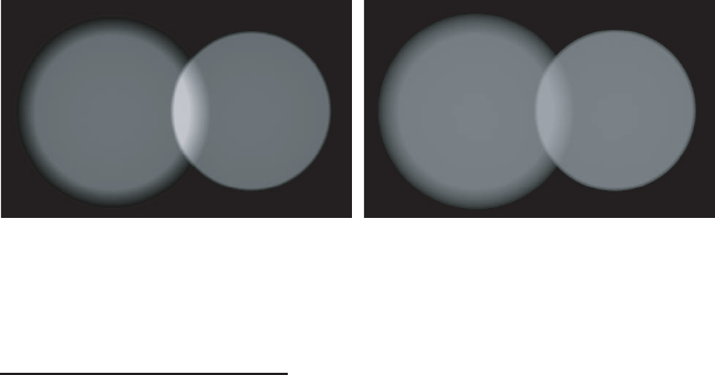
Figure 5.39. Two overlapping spotlights illuminating a plane. In the left image, the
light values have been combined in a nonlinear space (i.e., gamma correction was not
performed). In the right image, proper gamma correction has resulted in the light values
being combined in linear space. Note the overbrightening of the overlap region in the
left image; the right image is correct.
13
Apple Macintosh computers use an encoding gamma of about 0.55 [1028].
14
At least they do if properly calibrated, which unfortunately is often not the case.
..................Content has been hidden....................
You can't read the all page of ebook, please click here login for view all page.