
i
i
i
i
i
i
i
i
3.4. The Vertex Shader 39
this object’s triangles (or lines or points) by essentially creating vertices
with positions and colors. A second object could use the same array of
positions (along with a different model transform matrix) and a different
array of colors for its representation. Data representation is discussed in
detail in Section 12.4.5. There is also support in the input assembler to
perform instancing. This allows an object to be drawn a number of times
with some varying data per instance, all with a single draw call. The use
of instancing is covered in Section 15.4.2. The input assembler in DirectX
10 also tags each instance, primitive, and vertex with an identifier number
that can be accessed by any of the shader stages that follow. For earlier
shader models, such data has to be added explicitly to the model.
A triangle mesh is represented by a set of vertices and additional infor-
mation describing which vertices form each triangle. The vertex shader is
the first stage to process the triangle mesh. The data describing what tri-
angles are formed is unavailable to the vertex shader; as its name implies,
it deals exclusively with the incoming vertices. In general terms, the vertex
shader provides a way to modify, create, or ignore values associated with
each polygon’s vertex, such as its color, normal, texture coordinates, and
position. Normally the vertex shader program transforms vertices from
model space to homogeneous clip space; at a minimum, a vertex shader
must always output this location.
This functionality was first introduced in 2001 with DirectX 8. Because
it was the first stage on the pipeline and invoked relatively infrequently, it
could be implemented on either the GPU or the CPU, which would then
send on the results to the GPU for rasterization. Doing so made the tran-
sition from older to newer hardware a matter of speed, not functionality.
All GPUs currently produced support vertex shading.
A vertex shader itself is very much the same as the common core virtual
machine described earlier in Section 3.2. Every vertex passed in is processed
by the vertex shader program, which then outputs a number of values that
are interpolated across a triangle or line.
3
The vertex shader can neither
create nor destroy vertices, and results generated by one vertex cannot be
passed on to another vertex. Since each vertex is treated independently,
any number of shader processors on the GPU can be applied in parallel to
the incoming stream of vertices.
Chapters that follow explain a number of vertex shader effects, such as
shadow volume creation, vertex blending for animating joints, and silhou-
ette rendering. Other uses for the vertex shader include:
• Lens effects, so that the screen appears fish-eyed, underwater, or
otherwise distorted.
3
Older shader models also supported output of the size of a point sprite particle
object, but sprite functionality is now part of the geometry shader.

i
i
i
i
i
i
i
i
40 3. The Graphics Processing Unit
Figure 3.5. On the left, a normal teapot. A simple shear operation performed by
a vertex shader program produces the middle image. On the right, a noise function
creates a field that distorts the model. (Images produced by FX Composer 2, courtesy
of NVIDIA Corporation.)
• Object definition, by creating a mesh only once and having it be
deformed by the vertex shader.
• Object twist, bend, and taper operations.
• Procedural deformations, such as the movement of flags, cloth, or
water [592].
• Primitive creation, by sending degenerate meshes down the pipeline
and having these be given an area as needed. This functionality is
replaced by the geometry shader in newer GPUs.
• Page curls, heat haze, water ripples, and other effects can be done
by using the entire frame buffer’s contents as a texture on a screen-
aligned mesh undergoing procedural deformation.
• Vertex texture fetch (available in SM 3.0 on up) can be used to apply
textures to vertex meshes, allowing ocean surfaces and terrain height
fields to be applied inexpensively [23, 703, 887].
Some deformations done using a vertex shader are shown in Figure 3.5.
The output of the vertex shader can be consumed in a number of dif-
ferent ways. The usual path is for each instance’s triangles to then be
generated and rasterized, and the individual pixel fragments produced sent
to the pixel shader program for continued processing. With the introduc-
tion of Shader Model 4.0, the data can also be sent to the geometry shader,
streamed out, or both. These options are the subject of the next section.
3.5 The Geometry Shader
The geometry shader was added to the hardware-accelerated graphics pipe-
line with the release of DirectX 10, in late 2006. It is located immediately

i
i
i
i
i
i
i
i
3.5. The Geometry Shader 41
after the vertex shader in the pipeline, and its use is optional. While a
required part of Shader Model 4.0, it is not used in earlier shader models.
The input to the geometry shader is a single object and its associated
vertices. The object is typically a triangle in a mesh, a line segment,
or simply a point. In addition, extended primitives can be defined and
processed by the geometry shader. In particular, three additional vertices
outside of a triangle can be passed in, and the two adjacent vertices on a
polyline can be used. See Figure 3.6.
The geometry shader processes this primitive and outputs zero or more
primitives. Output is in the form of points, polylines, and triangle strips.
More than one triangle strip, for example, can be output by a single invo-
cation of the geometry shader program. As important, no output at all can
be generated by the geometry shader. In this way, a mesh can be selectively
modified by editing vertices, adding new primitives, and removing others.
The geometry shader program is set to input one type of object and
output one type of object, and these types do not have to match. For
example, triangles could be input and their centroids be output as points,
one per triangle input. Even if input and output object types match, the
data carried at each vertex can be omitted or expanded. As an example,
the triangle’s plane normal could be computed and added to each output
vertex’s data. Similar to the vertex shader, the geometry shader must
output a homogeneous clip space location for each vertex produced.
The geometry shader is guaranteed to output results from primitives
in the same order as they are input. This affects performance, because
if a number of shader units run in parallel, results must be saved and
ordered. As a compromise between capability and efficiency, there is a limit
in Shader Model 4.0 of a total of 1024 32-bit values that can be generated
per execution. So, generating a thousand bush leaves given a single leaf
as input is not feasible and is not the recommended use of the geometry
shader. Tessellation of simple surfaces into more elaborate triangle meshes
is also not recommended [123]. This stage is more about programmatically
modifying incoming data or making a limited number of copies, not about
Figure 3.6. Geometry shader input for a geometry shader program is of some single
type: point, line segment, triangle. The two rightmost primitives, which include vertices
adjacent to the line and triangle objects, can also be used.
i
i
i
i
i
i
i
i
42 3. The Graphics Processing Unit
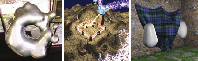
Figure 3.7. Some uses of the geometry shader. On the left, metaball isosurface tessel-
lation is performed on the fly using the GS. In the middle, fractal subdivision of line
segments is done using the GS and stream out, and billboards are generated by the GS
for display. On the right, cloth simulation is performed by using the vertex and geome-
try shader with stream out. (Images from NVIDIA SDK 10 [945] samples courtesy of
NVIDIA Corporation.)
massively replicating or amplifying it. For example, one use is to generate
six transformed copies of data in order to simultaneously render the six
faces of a cube map; see Section 8.4.3. Additional algorithms that can take
advantage of the geometry shader include creating various sized particles
from point data, extruding fins along silhouettes for fur rendering, and
finding object edges for shadow algorithms. See Figure 3.7 for still more.
These and other uses are discussed throughout the rest of the book.
3.5.1 Stream Output
The standard use of the GPU’s pipeline is to send data through the vertex
shader, then rasterize the resulting triangles and process these in the pixel
shader. The data always passed through the pipeline and intermediate
results could not be accessed. The idea of stream output was introduced in
Shader Model 4.0. After vertices are processed by the vertex shader (and,
optionally, the geometry shader), these can be output in a stream, i.e.,
an ordered array, in addition to being sent on to the rasterization stage.
Rasterization could, in fact, be turned off entirely and the pipeline then
used purely as a non-graphical stream processor. Data processed in this way
can be sent back through the pipeline, thus allowing iterative processing.
This type of operation is particularly useful for simulating flowing water or
other particle effects, as discussed in Section 10.7.
3.6 The Pixel Shader
After the vertex and geometry shaders perform their operations, the primi-
tive is clipped and set up for rasterization, as explained in the last chapter.
i
i
i
i
i
i
i
i
3.6. The Pixel Shader 43
This section of the pipeline is relatively fixed in its processing steps, not
programmable.
4
Each triangle is traversed and the values at the vertices
interpolated across the triangle’s area. The pixel shader is the next pro-
grammable stage. In OpenGL this stage is known as the fragment shader,
which in some ways is a better name. The idea is that a triangle covers each
pixel’s cell fully or partially, and the material portrayed is opaque or trans-
parent. The rasterizer does not directly affect the pixel’s stored color, but
rather generates data that, to a greater or lesser extent, describes how the
triangle covers the pixel cell. It is then during merging that this fragment’s
data is used to modify what is stored at the pixel.
The vertex shader program’s outputs effectively become the pixel shader
program’s inputs. A total of 16 vectors (4 values each) can be passed from
the vertex shader to the pixel shader in Shader Model 4.0.
5
When the
geometry shader is used, it can output 32 vectors to the pixel shader [261].
Additional inputs were added specifically for the pixel shader with the
introduction of Shader Model 3.0. For example, which side of a triangle
is visible was added as an input flag. This knowledge is important for
rendering a different material on the front versus back of each triangle in
a single pass. The screen position of the fragment is also available to the
pixel shader.
The pixel shader’s limitation is that it can influence only the fragment
handed it. That is, when a pixel shader program executes, it cannot send its
results directly to neighboring pixels. Rather, it uses the data interpolated
from the vertices, along with any stored constants and texture data, to
compute results that will affect only a single pixel. However, this limitation
is not as severe as it sounds. Neighboring pixels can ultimately be affected
by using image processing techniques, described in Section 10.9.
The one case in which the pixel shader can access information for ad-
jacent pixels (albeit indirectly) is the computation of gradient or deriva-
tive information. The pixel shader has the ability to take any value and
compute the amount by which it changes per pixel along the x and y
screen axes. This is useful for various computations and texture address-
ing. These gradients are particularly important for operations such as
filtering (see Section 6.2.2). Most GPUs implement this feature by pro-
cessing pixels in groups of 2 × 2 or more. When the pixel shader re-
quests a gradient value, the difference between adjacent pixels is returned.
One result of this implementation is that gradient information cannot
be accessed in parts of the shader affected by dynamic flow control—all
the pixels in a group must be processing the same instructions. This
is a fundamental limitation which exists even in offline rendering sys-
4
The notable exception is that the pixel shader program can specify what type of
interpolation is used, e.g., perspective corrected or screen space (or none at all).
5
In DirectX 10.1 the vertex shader will both input and output 32 vectors.
..................Content has been hidden....................
You can't read the all page of ebook, please click here login for view all page.