
i
i
i
i
i
i
i
i
152 6. Texturing
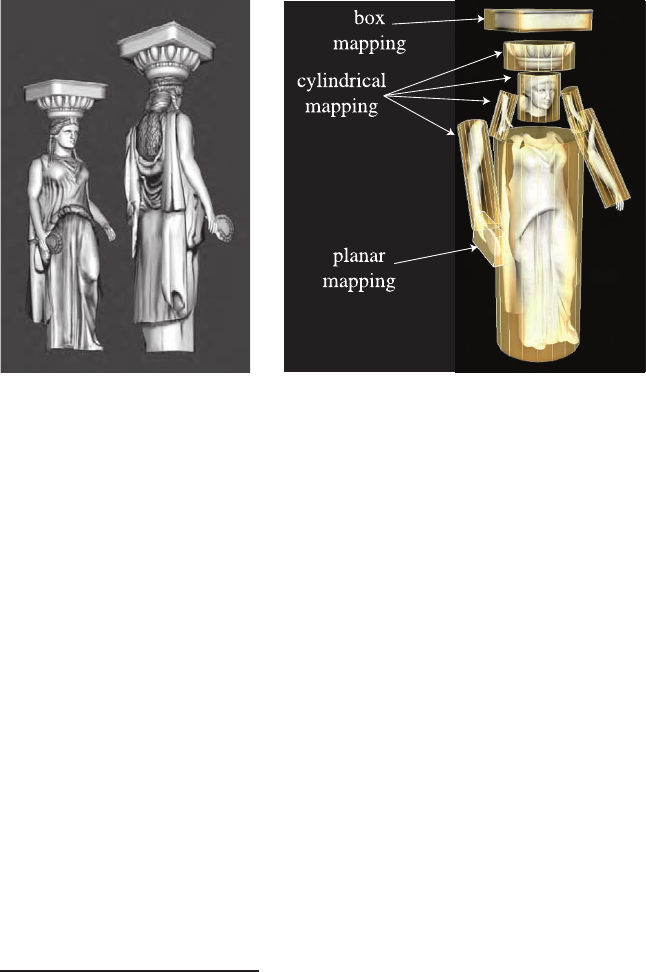
Figure 6.5. How various texture projections are used on a single model. (Images courtesy
of Tito Pag´an.)
In real-time work, projector functions are usually applied at the mod-
eling stage, and the results of the projection are stored at the vertices.
This is not always the case; sometimes it is advantageous to apply the
projection function in the vertex or pixel shader.
2
This enables various
effects, including animation (see Section 6.4). Some rendering methods,
such as environment mapping (see Section 8.4), have specialized projector
functions of their own that are evaluated per pixel.
The spherical projection casts points onto an imaginary sphere centered
around some point. This projection is the same as used in Blinn and
Newell’s environment mapping scheme (Section 8.4.1), so Equation 8.25 on
page 300 describes this function. This projection method suffers from the
same problems of vertex interpolation described in that section.
Cylindrical projection computes the u texturecoordinatethesameas
spherical projection, with the v texture coordinate computed as the dis-
tance along the cylinder’s axis. This projection is useful for objects that
have a natural axis, such as surfaces of revolution. Distortion occurs when
surfaces are near-perpendicular to the cylinder’s axis.
The planar projection is like an x-ray slide projector, projecting along
a direction and applying the texture to all surfaces. It uses orthographic
projection (Section 4.6.1). This function is commonly used to apply texture
2
This is also possible on fixed-function graphics hardware; for example, OpenGL’s
fixed-function glTexGen routine provides a few different projector functions, including
spherical and planar.

i
i
i
i
i
i
i
i
6.1. The Texturing Pipeline 153
Figure 6.6. A number of smaller textures for the statue model, saved in two larger
textures. The right figure shows how the polygonal mesh is unwrapped and displayed
on the texture to aid in its creation. (Images courtesy of Tito Pag´an.)
maps to characters, treating the model as if it were a paper doll by gluing
separate textures on to its front and rear.
As there is severe distortion for surfaces that are edge-on to the projec-
tion direction, the artist often must manually decompose the model into
near-planar pieces. There are also tools that help minimize distortion by
unwrapping the mesh, or creating a near-optimal set of planar projections,
or that otherwise aid this process. The goal is to have each polygon be
given a fairer share of a texture’s area, while also maintaining as much
mesh connectivity as possible. Connectivity is important in that sampling
artifacts can appear along the edges of textures, and each split vertex also
causes data to be duplicated in the mesh itself. A mesh with a good un-
wrapping also eases the artist’s work [723, 983]. Section 12.2.1 discusses
this problem’s effect on rendering. Figure 6.6 shows the workspace used
to create the statue in Figure 6.5. This unwrapping process is one facet
of a larger field of study, mesh parameterization. The interested reader is
referred to the SIGGRAPH course notes by Hormann et al. [567].
The parameter space is not always a two-dimensional plane; sometimes
it is a three-dimensional volume. In this case, the texture coordinates are
presented as a three-element vector, (u, v, w), with w being depth along
the projection direction. Other systems use up to four coordinates, often
designated (s, t, r, q) [969]; q is used as the fourth value in a homogeneous
coordinate (see Section A.4) and can be used for spotlighting effects [1146].
Another important type of parameter space is directional, where each point
in the parameter space represents a direction. One way to visualize such
i
i
i
i
i
i
i
i
154 6. Texturing
a space is as points on a unit sphere. The most common type of texture
using a directional parameterization is the cube map (see Section 6.2.4).
It is also worth noting that one-dimensional texture images and func-
tions have their uses. For example, these include contour lines [475, 969]
and coloration determined by altitude (e.g., the lowlands are green; the
mountain peaks are white). Lines can also be textured; one use of this is
to render rain as a set of long lines textured with a semitransparent im-
age. Such textures are also useful for simply converting from one value to
another.
Since multiple textures can be applied to a surface, multiple sets of tex-
ture coordinates may need to be defined. However the coordinate values
are applied, the idea is the same: These parameter values are interpolated
across the surface and used to retrieve texture values. Before being inter-
polated, however, these parameter values are transformed by corresponder
functions.
6.1.2 The Corresponder Function
Corresponder functions convert parameter-space coordinates to texture-
space locations. They provide flexibility in applying textures to surfaces.
One example of a corresponder function is to use the API to select a por-
tion of an existing texture for display; only this subimage will be used in
subsequent operations.
Another type of corresponder is a matrix transformation, which can be
applied in the vertex or pixel shader.
3
This enables to translating, rotating,
scaling, shearing, or projecting the texture on the surface.
4
Another class of corresponder functions controls the way an image is
applied. We know that an image will appear on the surface where (u, v)are
in the [0, 1) range. But what happens outside of this range? Corresponder
functions determine the behavior. In OpenGL, this type of corresponder
function is called the “wrapping mode”; in DirectX, it is called the “texture
addressing mode.” Common corresponder functions of this type are:
• wrap (DirectX), repeat (OpenGL), or tile—The image repeats itself
across the surface; algorithmically, the integer part of the parameter
value is dropped. This function is useful for having an image of a
material repeatedly cover a surface, and is often the default.
3
This is also possible on fixed-function hardware; the OpenGL fixed-function pipeline
supports the use of a 4 × 4matrix.
4
As discussed in Section 4.1.5, the order of transforms matters. Surprisingly, the
order of transforms for textures must be the reverse of the order one would expect. This
is because texture transforms actually affect the space that determines where the image
is seen. The image itself is not an object being transformed; the space defining the
image’s location is being changed.

i
i
i
i
i
i
i
i
6.1. The Texturing Pipeline 155
Figure 6.7. Image texture repeat, mirror, clamp, and border functions in action.
• mirror—The image repeats itself across the surface, but is mirrored
(flipped) on every other repetition. For example, the image appears
normally going from 0 to 1, then is reversed between 1 and 2, then
is normal between 2 and 3, then is reversed, etc. This provides some
continuity along the edges of the texture.
• clamp (DirectX) or clamp to edge (OpenGL)—Values outside the
range [0, 1) are clamped to this range. This results in the repetition
of the edges of the image texture. This function is useful for avoiding
accidentally taking samples from the opposite edge of a texture when
bilinear interpolation happens near a texture’s edge [969].
• border (DirectX) or clamp to border (OpenGL)—Parameter val-
ues outside [0, 1) are rendered with a separately defined border color.
This function can be good for rendering decals onto surfaces, for ex-
ample, as the edge of the texture will blend smoothly with the border
color.
See Figure 6.7. These corresponder functions can be assigned differently
for each texture axis, e.g., the texture could repeat along the u-axis and be
clampedonthev-axis.
Repeated tiling of a texture is an inexpensive way of adding more visual
detail to a scene. However, this technique often looks unconvincing after
about three repetitions of the texture, as the eye picks out the pattern.
Acommonsolutiontoavoidsuchperiodicity problems is to combine the
texture values with another, non-tiled, texture. This approach can be
considerably extended, as seen in the commercial terrain rendering system
described by Andersson [23]. In this system, multiple textures are combined
based on terrain type, altitude, slope, and other factors. Texture data is
also tied to where geometric models, such as bushes and rocks, are placed
within the scene.
Another option to avoid periodicity is to use shader programs to imple-
ment specialized corresponder functions that randomly recombine texture
patterns or tiles. Wang tiles are one example of this approach. A Wang
tile set is a small set of square tiles with matching edges. Tiles are selected
i
i
i
i
i
i
i
i
156 6. Texturing
randomly during the texturing process [1337]. Lefebvre and Neyret [748]
implement a similar type of corresponder function using dependent texture
reads and tables to avoid pattern repetition.
For real-time work, the last corresponder function applied is implicit,
and is derived from the image’s size. A texture is normally applied within
the range [0, 1) for u and v. As shown in the brick wall example, by mul-
tiplying parameter values in this range by the resolution of the image, one
may obtain the pixel location. The advantage of being able to specify
(u, v) values in a range of [0, 1) is that image textures with different reso-
lutions can be swapped in without having to change the values stored at
the vertices of the model.
6.1.3 Texture Values
After the corresponder functions are used to produce texture-space coor-
dinates, the coordinates are used to obtain texture values. For image tex-
tures, this is done by using the texture to retrieve texel information from
the image. This process is dealt with extensively in Section 6.2. Image
texturing constitutes the vast majority of texture use in real-time work,
but procedural functions are sometimes used. In the case of procedural
texturing, the process of obtaining a texture value from a texture-space
location does not involve a memory lookup, but rather the computation of
a function. Procedural texturing is further described in Section 6.3.
The most straightforward texture value is an RGB triplet that is used
to replace or modify the surface colors; similarly, a single grayscale value
could be returned. Another type of data to return is RGBα, as described
in Section 5.7. The α (alpha) value is normally the opacity of the color,
which determines the extent to which the color may affect the pixel. There
are many other types of data that can be stored in image textures, as will
be seen when bump-mapping is discussed in detail (Section 6.7).
The values returned from the texture are optionally transformed before
use. These transformations may be performed in the texturing hardware
or in the shader program. One common example is the remapping of data
from an unsigned range (0 to 1) to a signed range (−1to1). Anotheris
performing a comparison between the texture values and a reference value,
and returning a flag indicating the result of the comparison (often used in
shadow mapping—see Section 9.1.4).
6.2 Image Texturing
In image texturing, a two-dimensional image is effectively glued onto the
surface of a polygon. We have walked through the process of computing
..................Content has been hidden....................
You can't read the all page of ebook, please click here login for view all page.